EP1145860A1 - Cartouche retirable d'une tête d'impression à jet d'encre - Google Patents
Cartouche retirable d'une tête d'impression à jet d'encre Download PDFInfo
- Publication number
- EP1145860A1 EP1145860A1 EP01201199A EP01201199A EP1145860A1 EP 1145860 A1 EP1145860 A1 EP 1145860A1 EP 01201199 A EP01201199 A EP 01201199A EP 01201199 A EP01201199 A EP 01201199A EP 1145860 A1 EP1145860 A1 EP 1145860A1
- Authority
- EP
- European Patent Office
- Prior art keywords
- contacts
- ink cartridge
- mounting assembly
- cartridge
- inkjet printhead
- Prior art date
- Legal status (The legal status is an assumption and is not a legal conclusion. Google has not performed a legal analysis and makes no representation as to the accuracy of the status listed.)
- Withdrawn
Links
Images


Classifications
-
- B—PERFORMING OPERATIONS; TRANSPORTING
- B41—PRINTING; LINING MACHINES; TYPEWRITERS; STAMPS
- B41J—TYPEWRITERS; SELECTIVE PRINTING MECHANISMS, i.e. MECHANISMS PRINTING OTHERWISE THAN FROM A FORME; CORRECTION OF TYPOGRAPHICAL ERRORS
- B41J2/00—Typewriters or selective printing mechanisms characterised by the printing or marking process for which they are designed
- B41J2/005—Typewriters or selective printing mechanisms characterised by the printing or marking process for which they are designed characterised by bringing liquid or particles selectively into contact with a printing material
- B41J2/01—Ink jet
- B41J2/17—Ink jet characterised by ink handling
- B41J2/175—Ink supply systems ; Circuit parts therefor
- B41J2/17503—Ink cartridges
- B41J2/17526—Electrical contacts to the cartridge
- B41J2/1753—Details of contacts on the cartridge, e.g. protection of contacts
-
- B—PERFORMING OPERATIONS; TRANSPORTING
- B41—PRINTING; LINING MACHINES; TYPEWRITERS; STAMPS
- B41J—TYPEWRITERS; SELECTIVE PRINTING MECHANISMS, i.e. MECHANISMS PRINTING OTHERWISE THAN FROM A FORME; CORRECTION OF TYPOGRAPHICAL ERRORS
- B41J25/00—Actions or mechanisms not otherwise provided for
- B41J25/34—Bodily-changeable print heads or carriages
Definitions
- Ink jet printers have multiple electrical connection points and provide a means whereby the user can change the replaceable ink holding component in an out of a cartridge.
- the cartridge in tun provides a means to align with the electrical connections of the ink holding component and to provide contact pressures for electrical connectivity between the contact locations of the ink holding component and the "cartridge that supports and locates this ink holding component.”
- This invention generally relates to cartridge-type inkjet printheads of the type formed by the combination of an ink cartridge and a mounting assembly, and is particularly concerned with a mounting assembly which consistently and reliably applies a conductively engaging force between electrical contacts on the ink cartridge and control circuitry carried within the mounting assembly.
- Cartridge-type inkjet printheads are known in the prior art. Such printheads are formed by the combination of an ink cartridge and mounting assembly.
- the ink cartridge includes a row of inkjet nozzles on its bottom surface, and an array of electrical contact pads on this surface for conducting printer control signals to each of the various inkjet nozzles.
- the mounting assemblies for such printheads are provided with a control circuit having a plurality of contact buttons registrable with the contact pads of the cartridge which transmit printer control signals.
- Such mounting assemblies further include a mechanism for detachably securing the ink cartridge within the assembly in a position such that the electrical pads of the cartridge are in registry with the contact buttons of the printer control circuit.
- Such cartridge-type inkjet printheads are particularly adapted for use with document scanners which optically scan the printed information on documents, and convert the written information into digital form.
- the printheads are used to print an identifying number on each of the documents being scanned.
- the printhead number allows the user of the scanner to identify the image scanned in case a rescan is necessary due to poor or missing image information. It is important that the printhead be easily mountable on and removable from the scanner or other device as the ink cartridge must be periodically replaced due to exhaustion of its ink reservoir. For the same reason, the ink cartridge should be easily installable in and removable from the mounting assembly.
- the inkjets present on the bottom surface of the cartridge must align properly with the documents fed through a paper transport device in the scanner in order to insure that the index number printed on the documents is in a desired location.
- some sort of alignment mechanism must be present to insure registry between the contact pads and buttons.
- some sort of resilient means must be provided to insure that an electrically-conductive engagement is reliably created between the contact pads of the ink cartridge and the contact buttons of the control circuitry present within the mounting assembly.
- the necessary alignment between the contact pads of the ink cartridge and the contact buttons of the control circuitry is achieved through a plurality of assembled parts. Additionally, the pressure to form the necessary electrical engagement between these contacts is generated by a single compliant, elastomeric pad that has a series of projections or springs that press the contact pads and buttons together.
- a printhead cartridge having a mounting assembly formed from a small number of easily assembled parts to reduce the problems associated with the cumulative tolerances and the expenses associated with multi-part construction.
- a mounting assembly should have a plurality of mechanically independent spring members for generating the necessary contact pressure between the pads of the ink cartridge and the buttons of the control circuitry to insure that the necessary contact pressure is consistently and reliably generated, despite any misalignments and non-uniformities and planarities caused by cumulative tolerances and dried ink deposits.
- the invention is an inkjet printhead that eliminates or ameliorates all of the aforementioned problems associated with the prior art.
- the inkjet printhead comprises an ink cartridge having a plurality of inkjet nozzles, and a plurality of electrical contacts for conducting control signals to the nozzles, and a mounting assembly having a retainer for releasably securing the ink cartridge, and a plurality of mechanically independent spring members for pressing electrical contacts of a printer control circuit into conductive engagement with the contacts of the ink cartridge.
- Each of the independent spring members is preferably independently cantilevered from a wall of the mounting assembly.
- Each spring member may have a proximal end that is integrally connected to the wall of the mounting assembly, and a distal end that includes a projecting nub for engaging one of the printer control circuit contacts.
- the wall of the mounting assembly is preferably formed from an injection moldable plastic material, and the integral connection and formation of the cantilevered spring members with the wall advantageously provides a design that is easily accurately manufactured, and which provides uniform engagement pressures between the contacts.
- the retainer of the mounting assembly includes at least one locking member for engaging the contacts of the ink cartridge against the contacts of the circuit when the retainer secures the ink cartridge in the mounting assembly.
- the retainer may include a pair of leg members pivotally mounted in side walls of the mounting assembly, and locking lugs at each end of each leg for applying an engagement force against lock flanges provided on the ink cartridge.
- the mounting assembly and the cartridge include interfitting members such as pegs and holes for creating the desired alignment.
- An alignment means for the control circuit captured within the mounting assembly is also provided which may take the form of registry holes in the control circuit through which alignment pegs of a circuit retainer are inserted during the construction of the mounting assembly.
- the mounting assembly may further include a mechanism for detachably connecting the printhead to a printer.
- the mounting assembly may take the form of resilient fingers which snap-fit into opposing slots provided in a printer well of the printer, in combination with alignment ribs which are insertable into a selected one of a plurality of slots in the printer well. Such a structure allows the position of the printhead on the printer to be adjusted so that the position of the printed index number or other image may be adjusted on the paper fed through the printer.
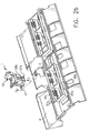
- the printhead assembly 1 of the invention is particularly adapted for use in a scanner 2 that scans documents and converts the printed information thereon into digitized form.
- the printer assembly 1 prints an identifying number on documents fed through the scanner 2, which number is also incorporated into the digitized, electronic document created by the CCD module of the scanner 2.
- the printhead assembly 1 is detachably mounted to a printer well 3 that is likewise detachably mounted on the exterior surface of a semi-cylindrical paper guide 4.
- the scanner 2 includes a plurality of rollers 6 for conveying documents around the semi-circular path defined by the paper guide 4.
- a paper sensor 8 is provided on the exterior of the guide 4 for actuating the printer assembly 1. Together, the printhead assembly 1, we113, paper guide 4, rollers 6, and paper sensor 8 form a printer 9 for the scanner 2.
- a camera assembly 10 is disposed within the semi-cylindrical paper guide 4 for optically reading the printed information on the documents fed through the paper guide 4.
- the camera assembly 10 includes a housing 12 and the previously mentioned CCD module 14.
- a plurality of mirrors 16 allows the CCD module to detect light reflected from documents circulating around the paper guide 4 through a slide 18 provided in an inner guide member 20.
- the various components of the scanner 2 are conventional, and form no part of the instant invention.
- the printhead assembly 1 is formed from the combination of a mounting assembly 25, and an ink cartridge 27.
- the principal purposes of the mounting assembly 25 are (1) to establish secure electrical connections between the printer circuit board in the ink cartridge 27 and the control circuitry of the printer; (2) to provide a means whereby the printhead assembly 1 may be easily installed and removed from the printer well 3 via a snap-fit arrangement, and (3) to provide a means for the ink cartridge to be easily secured into and removed from the mounting assembly for replacement or maintenance.
- the mounting assembly 25 includes a bottom wall 30 over which the ink cartridge 27 is mountable.
- Bottom wall 30 includes a plurality of cantilevered spring members 31. As is best seen in Figure 5, each of these cantilevered spring members 31 terminates in a projecting nub 33.
- the integral, cantilevered structure of the spring members 31 in combination with the projecting nubs 33 form independent, spring-loaded members which are responsible for securing electrical connection between contact pads of ink cartridge 25 and the contact buttons of a printer control circuit.
- Bottom wall 30 also includes inner alignment holes 34a,b and outer alignment holes 35a,b which cooperate with similar alignment holes in the circuit assembly 60 of the printer to align button contacts present in this circuit with the aforementioned, spring-loaded nubs 33.
- the mounting assembly 25 further includes a pair of opposing side walls 36a,b. Each of these side walls includes a resilient retaining fingers 37a,b. These fingers, 37a,b, are insertable into complementary slots 37c,d present in the printer well 3 in order to detachably connect the printer assembly 1 via a snap-fit mechanism (as is indicated in Figure 2B). Each of the side walls 36a,b further includes an alignment rib 38a,b which is insertable into a selected one of several vertically-oriented slots 38c,d in the printer well 3. The various pairs of vertically-oriented slots 38c,d allow the position of the printhead 1 to be adjusted relative to the documents fed through the paper guide 4.
- Mounting assembly 25 also has a back wall 40 integrally connected to the bottom wall 30 and side walls 36a,b.
- Back wall 40 includes, near its upper end, a circuit admission slot 42 for receiving the flexible circuit assembly of the printer 1.
- a pair of retaining clips 44a,b project from the back side of the wall 40 for securing the connector terminal of the circuit assembly.
- the mounting assembly 25 has a cartridge retainer 46 formed from a handle 48 and two opposing legs 50a,b.
- Stub axles 52a,b project from each of the legs 50a,b and are snap-fittable into the axle holes 39a,b due to the resiliency of the plastic or other material forming the retainer.
- Each of the legs 50a,b has a longitudinally-shaped locking recess 53a,b at its lower end. These recesses cooperate with the inner side of each of the previously discussed retaining fingers 37a,b present in side walls 36a,b to help secure the cartridge retainer 36 in a cartridge-retaining position when the retainer 46 is pivoted into the position illustrated in Figures 2B and 3.
- a pair of locking cams 54a,b are defined by the flat bottom surfaces of each of the legs 50a,b of the retainer 46. Finally, flat portions projecting from the front of the legs 50a,b form stop portions 56a,b which abut the back wall 40 of the mounting assembly 25 when the retainer 46 is pivoted into a cartridge-retaining position.
- the printer assembly 1 further has a flexible circuit assembly 60.
- the circuit assembly 60 includes a foot portion 62 having an array of contact buttons 64. Each of these contact buttons 64 is registrable with a contact pad located on the bottom wall of the ink cartridge 27. Disposed outside of the contact buttons 64 are two pairs of alignment holes 66a,b.
- the circuit assembly 60 further includes, on its opposite end, a connector terminal 68 which snap-fits into position behind the upper portion of back wall 40 of the mounting assembly 25 via retaining clips 44a,b.
- a circuit retainer 70 is provided for securing the central portion of the flexible circuit assembly 60 to the back wall 40 of the mounting assembly 25.
- the circuit retainer 70 has a pair of retaining feet 72a,b, as shown. These feet 72a,b include alignment pegs 74a,b which are registrable with the alignment holes 66a,b present in the foot portion 62 of the circuit assembly 60.
- the circuit retainer 70 also has a retaining wall 76 integrally connected to the retaining feet 72 for capturing and pressing the central portion of the circuit assembly 60 against the back wall 40 of the mounting assembly 25.
- the retainer 70 is provided with a pair of opposing, resilient fingers 78a,b which snap-fit into opposing sides of the circuit admission slot 42 of back wall 40 in order to secure the retainer 70 onto the mounting assembly 25.
- the ink cartridge 27 of the printer assembly 1 includes an ink reservoir 80 for storing a supply of ink.
- a handle 82 extends from the side of the ink reservoir 80 to facilitate the insertion and removal of the cartridge 27 from the mounting assembly 25.
- the base 84 of the ink cartridge 27 is provided with a pair of alignment pegs 86a,b which are registrable in and insertable into outer alignment holes 35a,b located on the bottom wall 30 of the mounting assembly 25.
- Centrally disposed on the bottom of the base 84 is a circuit board 88 having a plurality of contact pads 90. Each of the contact pads 90 controls one of the plurality of printing orifices 92 present on the printer face 94.
- the base 84 of the ink cartridge 27 includes a pair of opposing retaining flanges for a purpose which will become evident shortly.
- the mounting assembly 25 of the printhead 1 is first mounted by extending the foot portion 62 of the flexible circuit assembly 60 through the back of the admission slot 42 of the back wall 40.
- the alignment holes 66 of the foot portion 52 are next placed into registry with the inner alignment holes 34a,b present on the bottom wall 30, as is partly shown in Figure 5.
- the alignment pegs 74a,b of the circuit retainer 70 are next inserted through the registered alignment holes 66a,b and 34a,b and the resilient fingers 78a,b are snapped into the ends of the slot 42 of back wall 40.
- Terminal connector 68 is then attached to the upper rear portion of the back wall 40 via retaining clips 44a,b.
- the handle 48 of the cartridge retainer 46 is pivoted against the back wall 40 in the direction indicated by the arrow in Figure 3.
- the ink cartridge 27 is then slid over the bottom wall 30 of the mounting assembly 25 until the alignment pegs 86a,b are aligned and inserted into the outer alignment holes 35a,b of the bottom wall 30.
- the handle 48 of the cartridge retainer 46 is then pivoted away from the back wall 40 in the direction opposite from that indicated by the arrow in Figure 3.
- the locking cams 54a,b located on the bottom of the cartridge retainer 46 forcefully engage the retaining flanges 96a,b on the base 84 of the ink cartridge 27 downwardly to press the contact pads 90 of the cartridge 27 against contact buttons 64.
- the legs 50a,b of the cartridge retainer 46 are snap-fitted into this cartridge locking position by the action of the resilient retaining fingers 37a,b snapping into the locking recesses 53a,b on the bottom portion of the legs of cartridge retainer 46.
- the registration and insertion of the alignment pegs 86a,b of the ink cartridge 27 with the outer alignment holes 35a,b of bottom wall 30 insures the registration of the contact buttons 64 of the flexible circuit assembly 60 with the contact pads 90 of the ink cartridge 27.
Landscapes
- Ink Jet (AREA)
Applications Claiming Priority (2)
| Application Number | Priority Date | Filing Date | Title |
|---|---|---|---|
| US549123 | 1983-11-04 | ||
| US54912300A | 2000-04-13 | 2000-04-13 |
Publications (1)
| Publication Number | Publication Date |
|---|---|
| EP1145860A1 true EP1145860A1 (fr) | 2001-10-17 |
Family
ID=24191762
Family Applications (1)
| Application Number | Title | Priority Date | Filing Date |
|---|---|---|---|
| EP01201199A Withdrawn EP1145860A1 (fr) | 2000-04-13 | 2001-04-02 | Cartouche retirable d'une tête d'impression à jet d'encre |
Country Status (2)
| Country | Link |
|---|---|
| EP (1) | EP1145860A1 (fr) |
| JP (1) | JP2001322259A (fr) |
Cited By (3)
| Publication number | Priority date | Publication date | Assignee | Title |
|---|---|---|---|---|
| EP1418054A1 (fr) | 2002-11-07 | 2004-05-12 | Océ-Technologies B.V. | Ensemble d'un chariot d'impression et méthode pour le montage d'un support de tête d'impression sur l'ensemble |
| JP2004155195A (ja) * | 2002-11-07 | 2004-06-03 | Oce Technol Bv | プリントキャリッジアセンブリ及びそのアセンブリにプリンタヘッドホルダーを設置するための方法 |
| WO2009092317A1 (fr) * | 2008-01-15 | 2009-07-30 | Zhuhai Nine Star Electronic Science And Technology Co., Ltd. | Protection pour puce de tête d'impression et cartouche utilisée avec cette protection |
Citations (6)
| Publication number | Priority date | Publication date | Assignee | Title |
|---|---|---|---|---|
| EP0376719A2 (fr) * | 1988-12-29 | 1990-07-04 | Canon Kabushiki Kaisha | Tête d'enregistrement à jet d'encre et appareil d'enregistrement à jet d'encre |
| EP0553561A2 (fr) * | 1991-12-25 | 1993-08-04 | Canon Kabushiki Kaisha | Dispositif d'enregistrement à jet d'encre |
| EP0603901A2 (fr) * | 1992-12-25 | 1994-06-29 | Canon Kabushiki Kaisha | Unité pour produire un jet d'encre détachable et appareil d'enregistrement par jet d'encre |
| EP0622233A2 (fr) * | 1993-04-30 | 1994-11-02 | Hewlett-Packard Company | Système d'interconnexion électrique pour une imprimante |
| EP0696082A1 (fr) * | 1994-08-04 | 1996-02-07 | Canon Kabushiki Kaisha | Appareil de traitement d'informations comportant un membre élastique utilisé pour le contact électrique de fonction |
| EP0847866A2 (fr) * | 1994-11-02 | 1998-06-17 | Seiko Epson Corporation | Réservoir d'alimentation en encre pour une unité d'enregistrement à jet d'encre |
-
2001
- 2001-04-02 EP EP01201199A patent/EP1145860A1/fr not_active Withdrawn
- 2001-04-11 JP JP2001112635A patent/JP2001322259A/ja active Pending
Patent Citations (6)
| Publication number | Priority date | Publication date | Assignee | Title |
|---|---|---|---|---|
| EP0376719A2 (fr) * | 1988-12-29 | 1990-07-04 | Canon Kabushiki Kaisha | Tête d'enregistrement à jet d'encre et appareil d'enregistrement à jet d'encre |
| EP0553561A2 (fr) * | 1991-12-25 | 1993-08-04 | Canon Kabushiki Kaisha | Dispositif d'enregistrement à jet d'encre |
| EP0603901A2 (fr) * | 1992-12-25 | 1994-06-29 | Canon Kabushiki Kaisha | Unité pour produire un jet d'encre détachable et appareil d'enregistrement par jet d'encre |
| EP0622233A2 (fr) * | 1993-04-30 | 1994-11-02 | Hewlett-Packard Company | Système d'interconnexion électrique pour une imprimante |
| EP0696082A1 (fr) * | 1994-08-04 | 1996-02-07 | Canon Kabushiki Kaisha | Appareil de traitement d'informations comportant un membre élastique utilisé pour le contact électrique de fonction |
| EP0847866A2 (fr) * | 1994-11-02 | 1998-06-17 | Seiko Epson Corporation | Réservoir d'alimentation en encre pour une unité d'enregistrement à jet d'encre |
Cited By (5)
| Publication number | Priority date | Publication date | Assignee | Title |
|---|---|---|---|---|
| EP1418054A1 (fr) | 2002-11-07 | 2004-05-12 | Océ-Technologies B.V. | Ensemble d'un chariot d'impression et méthode pour le montage d'un support de tête d'impression sur l'ensemble |
| JP2004155195A (ja) * | 2002-11-07 | 2004-06-03 | Oce Technol Bv | プリントキャリッジアセンブリ及びそのアセンブリにプリンタヘッドホルダーを設置するための方法 |
| US7090329B2 (en) | 2002-11-07 | 2006-08-15 | Oce-Technologies B.V. | Print carriage assembly and method for mounting a print head holder thereon |
| WO2009092317A1 (fr) * | 2008-01-15 | 2009-07-30 | Zhuhai Nine Star Electronic Science And Technology Co., Ltd. | Protection pour puce de tête d'impression et cartouche utilisée avec cette protection |
| US8342665B2 (en) | 2008-01-15 | 2013-01-01 | Zhuhai Ninestar Management Co., Ltd. | Protector for print head chip and ink cartridge used by the same |
Also Published As
| Publication number | Publication date |
|---|---|
| JP2001322259A (ja) | 2001-11-20 |
Similar Documents
| Publication | Publication Date | Title |
|---|---|---|
| KR100518197B1 (ko) | 잉크 카트리지 및 기록 장치 | |
| US5861897A (en) | Inkjet recording apparatus with a memory device disposed substantially within boundaries if a recording head unit | |
| EP0993954A3 (fr) | Système d'impression par jet d'encre utilisant un assemblage modulaire de cartouche d'encre | |
| EP0622233A2 (fr) | Système d'interconnexion électrique pour une imprimante | |
| TWI513599B (zh) | 印章及相關聯印台 | |
| EP0992348A3 (fr) | Cartouche d'impression modulaire pour usage dans des systèmes d'impression à jet d'encre | |
| EP1145860A1 (fr) | Cartouche retirable d'une tête d'impression à jet d'encre | |
| US20090195364A1 (en) | Rfid linking device-based switchable sensor, component with switchable sensor, and system for detecting component unseated | |
| RU2638627C2 (ru) | Блок контактных выводов, блок подачи чернил и адаптер | |
| EP1535744A1 (fr) | Tête jet d'encre, et réservoir d'encre | |
| EP1078769B1 (fr) | Elément d'impression et méthode pour assembler une tête d'impression | |
| ES2226044T3 (es) | Contenedor de almacenamiento para cartuchos para chorros de tinta que tiene medios de limpieza y metodo para el almacenamiento de cartuchos para chorros de tinta. | |
| CN110341314B (zh) | 加盖机构和喷墨打印机 | |
| WO2003016066A1 (fr) | Module de connexion | |
| JP2002234191A (ja) | インクジェットプリンタの電気的な接点装置 | |
| CN214122699U (zh) | 处理盒 | |
| EP0861725A3 (fr) | Tête d'impression à jet d'encre | |
| JPH08108546A (ja) | インクジェット記録装置 | |
| US20070224874A1 (en) | Connector and recording apparatus having the same | |
| KR100492088B1 (ko) | 선접촉구조를 갖는 인쇄장치 및 전자기기 | |
| KR0164537B1 (ko) | 잉크젯 프린트기기에 있어서 헤드의 파워 연결 단자부 청소장치 | |
| JP5716387B2 (ja) | コネクターユニットおよびこれを備えた記録装置 | |
| JP2007276495A (ja) | 記録装置 | |
| EP1286431B1 (fr) | Connecteur électrique à positionnement prédéterminé | |
| CN111497453A (zh) | Ic芯片座 |
Legal Events
| Date | Code | Title | Description |
|---|---|---|---|
| PUAI | Public reference made under article 153(3) epc to a published international application that has entered the european phase |
Free format text: ORIGINAL CODE: 0009012 |
|
| AK | Designated contracting states |
Kind code of ref document: A1 Designated state(s): AT BE CH CY DE DK ES FI FR GB GR IE IT LI LU MC NL PT SE TR Kind code of ref document: A1 Designated state(s): DE FR GB |
|
| AX | Request for extension of the european patent |
Free format text: AL;LT;LV;MK;RO;SI |
|
| 17P | Request for examination filed |
Effective date: 20020318 |
|
| AKX | Designation fees paid |
Free format text: DE FR GB |
|
| 17Q | First examination report despatched |
Effective date: 20050503 |
|
| STAA | Information on the status of an ep patent application or granted ep patent |
Free format text: STATUS: THE APPLICATION IS DEEMED TO BE WITHDRAWN |
|
| 18D | Application deemed to be withdrawn |
Effective date: 20050914 |