EP1145908B1 - Plateau de chargement - Google Patents
Plateau de chargement Download PDFInfo
- Publication number
- EP1145908B1 EP1145908B1 EP01890112A EP01890112A EP1145908B1 EP 1145908 B1 EP1145908 B1 EP 1145908B1 EP 01890112 A EP01890112 A EP 01890112A EP 01890112 A EP01890112 A EP 01890112A EP 1145908 B1 EP1145908 B1 EP 1145908B1
- Authority
- EP
- European Patent Office
- Prior art keywords
- loading floor
- floor according
- upper frame
- lower frame
- loading
- Prior art date
- Legal status (The legal status is an assumption and is not a legal conclusion. Google has not performed a legal analysis and makes no representation as to the accuracy of the status listed.)
- Expired - Lifetime
Links
- 239000002184 metal Substances 0.000 claims description 3
- 230000037431 insertion Effects 0.000 claims 1
- 238000003780 insertion Methods 0.000 claims 1
- 239000011324 bead Substances 0.000 description 2
- 150000001875 compounds Chemical class 0.000 description 1
- 230000000694 effects Effects 0.000 description 1
- 230000002349 favourable effect Effects 0.000 description 1
- 230000012447 hatching Effects 0.000 description 1
- 239000002650 laminated plastic Substances 0.000 description 1
- 238000004519 manufacturing process Methods 0.000 description 1
- 239000011120 plywood Substances 0.000 description 1
Images


Classifications
-
- B—PERFORMING OPERATIONS; TRANSPORTING
- B60—VEHICLES IN GENERAL
- B60R—VEHICLES, VEHICLE FITTINGS, OR VEHICLE PARTS, NOT OTHERWISE PROVIDED FOR
- B60R5/00—Compartments within vehicle body primarily intended or sufficiently spacious for trunks, suit-cases, or the like
- B60R5/04—Compartments within vehicle body primarily intended or sufficiently spacious for trunks, suit-cases, or the like arranged at rear of vehicle
Definitions
- the invention relates to a loading floor for the loading space of a motor vehicle, which has a loading space covering plate and against the Cargo space at least in part and at least substantially parallel to Vehicle floor is retractable and retractable.
- the loading floor is just one plate formed, which covers the bottom of the rear-side cargo space of the motor vehicle. Access to the space below the loading floor, where usually still Storage space for tools or for the spare wheel is provided, can be made possible by folding up the loading floor.
- the loading of such Cargo holds is cumbersome and cumbersome when carrying heavy cargoes over the often relatively high sill in the rear of the vehicle in the hold have to be hoisted. Also, the stowage bulky and bulky Goods are often difficult.
- a loading floor for the loading space of a motor vehicle which has a pallet, Manually from a transport position where the pallet is completely in Trunk is received, is movable in a loading and unloading position, in the the pallet protrudes partially from the trunk.
- the loading floor has one Base for supporting on the floor of the trunk and a pallet having upper part. Between the lower part and the upper part is a Gear or guide arrangement effectively, with which the pallet at least can be raised at its one end.
- the at least one Lever assembly having gear or guide means causes at the same time a swinging and extending the pallet.
- the plate on a first upper frame is arranged, which relative to a second the lower frame is slidably mounted, the two frames in unshifted position in the vertical direction can be lifted together and are lowered, wherein in the jointly raised position of the upper frame opposite the lower frame in horizontal direction for extension and retraction the upper frame is displaceable, and wherein all movements of the Frame via electric motors are feasible.
- the loading floor with a be designed much higher load capacity and rigidity than in the known solution. Through both vertically and horizontally possible movements little space is needed and it is thus also the Cargo volume in the imported state not reduced.
- An invention executed loading floor can also in a visually perfect manner in Vehicle to be integrated. The automatic operation sets a high Ease of use safe.
- the lower frame in a simple manner by means of vehicle-supported supported lifting devices can be raised and lowered (Claim 2).
- the lifting devices are worm gear, the are connected to propeller shafts, which are driven by one of the electric motors (Claim 3).
- the operative connection of the thruster to the upper frame can be simple Way via a connected to the upper frame part done with which which is connected to the feed screw engaged spindle nut (Claims 6 and 7).
- connection of the shafts to the lateral frame parts of the upper frame can be easily done via shaft supports acting on the shafts and the Upper frame are attached, carried out (claim 11).
- a functionally reliable storage of the feed screw is characterized, for example performed that at the bottom of the lower frame in at least a slide bearing holder and is mounted in at least one spindle bearing (claim 12).
- a functionally reliable storage of the feed screw is characterized, for example performed that at the bottom of the lower frame in at least a slide bearing holder and is mounted in at least one spindle bearing (claim 12).
- the lower frame can be lightweight and with sufficient stability be executed by composing in particular U-shaped profiles is (claim 14).
- the upper frame is made for reasons of resilience and stability in particular a sheet metal stamping or the like, which provided centrally with an opening may be (claim 15).
- a sheet metal stamping or the like which provided centrally with an opening may be (claim 15).
- About the central breakthrough can provide access to the objects accommodated in or below the loading floor, for example the spare wheel.
- the plate at the front Edge region of the upper frame is pivotally mounted (claim 16).
- cargo floor is used in the context of the present invention Furthermore, the entire, the rear cargo space of the vehicle covering Device understood.
- the visible in the cargo space Part of the loading floor formed by a plate 7, for example, a laminated plastic or plywood panel may be.
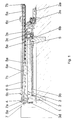
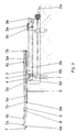
- Fig. 2 shows close side of the plate 7, the two cargo space panels 11 at.
- the loading edge 12 of the rear portion of the motor vehicle see Fig. 1
- the particular rectangular plate 7 is on an upper Frame 6 stored, which is here a sheet metal stamping and centered with a large, Not shown here breakthrough may be provided so that in the field of Loading floor below the plate 7 accommodated items, for example the spare wheel, are accessible.
- the adapted to the shape of the plate 7 upper Frame 6 is designed at least substantially rectangular and is at his two upper longitudinal edges provided with mitstanzten retaining tabs 6 c, the Plate 7 protrude laterally and are provided to Festhaltegurte for cargo Fasten.
- the plate 7 is at its front edge region by means of hinges 7b pivotally mounted on the front edge of the frame 6.
- the plate 7 are fixed on its underside plate holder 7a, in particular from Fig. 4 can be seen and in each case via a movably mounted latch have, by means of which the plate 7 releasably engaged on the upper frame 6 can be.
- a release of the plate holder 7 a will take place when the plate 7, For example, to gain access to the spare wheel, to be folded up.
- Fig. 1 shows one each of the front and one of the rear Helical screw 1, from Fig. 2, the two are arranged rearwardly Helical screw 1 can be seen.
- Flexible cardan shafts 2 connect to each Side a rear with a front worm gear 1 and this with an electric motor 2 a, which is for example a 12 V motor and also at the Vehicle body, here between the two front worm gearboxes 1, is attached.
- the flexible propeller shafts 2 are about the motor 2a for Actuation of the worm gear 1 driven.
- the worm gear 1 are for vertical moving up and down a lower frame 3 is provided, which can be moved in the vertical direction Parts of the screw jack 1 is mounted.
- the lower frame 3 is in particular a rectangular frame composed of U-shaped profiles can.
- On top of the lower frame 3 are at the front areas the two lateral frame parts depending on a groove-like receiving ramps 3a, in particular made of plastic, mounted where in retracted State, at rest, each a wave 5, which will be discussed later is, retracted and finally tostüzt is.
- the upper frame 6 is in common with the lower frame 3 in vertical Direction movable and compared to the lower frame 3 in horizontal Direction to the rear and thus out of the rear of the vehicle out movable.
- the feed screw 3b which upon actuation of the loading floor is stationary relative to the lower frame 3, is in the front end in a likewise attached to the lower frame 3 slide bearing holder 3c and with her rear end region in a spindle bearing attached to the lower frame 3 3d stored.
- the front end of the feed screw 3b is at another Electric motor 3e, which is also a 12 V engine, coupled, which at the illustrated embodiment is attached to the lower frame 3.
- the engine is 3e for a drive of the feed screw 3b and thus for an extension and retraction movement responsible for the loading floor.
- each linear housing 4 On the top of the running in the vehicle longitudinal direction side frame parts of the lower frame 3 are also two linear housing 4 at a distance attached to each other, in each of which a number of linear ball bearings 4a are included. On each side is in the linear ball bearings 4a each linear housing 4 a shaft 5 slidably mounted.
- the two linear housings 4 on each frame side are also in the transverse direction each offset from each other, so that each one of the waves 5 in one of Linear housing 4 is mounted.
- the two pairs of shafts 5 are in particular the same length, but shorter than the length of the plate 7, wherein the one Wave 5 to the rear and the other wave 5 to the front end of the Plate 7 runs.
- a shaft support 5a is mounted at each of the end portions of each shaft 5.
- the upper frame 6 is fixed.
- the operation of the loading floor according to the invention for extending and retracting is as follows.
- the tailgate open which is not shown in the drawing figures is an inbuilt on the vehicle in an easily accessible location Switch or the like can be actuated.
- a not subject of the present Invention forming electronics now causes a corresponding driving the two electric motors 2a, 3e.
- About the electric motor 2a are the first Pivot shafts 2 of the worm gear 1 operated, so that the lower frame. 3 together with all other components arranged on it in the vertical direction is lifted.
- the lifting movement is stopped automatically in particular, as soon as the extendable parts of the loading floor, these are in particular the plate. 7 with the upper frame 6 and with the plate 7 via the shaft supports 5a connected shafts 5, over the loading edge 12 are movable.
- a stop mechanism for example on the plate 7 and the upper frame 6, provide, so that the plate 7 in her pivoted up position, for example, to remove the spare wheel, solvable can be fixed.
- the invention is not limited to the illustrated embodiment. So in particular, it is possible to use the two electric motors elsewhere presented to accommodate. It is also possible, instead of four Schneckenhubgetrieben provide three, of which two in the rear area at the Vehicle body and one is attached approximately in the middle in the front area. At The position of the worm gear and feed screw may be different and thrusters are used. Basically, others can Components of the loading floor are replaced by the same or similar effect.
Landscapes
- Engineering & Computer Science (AREA)
- Mechanical Engineering (AREA)
- Vehicle Step Arrangements And Article Storage (AREA)
- Buildings Adapted To Withstand Abnormal External Influences (AREA)
- Body Structure For Vehicles (AREA)
- Fluid-Damping Devices (AREA)
- Steam Or Hot-Water Central Heating Systems (AREA)
- Footwear And Its Accessory, Manufacturing Method And Apparatuses (AREA)
- Vehicle Body Suspensions (AREA)
Claims (17)
- Plancher de chargement pour le compartiment de charge d'un véhicule automobile, qui présente une plaque recouvrant le compartiment de charge et peut être sorti et rentré par rapport au compartiment de charge du moins partiellement et du moins sensiblement parallèlement au plancher du véhicule,
caractérisé en ce que
la plaque (7) est disposée sur un premier châssis supérieur (6) qui s'appuie de manière mobile par rapport à un deuxième châssis inférieur (3), les deux châssis (3, 6) pouvant, en position non décalée, être montés et descendus ensemble dans le sens vertical, tandis que, dans la position où ils sont montés ensemble, le châssis supérieur (6) est déplaçable par rapport au châssis inférieur (3) dans le sens horizontal pour rentrer et sortir le châssis supérieur (5) et que tous les mouvements des châssis (3, 6) peuvent être exécutés à l'aide de moteurs électriques (2a, 3a). - Plancher de chargement selon la revendication 1, caractérisé en ce que le châssis inférieur (3) peut être monté et descendu au moyen de dispositifs de levage (1) s'appuyant fixement sur le véhicule.
- Plancher de chargement selon la revendication 2, caractérisé en ce que les dispositifs de levage sont des engrenages à vis sans fin (1) qui sont reliés à des arbres articulés (2) qui peuvent être entraínés par un des moteurs électriques (2a).
- Plancher de chargement selon une des revendications 1 à 3, caractérisé en ce que le châssis supérieur (6) est déplaçable par rapport au châssis inférieur (3) à l'aide d'un dispositif de poussée.
- Plancher de chargement selon la revendication 4, caractérisé en ce que le dispositif de poussée présente au moins un mandrin d'avance (3b) s'appuyant sur le châssis inférieur (3).
- Plancher de chargement selon la revendication 4 ou 5, caractérisé en ce que le dispositif de poussée est en liaison fonctionnelle avec une pièce reliée au châssis supérieur (6).
- Plancher de chargement selon la revendication 6, caractérisé en ce que la pièce fixée au châssis supérieur (6) est une pièce de connexion (6b) comportant un écrou de broche.
- Plancher de chargement selon une des revendications 4 à 7, caractérisé en ce que le dispositif de poussée peut être entraíné par un des moteurs électriques (3a).
- Plancher de chargement selon une des revendications 1 à 8, caractérisé en ce qu'il est prévu, sur le châssis inférieur (3), des paliers à glissement pour des arbres (5) ou similaires, qui sont reliés au châssis supérieur (6).
- Plancher de chargement selon la revendication 9, caractérisé en ce que les paliers à glissement sont des paliers à billes linéaires (4a) qui sont encastrés dans des boítiers linéaires (4) fixés sur le châssis supérieur (6).
- Plancher de chargement selon une des revendications 1 à 10, caractérisé en ce que, sur la face inférieure des pièces de châssis latérales du châssis supérieur (6), sont fixés à chaque fois deux arbres (5), notamment à l'aide de supports d'arbres (5a) ou similaires.
- Plancher de chargement selon une des revendications 5 à 11, caractérisé en ce que le mandrin d'avance (3b) s'appuie sur la face inférieure du châssis inférieur (3) dans au moins un support de palier à glissement (3c) et au moins un palier de mandrin (3d).
- Plancher de chargement selon une des revendications 1 à 12, caractérisé en ce qu'il est prévu au moins trois engrenages à vis sans fin (1) reliés au châssis inférieur (3).
- Plancher de chargement selon une des revendications 1 à 13, caractérisé en ce que le châssis inférieur (3) est composé de profilés notamment en forme de U.
- Plancher de chargement selon une des revendications 1 à 14, caractérisé en ce que le châssis supérieur (6) est une pièce de tôle estampée ou similaire qui est pourvue de préférence d'une percée.
- Plancher de chargement selon une des revendications 1 à 15, caractérisé en ce que la plaque (7) s'appuie de manière pivotable sur la zone périphérique avant du châssis supérieur (6).
- Plancher de chargement selon une des revendications 1 à 16, caractérisé en ce que la plaque (7) et le châssis supérieur (6) sont pourvus à des points concordants de points de cassure théorique s'étendant dans le sens transversal du véhicule.
Priority Applications (1)
| Application Number | Priority Date | Filing Date | Title |
|---|---|---|---|
| AT01890112T ATE300447T1 (de) | 2000-04-11 | 2001-04-11 | Ladeboden |
Applications Claiming Priority (2)
| Application Number | Priority Date | Filing Date | Title |
|---|---|---|---|
| AT6182000 | 2000-04-11 | ||
| AT0061800A AT409620B (de) | 2000-04-11 | 2000-04-11 | Ladeboden |
Publications (3)
| Publication Number | Publication Date |
|---|---|
| EP1145908A2 EP1145908A2 (fr) | 2001-10-17 |
| EP1145908A3 EP1145908A3 (fr) | 2003-08-27 |
| EP1145908B1 true EP1145908B1 (fr) | 2005-07-27 |
Family
ID=3677582
Family Applications (1)
| Application Number | Title | Priority Date | Filing Date |
|---|---|---|---|
| EP01890112A Expired - Lifetime EP1145908B1 (fr) | 2000-04-11 | 2001-04-11 | Plateau de chargement |
Country Status (3)
| Country | Link |
|---|---|
| EP (1) | EP1145908B1 (fr) |
| AT (2) | AT409620B (fr) |
| DE (1) | DE50106848D1 (fr) |
Cited By (1)
| Publication number | Priority date | Publication date | Assignee | Title |
|---|---|---|---|---|
| DE102007044910A1 (de) | 2007-09-19 | 2009-04-09 | Brose Fahrzeugteile Gmbh & Co. Kommanditgesellschaft, Coburg | Ladeboden für Kraftfahrzeuge |
Families Citing this family (4)
| Publication number | Priority date | Publication date | Assignee | Title |
|---|---|---|---|---|
| DE10312466B4 (de) * | 2003-03-20 | 2006-06-14 | Webasto Ag | Ladesystem für einen Laderaum eines Kraftfahrzeuges |
| FR2876638B1 (fr) * | 2004-10-20 | 2008-04-18 | Faurecia Sieges Automobile | Vehicule automobile comprenant une plate-forme coulissante |
| DE102005031070B4 (de) * | 2005-06-24 | 2012-02-23 | Bos Gmbh & Co. Kg | Laderaumfunktionsvorrichtung für ein Kraftfahrzeug |
| DE102021101477B4 (de) | 2020-09-07 | 2022-07-14 | Bontinta Systems Engineering Services GmbH | Hebevorrichtung zur Integration in einer Heckklappe eines Kraftfahrzeugs, Ladebodenmodul und System zum Be- und Entladen eines Kraftfahrzeuges |
Family Cites Families (4)
| Publication number | Priority date | Publication date | Assignee | Title |
|---|---|---|---|---|
| US3006487A (en) * | 1959-04-22 | 1961-10-31 | Gelli Faliero | Load platform for vehicles |
| US4950123A (en) * | 1987-10-19 | 1990-08-21 | Donald Volhard | Retractable bed for truck |
| AT404459B (de) * | 1996-11-18 | 1998-11-25 | Magna Eybl Gmbh | Ladeboden für den laderaum eines fahrzeuges |
| DE19815466A1 (de) * | 1998-04-07 | 1999-10-14 | Marcel Franz | Be- und Entladegerät |
-
2000
- 2000-04-11 AT AT0061800A patent/AT409620B/de not_active IP Right Cessation
-
2001
- 2001-04-11 DE DE50106848T patent/DE50106848D1/de not_active Expired - Lifetime
- 2001-04-11 EP EP01890112A patent/EP1145908B1/fr not_active Expired - Lifetime
- 2001-04-11 AT AT01890112T patent/ATE300447T1/de not_active IP Right Cessation
Cited By (2)
| Publication number | Priority date | Publication date | Assignee | Title |
|---|---|---|---|---|
| DE102007044910A1 (de) | 2007-09-19 | 2009-04-09 | Brose Fahrzeugteile Gmbh & Co. Kommanditgesellschaft, Coburg | Ladeboden für Kraftfahrzeuge |
| US7992912B2 (en) | 2007-09-19 | 2011-08-09 | Brose Fahrzeugteile Gmbh & Co. Kg. Coburg | Loading base for motor vehicles |
Also Published As
| Publication number | Publication date |
|---|---|
| ATE300447T1 (de) | 2005-08-15 |
| ATA6182000A (de) | 2002-02-15 |
| AT409620B (de) | 2002-09-25 |
| DE50106848D1 (de) | 2005-09-01 |
| EP1145908A2 (fr) | 2001-10-17 |
| EP1145908A3 (fr) | 2003-08-27 |
Similar Documents
| Publication | Publication Date | Title |
|---|---|---|
| EP1375219B1 (fr) | Store à enrouleur pour lunette arrière avec boîtier levant | |
| EP1501702B1 (fr) | Plancher de chargement pour un vehicule et dispositif de chargement | |
| DE60110162T2 (de) | Bewegbare Trägerplatte für Ladung, zur Verwendung in einem Fahrzeug | |
| DE102011005702B4 (de) | Kabelaktivierte Riegelklinke für Bodenkonsolenarmlehne | |
| DE10012767B4 (de) | Ladesystem für den Laderaum eines Fahrzeugs | |
| DE102011057114B4 (de) | Aufbewahrungsvorrichtung für ein Fahrzeug | |
| DE102021115039A1 (de) | Kraftfahrzeug mit teleskopheckklappe | |
| DE10124375C1 (de) | Kraftfahrzeug mit einem Laderaum | |
| EP1574394A1 (fr) | Unité fonctionelle pour l'habitacle d'un véhicule | |
| DE102019122544B4 (de) | Konsoleneinrichtung für Nutzfahrzeugkabine | |
| EP3599129A1 (fr) | Dispositif de table pour un véhicule automobile | |
| DE19946629B4 (de) | Staukastenvorrichtung, insbesondere Dachstaukastenvorrichtung für ein Kraftfahrzeug | |
| DE102019112498A1 (de) | Fahrzeugbodenlift | |
| DE202006007784U1 (de) | Höhenverstellbarer Ladeboden für Kraftfahrzeuge | |
| WO2000034078A1 (fr) | Dispositif de recouvrement de compartiment a bagages ou plage arriere comportant des pieces d'angle mobiles | |
| EP1145908B1 (fr) | Plateau de chargement | |
| DE102013105472A1 (de) | Laderaumabdeckung | |
| EP3573862B1 (fr) | Automobile | |
| DE102021114300A1 (de) | Fahrzeug | |
| DE102017124937A1 (de) | Vorrichtung zum Laden und Entladen von Gepäck für ein Fahrzeug | |
| DE102020200007A1 (de) | Rampenanordnung für ein Kraftfahrzeug | |
| DE102010045188A1 (de) | Ausstellbarer Ladeboden | |
| EP1297996A1 (fr) | Siège, en particulier siège de véhicule pour le dernier rang de siège d'un véhicule automobile | |
| DE10152668B4 (de) | Vorrichtung zum Verschieben eines Fahrzeugsitzes | |
| EP1564072B1 (fr) | Plateau de chargement extensible pour un véhicule |
Legal Events
| Date | Code | Title | Description |
|---|---|---|---|
| PUAI | Public reference made under article 153(3) epc to a published international application that has entered the european phase |
Free format text: ORIGINAL CODE: 0009012 |
|
| AK | Designated contracting states |
Kind code of ref document: A2 Designated state(s): AT BE CH CY DE DK ES FI FR GB GR IE IT LI LU MC NL PT SE TR |
|
| AX | Request for extension of the european patent |
Free format text: AL;LT;LV;MK;RO;SI |
|
| RAP1 | Party data changed (applicant data changed or rights of an application transferred) |
Owner name: INTIER AUTOMOTIVE EYBL GMBH |
|
| PUAL | Search report despatched |
Free format text: ORIGINAL CODE: 0009013 |
|
| AK | Designated contracting states |
Designated state(s): AT BE CH CY DE DK ES FI FR GB GR IE IT LI LU MC NL PT SE TR |
|
| AX | Request for extension of the european patent |
Extension state: AL LT LV MK RO SI |
|
| 17P | Request for examination filed |
Effective date: 20040217 |
|
| AKX | Designation fees paid |
Designated state(s): AT BE CH CY DE DK ES FI FR GB GR IE IT LI LU MC NL PT SE TR |
|
| 17Q | First examination report despatched |
Effective date: 20040430 |
|
| GRAP | Despatch of communication of intention to grant a patent |
Free format text: ORIGINAL CODE: EPIDOSNIGR1 |
|
| GRAS | Grant fee paid |
Free format text: ORIGINAL CODE: EPIDOSNIGR3 |
|
| GRAA | (expected) grant |
Free format text: ORIGINAL CODE: 0009210 |
|
| AK | Designated contracting states |
Kind code of ref document: B1 Designated state(s): AT BE CH CY DE DK ES FI FR GB GR IE IT LI LU MC NL PT SE TR |
|
| PG25 | Lapsed in a contracting state [announced via postgrant information from national office to epo] |
Ref country code: IT Free format text: LAPSE BECAUSE OF FAILURE TO SUBMIT A TRANSLATION OF THE DESCRIPTION OR TO PAY THE FEE WITHIN THE PRESCRIBED TIME-LIMIT;WARNING: LAPSES OF ITALIAN PATENTS WITH EFFECTIVE DATE BEFORE 2007 MAY HAVE OCCURRED AT ANY TIME BEFORE 2007. THE CORRECT EFFECTIVE DATE MAY BE DIFFERENT FROM THE ONE RECORDED. Effective date: 20050727 Ref country code: NL Free format text: LAPSE BECAUSE OF FAILURE TO SUBMIT A TRANSLATION OF THE DESCRIPTION OR TO PAY THE FEE WITHIN THE PRESCRIBED TIME-LIMIT Effective date: 20050727 Ref country code: FI Free format text: LAPSE BECAUSE OF FAILURE TO SUBMIT A TRANSLATION OF THE DESCRIPTION OR TO PAY THE FEE WITHIN THE PRESCRIBED TIME-LIMIT Effective date: 20050727 Ref country code: TR Free format text: LAPSE BECAUSE OF FAILURE TO SUBMIT A TRANSLATION OF THE DESCRIPTION OR TO PAY THE FEE WITHIN THE PRESCRIBED TIME-LIMIT Effective date: 20050727 Ref country code: IE Free format text: LAPSE BECAUSE OF FAILURE TO SUBMIT A TRANSLATION OF THE DESCRIPTION OR TO PAY THE FEE WITHIN THE PRESCRIBED TIME-LIMIT Effective date: 20050727 Ref country code: GB Free format text: LAPSE BECAUSE OF FAILURE TO SUBMIT A TRANSLATION OF THE DESCRIPTION OR TO PAY THE FEE WITHIN THE PRESCRIBED TIME-LIMIT Effective date: 20050727 |
|
| REG | Reference to a national code |
Ref country code: GB Ref legal event code: FG4D Free format text: NOT ENGLISH |
|
| REG | Reference to a national code |
Ref country code: CH Ref legal event code: EP |
|
| REG | Reference to a national code |
Ref country code: IE Ref legal event code: FG4D Free format text: LANGUAGE OF EP DOCUMENT: GERMAN |
|
| REF | Corresponds to: |
Ref document number: 50106848 Country of ref document: DE Date of ref document: 20050901 Kind code of ref document: P |
|
| PG25 | Lapsed in a contracting state [announced via postgrant information from national office to epo] |
Ref country code: GR Free format text: LAPSE BECAUSE OF FAILURE TO SUBMIT A TRANSLATION OF THE DESCRIPTION OR TO PAY THE FEE WITHIN THE PRESCRIBED TIME-LIMIT Effective date: 20051027 Ref country code: SE Free format text: LAPSE BECAUSE OF FAILURE TO SUBMIT A TRANSLATION OF THE DESCRIPTION OR TO PAY THE FEE WITHIN THE PRESCRIBED TIME-LIMIT Effective date: 20051027 Ref country code: DK Free format text: LAPSE BECAUSE OF FAILURE TO SUBMIT A TRANSLATION OF THE DESCRIPTION OR TO PAY THE FEE WITHIN THE PRESCRIBED TIME-LIMIT Effective date: 20051027 |
|
| PG25 | Lapsed in a contracting state [announced via postgrant information from national office to epo] |
Ref country code: ES Free format text: LAPSE BECAUSE OF FAILURE TO SUBMIT A TRANSLATION OF THE DESCRIPTION OR TO PAY THE FEE WITHIN THE PRESCRIBED TIME-LIMIT Effective date: 20051107 |
|
| NLV1 | Nl: lapsed or annulled due to failure to fulfill the requirements of art. 29p and 29m of the patents act | ||
| GBV | Gb: ep patent (uk) treated as always having been void in accordance with gb section 77(7)/1977 [no translation filed] |
Effective date: 20050727 |
|
| REG | Reference to a national code |
Ref country code: IE Ref legal event code: FD4D |
|
| PG25 | Lapsed in a contracting state [announced via postgrant information from national office to epo] |
Ref country code: LI Free format text: LAPSE BECAUSE OF NON-PAYMENT OF DUE FEES Effective date: 20060430 Ref country code: BE Free format text: LAPSE BECAUSE OF NON-PAYMENT OF DUE FEES Effective date: 20060430 Ref country code: MC Free format text: LAPSE BECAUSE OF NON-PAYMENT OF DUE FEES Effective date: 20060430 Ref country code: CH Free format text: LAPSE BECAUSE OF NON-PAYMENT OF DUE FEES Effective date: 20060430 |
|
| PLBE | No opposition filed within time limit |
Free format text: ORIGINAL CODE: 0009261 |
|
| STAA | Information on the status of an ep patent application or granted ep patent |
Free format text: STATUS: NO OPPOSITION FILED WITHIN TIME LIMIT |
|
| 26N | No opposition filed |
Effective date: 20060428 |
|
| EN | Fr: translation not filed | ||
| PG25 | Lapsed in a contracting state [announced via postgrant information from national office to epo] |
Ref country code: FR Free format text: LAPSE BECAUSE OF FAILURE TO SUBMIT A TRANSLATION OF THE DESCRIPTION OR TO PAY THE FEE WITHIN THE PRESCRIBED TIME-LIMIT Effective date: 20060922 |
|
| REG | Reference to a national code |
Ref country code: CH Ref legal event code: PL |
|
| PGFP | Annual fee paid to national office [announced via postgrant information from national office to epo] |
Ref country code: AT Payment date: 20070716 Year of fee payment: 7 |
|
| BERE | Be: lapsed |
Owner name: INTIER AUTOMOTIVE EYBL GMBH Effective date: 20060430 |
|
| PG25 | Lapsed in a contracting state [announced via postgrant information from national office to epo] |
Ref country code: LU Free format text: LAPSE BECAUSE OF NON-PAYMENT OF DUE FEES Effective date: 20060411 |
|
| PG25 | Lapsed in a contracting state [announced via postgrant information from national office to epo] |
Ref country code: FR Free format text: LAPSE BECAUSE OF FAILURE TO SUBMIT A TRANSLATION OF THE DESCRIPTION OR TO PAY THE FEE WITHIN THE PRESCRIBED TIME-LIMIT Effective date: 20050727 Ref country code: CY Free format text: LAPSE BECAUSE OF FAILURE TO SUBMIT A TRANSLATION OF THE DESCRIPTION OR TO PAY THE FEE WITHIN THE PRESCRIBED TIME-LIMIT Effective date: 20050727 |
|
| PG25 | Lapsed in a contracting state [announced via postgrant information from national office to epo] |
Ref country code: AT Free format text: LAPSE BECAUSE OF NON-PAYMENT OF DUE FEES Effective date: 20080411 |
|
| PG25 | Lapsed in a contracting state [announced via postgrant information from national office to epo] |
Ref country code: PT Free format text: LAPSE BECAUSE OF FAILURE TO SUBMIT A TRANSLATION OF THE DESCRIPTION OR TO PAY THE FEE WITHIN THE PRESCRIBED TIME-LIMIT Effective date: 20050727 |
|
| PGFP | Annual fee paid to national office [announced via postgrant information from national office to epo] |
Ref country code: DE Payment date: 20150421 Year of fee payment: 15 |
|
| REG | Reference to a national code |
Ref country code: DE Ref legal event code: R082 Ref document number: 50106848 Country of ref document: DE Representative=s name: MUELLER & SCHUBERT PATENTANWAELTE, DE |
|
| REG | Reference to a national code |
Ref country code: DE Ref legal event code: R119 Ref document number: 50106848 Country of ref document: DE |
|
| PG25 | Lapsed in a contracting state [announced via postgrant information from national office to epo] |
Ref country code: DE Free format text: LAPSE BECAUSE OF NON-PAYMENT OF DUE FEES Effective date: 20161101 |