EP1145915A2 - Integrierter Verbinder mit einer Kabeltrommel und Schalter - Google Patents
Integrierter Verbinder mit einer Kabeltrommel und Schalter Download PDFInfo
- Publication number
- EP1145915A2 EP1145915A2 EP01400916A EP01400916A EP1145915A2 EP 1145915 A2 EP1145915 A2 EP 1145915A2 EP 01400916 A EP01400916 A EP 01400916A EP 01400916 A EP01400916 A EP 01400916A EP 1145915 A2 EP1145915 A2 EP 1145915A2
- Authority
- EP
- European Patent Office
- Prior art keywords
- base shell
- cable reel
- turn indicator
- external sidewall
- lighting
- Prior art date
- Legal status (The legal status is an assumption and is not a legal conclusion. Google has not performed a legal analysis and makes no representation as to the accuracy of the status listed.)
- Withdrawn
Links
Images


Classifications
-
- B—PERFORMING OPERATIONS; TRANSPORTING
- B60—VEHICLES IN GENERAL
- B60R—VEHICLES, VEHICLE FITTINGS, OR VEHICLE PARTS, NOT OTHERWISE PROVIDED FOR
- B60R16/00—Electric or fluid circuits specially adapted for vehicles and not otherwise provided for; Arrangement of elements of electric or fluid circuits specially adapted for vehicles and not otherwise provided for
- B60R16/02—Electric or fluid circuits specially adapted for vehicles and not otherwise provided for; Arrangement of elements of electric or fluid circuits specially adapted for vehicles and not otherwise provided for electric constitutive elements
- B60R16/023—Electric or fluid circuits specially adapted for vehicles and not otherwise provided for; Arrangement of elements of electric or fluid circuits specially adapted for vehicles and not otherwise provided for electric constitutive elements for transmission of signals between vehicle parts or subsystems
- B60R16/027—Electric or fluid circuits specially adapted for vehicles and not otherwise provided for; Arrangement of elements of electric or fluid circuits specially adapted for vehicles and not otherwise provided for electric constitutive elements for transmission of signals between vehicle parts or subsystems between relatively movable parts of the vehicle, e.g. between steering wheel and column
Definitions
- the present invention generally pertains to an integrated device comprising a cable reel and combined switch systems for mounting in a steering wheel of an automobile.
- a steering wheel usually contains an airbag and an inflator for inflating the airbag.
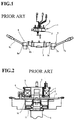
- the inflator is then electrically connected to electrical circuitry mounted on a car panel via a cable reel known as a rotary connector.
- the cable reel comprises an outer cylindrical body which constitutes a fixed body 2.
- the fixed body 2 is bound to combination switch bodies 3 linked to a steering column 4.
- the cable reel 1 also comprises a mobile body 5, which constitutes an inner cylindrical body.
- the mobile body 5 is mounted into the fixed body 2 in a freely rotatable way, and is further fitted into a steering wheel 10 so as to form a hollow torus.
- the hollow torus contains a flat cable 6 arranged in a spiral.
- One end of the flat cable 6 is fixed to the fixed body 2, whilst the other end thereof is fixed to the mobile body 5, so that the signals passing through the flat cable 6 can be transmitted to outside.
- the mobile body is rotated correspondingly clockwise or counter-clockwise.
- the flat cable 6 can follow the above rotation by winding or unwinding its spires.
- a mobile body 5 mounted in the cable reel 1 is fixed to the lower end (as viewed in Fig.2) of the steering wheel 10 through a lobe (not shown in the figures).
- the fixed body 2, into which the mobile body 5 is mounted in a freely rotatable way, is fixed on the upper face (as viewed in Fig.2) of the combination switch bodies 3, whilst the latter 3 are fixed to the steering column 4.
- the combination switch body 3 located on the right-hand side of the steering column (Fig.1) carries a turn indicator-signal unit 7 (winker or blinker unit) which comprises a turn indicator-signal housing 7a containing turn indicator-signal circuitry 7b such as a turn indicator-signal switch (winker switch).
- the combination switch body 3 located on the left-hand side of the steering column (Fig.1) carries a lighting unit 8 which comprises a lighting housing 8a containing lighting circuitry 8b such as a light switch.
- the turn indicator-signal unit 7 and the lighting unit 8 further comprise a turn indicator-signal lever 7c and a lighting lever 8c, both projecting outwardly from the respective housings 7a and 8a.
- One of the combination switch bodies 3 and a steering shaft 9 form a space under the cable reel 1. Accordingly, a cancel cam 10 and an encoder (steering angle sensor) 11 can be installed in this space, and mounted on the steering shaft 9.
- the turn indicator-signal unit 7, lighting unit 8, cable reel 1, cancel cam 10 and encoder 11 are provided as corresponding individual units, and assembled together at a subsequent stage. Accordingly, each unit requires a housing and mounting means, e.g. bolts, by which it is linked to the other units. As a result, the number of parts used tends to increase greatly.
- the housing for these units tends to increase the height, diametrical size and weight of the construction, as does the configuration in which the cable reel 1 is mounted on the combination switch bodies 3.
- the above units are supplied typically by different manufacturers. A sufficient degree of clearance must then be provided when these units are assembled. As a result, a space, otherwise unnecessary, must be taken into account, and the construction becomes more voluminous.
- a main object of the present invention is therefore to provide a structure requiring no unit-by-unit assembling.
- the structure of the integrated connector device is reduced to a minimum scale and weight, by modifying the mounting position of the cable reel.
- an integrated connector device comprising a cable reel and combined switch system.
- the integrated connector device further comprises a base shell including: a top wall portion with a central through-hole; an external sidewall portion extending downwardly from the top wall portion and having first and second lever notches; and first and second parting strip portions respectively provided at a predetermined distance from the external sidewall portion.
- the base shell has a central axis.
- the cable reel of the invention comprises a fixed body and a mobile body, and has a central axis.
- the combined switch systems of the invention comprise a turn indicator signal system and a lighting system respectively comprising turn indicator signal and lighting levers.
- the cable reel is then fitted into the base shell by joining the respective central axis, such that the fixed body is fitted between the first and second parting strip portions, the turn indicator-signal system being fitted between the external sidewall portion and the first parting strip portion, whilst the lighting system is fitted between the external sidewall portion and the second parting strip portion, and the turn indicator-signal and lighting levers are extended outwardly through the first and second lever notches.
- the mobile body of the cable reel contained in the base shell comprises an upper portion, and the upper portion carries a cancel cam integrally formed therewith.
- the mobile body of the cable reel contained in the base shell comprises a top wall portion
- the fixed body of the cable reel comprises an external sidewall portion
- the top wall portion of the mobile body carries a main scale portion integrally formed therewith.
- an encoder between the external sidewall portion of the fixed body and the external sidewall portion of the base shell, but biased from the positions where the turn indicator-signal and lighting systems are located, such that the encoder can detect the position of the main scale portion.
- the cable reel and the base shell are adapted to be joined to a steering shaft having a central axis, such that the central axis of the cable reel and base shell are joined with that of the steering shaft, and the turn indicator-signal system and the lighting system are placed at a predetermined position with respect to the central axis of the steering shaft.
- the invention comprises a base shell which contains a turn indicator-signal system including necessary functional parts, as well as a lighting system including necessary functional parts.
- These functional parts are no longer stored in separate housings as in the prior art, but incorporated into the base shell as an integral system thereof. The space necessary for the separate housings can thus be obviated.
- the cable reel is fitted into the inner side (central axis side of the base shell) of the first and second parting strip portions of the base shell, so that the height and width size of the integrated connector device is reduced, and the whole structure of the device becomes compact.
- turn indicator-signal system and the lighting system are not stored in separate housings as a unitary entity, so that functional parts for these systems can be added or modified very easily.
- the integrated connector device is configured such that the central axis of the base shell and that of the steering shaft are brought together, so that all members or systems to be incorporated into the base shell can be installed very easily at predetermined positions with respect to the central axis.
- the encoder preferably comprises a printed circuit board, and a sensor system connected thereto which includes a light-emitting element and a light-receiving element.
- a main scale is provided in a space formed between the light-emitting element and the light-receiving element, and rotated therein in conjunction with the mobile body, so that the steering angle can be detected. All these members are integrally molded in a resin.
- the cancel cam and the main scale are then integrally formed with the mobile body of the cable reel. Further, the encoder is disposed between the fixed body and the base shell, in ways that the structure of the integrated connector device is simplified and rendered more compact.
- Fig.3 is a top plan view of an integrated connector device 20 incorporating a cable reel and combined switch systems.
- Fig.4 is a cross-sectional side view taken along line IV-IV in the device of Fig.3.
- Fig.5 is a cross-sectional side view taken along line V-V in the device of Fig.3.
- the integrated connector device 20 of the invention comprises a base shell 21, which contains a cable reel 30, a turn indicator-signal system 22, a lighting system 23 and an encoder 24.
- the turn indicator-signal system 22 and the lighting system 23 are installed in the peripheral zones of base shell 21 substantially distal and opposed to each other, with respect to the central axis of the base shell 21.
- the encoder 24 is then installed in another peripheral zone of base shell 21, biased from those of the systems 22 and 23.
- the base shell 21 itself is constituted mainly of a top wall portion 21a, an external sidewall portion 21b and first and second parting strip portions 21c and 21d, as shown in Figs.4 to 6.
- the central zone of the top wall portion 21a is provided with a through-hole 21e (Fig.6).
- the top wall portion 21a of the base shell 21 further includes four peripheral corners located adjacent but outside the area where a torus-shaped cable reel is installed (see Fig.3). These four peripheral corners are formed into flange portions 21f adapted to fit to a steering column (not shown in the figures).
- the first and second parting strip portions 21c and 21d are respectively provided with a reel-locking hole 21g for fixing the cable reel 30, and a system-locking hole 21h for fixing the corresponding turn indicator-signal system 22 or lighting system 23.
- One side of the external sidewall portion 21b adjacent the turn indicator-signal system 22 is provided with a notch 21i for passing a turn indicator-signal lever 25, whilst the other side of the external sidewall portion 21b adjacent the lighting system 23 is provided with a similar notch 21j for passing a lighting lever 26.
- the turn indicator-signal system 22 is prepared by mounting functional turn indicator-signal parts together, and is provided with a system-locking claw 22a.
- the turn indicator-signal system is then inserted as a single unit into the space formed between the external sidewall portion 21b and the first parting strip portion 21c.
- the system-locking claw 22a is then passed through the system-locking hole 21h, and fixed thereto.
- the turn indicator-signal system 22 includes a board carrying circuit elements such as a turn indicator-signal switching circuit, and is connected to an end of a turn indicator-signal lever 25.
- the latter 25 projects outwardly from the base shell 21 through the turn indicator-signal notch 21i.
- the lighting system 23 is prepared by mounting functional lighting parts together, and is provided with a system-locking claw 23a.
- the lighting system 23 is then inserted as a single unit into the space formed between the external sidewall portion 21b and the second parting strip portion 21d.
- the system-locking claw 23a is then passed through the system-locking hole 21h, and fixed thereto.
- the lighting system 23 includes a circuit board carrying circuit elements such as a lighting switch circuit, and is connected to an end of a lighting lever 26. The latter 26 projects outwardly from the base shell 21 through the lighting notch 21j.
- the turn indicator-signal system 22 and the lighting system 23 are contained respectively in a separate housing. According to the invention, they are now directly contained in the base shell 21.
- the cable reel 30 is defined by a cable enclosure.
- the cable enclosure is substantially in the form of a hollow torus, which includes a bottom wall portion, an external sidewall portion, a top wall portion and an internal sidewall portion.
- the bottom wall portion and external sidewall portion of the hollow torus form the fixed body 31, whilst the top wall portion and internal sidewall portion of the hollow torus form the mobile body 32 (e.g. rotor).
- the cable enclosure thus defined contains a flat cable 33 in a spiral.
- the top wall portion forming part of the mobile body 32 comprises a cancel cam 34 (also refer to Figs.3 and 5), which is integrally formed therewith and extends upwardly therefrom.
- the top wall portion in the mobile body 32 comprises a main scale portion 35, which is integrally formed therewith and extends diametrically outwardly therefrom.
- the flat cable 33 is connected to a connector portion 37 through an electrical conductor 36 extending therefrom.
- the connector portion 37 is also formed integrally with the mobile body 32. The connector portion 37 can receive a cable terminal connected to the inflator of an airbag. The latter is thus connected to the electrical conductor 36.
- the fixed body 31, to which the mobile body 32 is mounted in a freely rotatable way, has an external sidewall portion 31a provided with locking claws 31b.
- the locking claws 31b lock with the reel-hole 21g formed in the first and second parting strip portions 21c and 21d.
- the encoder 24 is provided in a rear peripheral zone 21b-1, with respect to the driver's position, formed between the external sidewall portion 31a of the fixed body 31 (Fig.7A) and the external sidewall portion 21b of base-shell 21 (Figs.3 and 5).
- the encoder 24 includes a sensor 41 comprising a printed circuit board 40, and light-emitting and light-receiving elements 41a and 41b respectively connected thereto.
- the board and elements are integrally molded in a resin 42.
- the main scale 35 is rotated in conjunction with the mobile body 32 in the space 41c formed between the light-emitting element 41a and the light-receiving element 41b, so that the steering angle can be detected.
- the integrated connector device 20 includes a base shell 21 comprising a first parting strip portion and a second parting strip portion, a bottom opening being provided with a central axis.
- the base shell 21 and the cable reel 30 have respective central axes.
- the cable reel 30 is then mounted into the base shell 20 from beneath, with the respective aligned central axes.
- the cable reel 30 is thus contained between the first and second parting strip portions, and locked therein.
- a turn indicator-signal system 22 is mounted between the first parting strip portion 21c and the external sidewall portion 21b of the base shell 21 from the bottom opening thereof.
- a lighting system 23 is mounted between the second parting strip portion 21d and the external sidewall portion 21b of the base shell 21 from the bottom opening thereof.
- Both systems are then easily fixed with the corresponding parting strip portions 21c and 21d by locking.
- An encoder 24 is initially fitted onto the cable reel 30 from outside its periphery, and mounted into the base shell 21 together with the cable reel 30. All the above members, together with the base shell 21, are subsequently fixed to a steering column by bolts.
- the cable reel 30 is placed on the same horizontal level as the turn indicator-signal system 22 and the lighting system 23. Furthermore, the cancel cam 34 and the encoder 24 are placed on the same height level as the cable reel 30. Accordingly, the height of the integrated connector device 20 can be reduced. Further, the turn indicator-signal system 22 and the lighting system 23 are contained in the base shell 21, instead of in separate housings, so that the whole device can be miniaturized and rendered more compact, and requires a smaller space.
- the base shell 21 is fixed to the steering column (refer to Fig.2), whilst the mobile body 32 of the cable reel 30, contained in the base shell 21, is fixed to the steering shaft.
- the integrated connector device comprising a cable reel and combined switch systems according to the invention
- the systems that were classically contained in separate housings are now stored in the base shell, so that the separate housings are no longer required, and the necessary space can be reduced.
- a certain degree of clearance becomes necessary between the housings . As this clearance can be eliminated, the space necessary for a unitary connector device can be reduced.
- the base shell of the invention contains a cable reel, a turn indicator-signal system, a lighting system, a cancel cam and an encoder all together. Accordingly, the height and width size of the device can be reduced, and the device is miniaturized and rendered lighter.
Landscapes
- Engineering & Computer Science (AREA)
- Mechanical Engineering (AREA)
- Switches With Compound Operations (AREA)
- Steering Controls (AREA)
- Electric Cable Arrangement Between Relatively Moving Parts (AREA)
- Connector Housings Or Holding Contact Members (AREA)
- Details Of Connecting Devices For Male And Female Coupling (AREA)
Applications Claiming Priority (2)
| Application Number | Priority Date | Filing Date | Title |
|---|---|---|---|
| JP2000109858 | 2000-04-11 | ||
| JP2000109858A JP2001294104A (ja) | 2000-04-11 | 2000-04-11 | ケーブルリールとコンビスイッチとの一体型電装品 |
Publications (2)
| Publication Number | Publication Date |
|---|---|
| EP1145915A2 true EP1145915A2 (de) | 2001-10-17 |
| EP1145915A3 EP1145915A3 (de) | 2004-01-28 |
Family
ID=18622474
Family Applications (1)
| Application Number | Title | Priority Date | Filing Date |
|---|---|---|---|
| EP01400916A Withdrawn EP1145915A3 (de) | 2000-04-11 | 2001-04-10 | Integrierter Verbinder mit einer Kabeltrommel und Schalter |
Country Status (3)
| Country | Link |
|---|---|
| US (1) | US6501034B2 (de) |
| EP (1) | EP1145915A3 (de) |
| JP (1) | JP2001294104A (de) |
Families Citing this family (7)
| Publication number | Priority date | Publication date | Assignee | Title |
|---|---|---|---|---|
| DE19958505C2 (de) * | 1999-12-04 | 2003-04-10 | Delphi Tech Inc | Lenkstockschalteranordnung |
| DE20003965U1 (de) * | 2000-02-24 | 2000-07-13 | Petri Ag, 63743 Aschaffenburg | Einrichtung zur Übertragung elektrischen Stroms zwischen zwei zueinander verdrehbaren Bauelementen einer Lenkeinrichtung für Kraftfahrzeuge |
| DE10019795B4 (de) * | 2000-04-20 | 2004-09-30 | Delphi Technologies, Inc. (n.d.Ges.d. Staates Delaware), Troy | Lenkstockschalter |
| JP4752437B2 (ja) * | 2004-12-27 | 2011-08-17 | 株式会社アドヴィックス | 車両用センサ装置を用いた車両安定化システム |
| JP4582084B2 (ja) * | 2006-12-05 | 2010-11-17 | 住友電装株式会社 | シーソースイッチ |
| FR2984818B1 (fr) * | 2011-12-23 | 2015-12-11 | Sc2N Sa | Module de communication de colonne de direction |
| CN114946805B (zh) * | 2022-06-14 | 2023-04-18 | 清华大学 | 一种激光光纤除草除虫系统 |
Family Cites Families (11)
| Publication number | Priority date | Publication date | Assignee | Title |
|---|---|---|---|---|
| JPH0976826A (ja) * | 1995-09-08 | 1997-03-25 | Niles Parts Co Ltd | 車両用回転コネクタのネジ止め構造 |
| JP3117632B2 (ja) * | 1995-11-24 | 2000-12-18 | ナイルス部品株式会社 | 回転コネクタとスイッチとの取付構造 |
| JP3333387B2 (ja) * | 1996-05-29 | 2002-10-15 | ナイルス部品株式会社 | スイッチの取付構造 |
| KR100318040B1 (ko) * | 1996-08-05 | 2002-04-22 | 가타오카 마사타카 | 회전커넥터의설치구조와회전커넥터및이를사용한스티어링유닛 |
| JPH1064647A (ja) | 1996-08-26 | 1998-03-06 | Yazaki Corp | 舵角センサ付コネクタ及びそれを用いたコラム構造 |
| JPH10241504A (ja) * | 1997-02-24 | 1998-09-11 | Yazaki Corp | ステアリング用信号伝達装置 |
| JPH11191346A (ja) * | 1997-12-26 | 1999-07-13 | Niles Parts Co Ltd | 回転コネクタ付きコラムスイッチ |
| JP3535970B2 (ja) | 1998-04-13 | 2004-06-07 | 古河電気工業株式会社 | コラムスイッチ装置 |
| JP2000003638A (ja) * | 1998-06-15 | 2000-01-07 | Sumitomo Wiring Syst Ltd | ケーブルリールとコンビネーションスイッチとの取付構造 |
| JP2001006493A (ja) * | 1999-06-16 | 2001-01-12 | Sumitomo Wiring Syst Ltd | ステアリングシャフトへのケーブルリールとウインカ・ライテイングスイッチの取付構造 |
| DE19933048A1 (de) * | 1999-07-15 | 2001-01-18 | Valeo Schalter & Sensoren Gmbh | Lenkstockmodul mit Lenkwinkelsensor und kompakter Bauweise |
-
2000
- 2000-04-11 JP JP2000109858A patent/JP2001294104A/ja not_active Abandoned
-
2001
- 2001-04-10 US US09/828,964 patent/US6501034B2/en not_active Expired - Fee Related
- 2001-04-10 EP EP01400916A patent/EP1145915A3/de not_active Withdrawn
Also Published As
| Publication number | Publication date |
|---|---|
| JP2001294104A (ja) | 2001-10-23 |
| EP1145915A3 (de) | 2004-01-28 |
| US20010027913A1 (en) | 2001-10-11 |
| US6501034B2 (en) | 2002-12-31 |
Similar Documents
| Publication | Publication Date | Title |
|---|---|---|
| US5936215A (en) | Steering roller connector signal transmission device on a steering wheel column | |
| EP0771693B1 (de) | Multifunktionsschalter mit Drehverbinder | |
| US6364676B2 (en) | Device for transmitting energy | |
| EP0968883B1 (de) | Lenksäulenschalter | |
| US7134360B2 (en) | Vehicle steering wheel | |
| US6548773B2 (en) | Column mounted turn signal, wiper-washer switch | |
| US6583373B2 (en) | Steering column module | |
| US6601443B1 (en) | Integrated subassembly mountable on the steering column or on the steering wheel of a motor vehicle | |
| US6501034B2 (en) | Integrated connector device including a cable reel and combined switch systems | |
| EP0861753B1 (de) | Schalterkombination | |
| US20020059838A1 (en) | Structure for mounting steering angle sensor for steering | |
| JP5426259B2 (ja) | ステアリングモジュール | |
| EP1149730B1 (de) | Schaltereinheit für ein Kraftfahrzeuglenkrad | |
| EP1145917A2 (de) | Verbinderstruktur mit einer Kabeltrommel und kombiniertes Schaltersystem | |
| JP3518662B2 (ja) | 回転コネクタ | |
| US6956177B2 (en) | Signal transmitting device for steering column assembly | |
| EP1036713A2 (de) | Drehverbinder der fähig ist nach einem Rotationstest leicht und zuverlässig ein bewegbares Gehäuse in einer neutralen Rotationsposition zu verriegeln | |
| JP3424904B2 (ja) | ステアリング装置 | |
| JPH09207787A (ja) | 車両のステアリングモジュール | |
| JP2000304522A (ja) | ステアリングロールコネクタ | |
| JP2586051Y2 (ja) | 車両用ターンシグナルスイッチの構造 | |
| EP1233887B1 (de) | Lenkstangenanordnung | |
| JP2000118295A (ja) | コンビネーションスイッチ |
Legal Events
| Date | Code | Title | Description |
|---|---|---|---|
| PUAI | Public reference made under article 153(3) epc to a published international application that has entered the european phase |
Free format text: ORIGINAL CODE: 0009012 |
|
| 17P | Request for examination filed |
Effective date: 20010414 |
|
| AK | Designated contracting states |
Kind code of ref document: A2 Designated state(s): AT BE CH CY DE DK ES FI FR GB GR IE IT LI LU MC NL PT SE TR |
|
| AX | Request for extension of the european patent |
Free format text: AL;LT;LV;MK;RO;SI |
|
| PUAL | Search report despatched |
Free format text: ORIGINAL CODE: 0009013 |
|
| AK | Designated contracting states |
Kind code of ref document: A3 Designated state(s): AT BE CH CY DE DK ES FI FR GB GR IE IT LI LU MC NL PT SE TR |
|
| AX | Request for extension of the european patent |
Extension state: AL LT LV MK RO SI |
|
| STAA | Information on the status of an ep patent application or granted ep patent |
Free format text: STATUS: THE APPLICATION HAS BEEN WITHDRAWN |
|
| 18W | Application withdrawn |
Effective date: 20040615 |