EP1145954B1 - Dispositif et procédé pour la réduction des tourbillons de sillage à l'arrière des avions à l'approche de l'atterissage - Google Patents
Dispositif et procédé pour la réduction des tourbillons de sillage à l'arrière des avions à l'approche de l'atterissage Download PDFInfo
- Publication number
- EP1145954B1 EP1145954B1 EP01108685A EP01108685A EP1145954B1 EP 1145954 B1 EP1145954 B1 EP 1145954B1 EP 01108685 A EP01108685 A EP 01108685A EP 01108685 A EP01108685 A EP 01108685A EP 1145954 B1 EP1145954 B1 EP 1145954B1
- Authority
- EP
- European Patent Office
- Prior art keywords
- wing
- vortex
- additional flap
- flap
- aircraft
- Prior art date
- Legal status (The legal status is an assumption and is not a legal conclusion. Google has not performed a legal analysis and makes no representation as to the accuracy of the status listed.)
- Expired - Lifetime
Links
Images
Classifications
-
- B—PERFORMING OPERATIONS; TRANSPORTING
- B64—AIRCRAFT; AVIATION; COSMONAUTICS
- B64C—AEROPLANES; HELICOPTERS
- B64C23/00—Influencing air flow over aircraft surfaces, not otherwise provided for
- B64C23/06—Influencing air flow over aircraft surfaces, not otherwise provided for by generating vortices
-
- Y—GENERAL TAGGING OF NEW TECHNOLOGICAL DEVELOPMENTS; GENERAL TAGGING OF CROSS-SECTIONAL TECHNOLOGIES SPANNING OVER SEVERAL SECTIONS OF THE IPC; TECHNICAL SUBJECTS COVERED BY FORMER USPC CROSS-REFERENCE ART COLLECTIONS [XRACs] AND DIGESTS
- Y02—TECHNOLOGIES OR APPLICATIONS FOR MITIGATION OR ADAPTATION AGAINST CLIMATE CHANGE
- Y02T—CLIMATE CHANGE MITIGATION TECHNOLOGIES RELATED TO TRANSPORTATION
- Y02T50/00—Aeronautics or air transport
- Y02T50/10—Drag reduction
Definitions
- the invention relates to an aircraft with at least one device and a method for reducing Caster vortexes behind aircraft that are approaching landing, which Aircraft to generate lift a right and a left wing having high lift systems according to the preamble of claim 1.
- high-lift systems are necessary in order to for example, on approach to generate the necessary lift.
- Such high-lift systems usually consist of slats and Landing flaps.
- a wing creates lift, it arises behind the wing always a wake with vortices. It initially forms in Area of the outer end of each flap a flap vortex as well a vertebra in the wing tip area.
- This vortex system rotates around each other, at the same time, the individual vertebrae rotate around themselves, the whole Vortex system carried away in a spiral movement with the flow becomes.
- the vortices generated by large transport aircraft pose a danger for subsequent air traffic, especially on the densely flown Arrival routes.
- Prescribed safety distances between approaching Airplanes reduce the risk, but also limit the capacity of one Runway, because the necessary horizontal to maintain flight safety
- the distance between the landing aircraft increases, the larger or heavier the Airplanes become and the vortex intensity depends on the weight of an airplane.
- a use of new generation large aircraft, for example an A3XX, as well as the growing air traffic demand a reduction the generously dimensioned safety distances.
- the goal is therefore aimed at measures on the aircraft, the wake vortices reduce and promote their premature dissolution.
- the present invention is therefore based on the object of a generic To train aircraft and a generic method so that Trailing vortices behind aircraft that are approaching landing are reduced and an early dissolution of such vortices is promoted.
- the additional flap according to the invention as a simple and effective Measure applicable. It is as a simple little component and can be easily attached to the wing when not in use accommodate.
- the sub-claim 2 shows the advantageous attachment point on the wing.
- the sub-claims 3 and 4 give the for the effect as a vortex generator advantageous angle of attack of the additional flap.
- Formations of the additional flap are specified in subclaims 5 to 8, which a controlled leading edge vertebra to form an interfering vortex on the Generate additional flap.
- the Additional flap has the shape of a delta wing, two arise in opposite directions rotating vertebrae as a pair of vertebrae that form the disturbing vortex.
- Claims 9 to 11 are directed to an aircraft, the possible Arrangements of the device according to the invention on the aircraft wings are specified.
- sub-claim 13 are the process steps for reducing the vortex strength of the wake vortex indicated.
- the subclaims 14 to 15 give alternative procedures for operation of the additional flaps according to the invention on an aircraft.
- FIGS. 1 to 5 In the drawing, embodiments of the invention are shown, the following are described in more detail with reference to FIGS. 1 to 5.
- FIGS. 1 to 5 In the figures are Identical components with the same reference numerals.
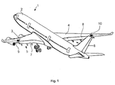
- FIG. 1 An aircraft 1 can be seen in a perspective view in FIG. 1.
- the plane 1 is as a subsonic transport plane, especially for transportation provided by passengers.
- Each wing 3 or 4 points to generating the necessary lift during slow flight, for example on approach, high-lift systems 5 and 6 respectively.
- Such high-lift systems 5 and 6 have flaps 7 and 8, among other things.
- On Each wing 3 and 4 is an inventive device 9 and 10 for Reduction of wake vortices provided, their arrangement, shape and Mode of operation is described in more detail in the following figures.
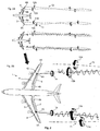
- FIGS. 2A and 2B planes with trailing vortices are shown in a view from above.
- a basic configuration of the aircraft 1 can be seen in FIG. 2A, the wake vortices 11 and 12, which essentially arise on the left wing 3 and on the right wing 4, being recognizable by means of arrows by indicating their course and their direction of rotation.
- a flap vortex 11B or 12B is formed on the wing trailing edge 3B or 4B in the region of the swirling flow converging on the trailing edge of the wing.
- the "weak point" of the swirling flow is the outer end 7A or 8A of the extended landing flap 7 of the wing 3 or the landing flap 8 of the wing 4 in the spanwise direction B or 12B is essentially the large vortex that brings with it the disadvantages already mentioned for subsequent air traffic.
- a controlled generated interference flow is introduced into the process of creating the wake flow. This already disrupts the creation of the dangerous eddy current.
- the device for reducing wake vortices 9 or 10 - referred to in the following additional flap 9 or 10 - is provided, which is located on the wing 3 or 4 in the region of the flap end 7A or 8A of the landing flaps 7 or 8 is arranged.
- the (controlled, generated small) interference vortex 13 or 14 interferes with the converging vertebrae from the trailing edge of the wing 3B or 4B, ie essentially with the valve vortex 11B or 12B.
- the mode of operation of an interfering vortex 13 or 14 is explained in more detail below:
- the additional surface (vortex generator) 9 or 10 which is preferably set at 15 to 25 degrees (relative to the retracted state), produces a controlled leading edge vortex on its suction side, which results from detached flow of the Leading edge is fed.
- This vortex leaves the additional surface 9 or 10 at its rear edge and interferes as a free interfering vortex 13 or 14 with the valve vortex 11B or 12B, which is in the process of developing at the valve end 7A or 8A (by convergence of vortex strength, which along the rear edge as unstable fluidized bed flows out).
- the effect is so intense that the resulting valve vortex 11B or 12B is made to vibrate transversely and is considerably disturbed in its concentration process.
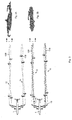
- the valve vortex 11B or 12B loses strength, the maximum vortex strength in the core of the resulting vortex being reduced considerably, which can be clearly seen in FIG. 3, in particular in FIG. 3B.
- 3B shows the vortex intensity of the wake vortex 12 shown by way of example, the flap vortex 12B being strongly oscillating and therefore reduced in intensity as a result of the disturbing vortex 14.
- a vortex 12 disturbed in this way disintegrates prematurely.
- 3A shows the vortex intensity of wake vortices of an aircraft without a device 9 or 10 according to the invention.
- the wake vertebra 11 or 12 of such an aircraft has a pronounced core, which expresses the tip in the middle of the vortex. The higher this tip, the greater the intensity of the vertebra.
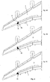
- FIGS. 4A to 4C shows embodiments of the additional flap 9 according to the invention (also corresponds to the additional flap 10 on the wing 4) in FIGS. 4A to 4C.
- the relatively small additional flap 9 is attached with its base 9 'on the wing 3 in the area of the flap end 7A of the landing flap 7, preferably in 60% to 80% of the profile depth of the base wing, the profile depth being a cut in the direction of flight through the base wing.
- the base point 9 'of the additional flap 9 lies in an area which, measured from the end of the flap 7A, extends on both sides to the left or right in each case 10% of the half-span.
- the half-span is the distance from the center of the fuselage to the wing tip.
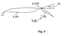
- the additional flap 9 must be placed in the flow for the duration of its action, the preferred setting angle being shown in FIG. 5.
- the additional flap 9 is shaped in such a way that a controlled (small) vortex is formed on its front edge, which represents a high turbulent vortex flow when leaving the additional flap 9.
- This high-energy flow leaves the additional flap 9 and penetrates into the "weak point" of the resulting wake flow, ie it stimulates the wake vortex to intensive vibrations and thereby suppresses the concentration process, which would otherwise lead to a strong wake vortex 11.
- the additional flap 9 (or 10) acts as a passive component, ie it is extended and remains stationary during the approach.
- the additional flap 9 has the shape 9A of a wing of small extension with approximately 60 degrees leading edge sweep on one side on the left. The other side is preferably unswept. 48 shows another possible form 9B.
- the additional flap 9 is formed here as a wing with a small extension with approximately 60 degrees leading edge sweep on one side on the right, the other side is unswept.
- a third embodiment 9C is shown in Fig. 4C. This embodiment 9C is characterized by a wing of small extension with approximately 60 degrees leading edge sweep on both sides (delta wing).
- a delta wing as an additional flap, two vortices rotating in opposite directions are created as a pair of vertebrae, which are supposed to interfere with the formation of the wake vortex in a controlled manner. All three embodiments have in common that the swept front edges are sharpened like a knife edge in order to force the stall.
- the swept front edges are preferably straight, but can also be curved, similar to the wing of the Concorde supersonic aircraft.
- the rear edge of the additional flap 9A, 9B or 9C is preferably straight and is preferably perpendicular to the direction of flight.
- the flaps 7 and 8 as part of the high-lift system 5 and 6 can be seen.
- the additional flap 9 or 10 is used for the approach extended, the setting angle 15 of the additional flap 9 or 10 opposite the top of the wing 3 or 4 preferably between 12 to 25 degrees should be. If the angle of attack is above 30 degrees, it can result in a uncontrolled stall, which is especially for the formation of the controlled vortex 13 or 14 is undesirable.
Landscapes
- Engineering & Computer Science (AREA)
- Aviation & Aerospace Engineering (AREA)
- Toys (AREA)
- Aerodynamic Tests, Hydrodynamic Tests, Wind Tunnels, And Water Tanks (AREA)
- Traffic Control Systems (AREA)
- Turbine Rotor Nozzle Sealing (AREA)
- Structures Of Non-Positive Displacement Pumps (AREA)
- Radar Systems Or Details Thereof (AREA)
Claims (15)
- Avion avec dispositif de réduction des tourbillons de sillage (11, 12) à l'arrière d'avions, l'avion (1) présentant, pour produire la sustentation, des ailes porteuses droite et gauche (3, 4) comprenant notamment des volets hypersustentateurs (7, 8) en tant que systèmes d'hypersustentation (5, 6), le dispositif étant constitué d'un générateur de tourbillons (9, 10) destiné à produire un tourbillon perturbateur (13, 14) et disposé contre contre l'aile porteuse concernée (3, 4), dans la zone du bord arrière de l'aile (3B, 4B), à proximité de l'extrémité extérieure déployée du volet hypersustentateur (7A, 8A), dont le pied (9') a été prévu contre l'aile porteuse (3, 4), à gauche et à droite de l'extrémité externe concernée du volet hypersustentateur (7A, 8A), dans une amplitude correspondant à 10 % de la moitié de la travée, caractérisé en ce que le volet supplémentaire (9, 10) pour le vol lent adopte une position déployée et peut, lorsqu'il n'est pas utilisé, être rabattu dans l'aile, en ce que le bord arrière du volet supplémentaire (9, 10) a été, également en position déployée, orientée de manière essentiellement parallèlement à la direction d'écartement du vaigrage de l'aile, et de manière essentiellement perpendiculaire à la direction de vol et en ce que la surface du volet supplémentaire (9, 10) possède, dans la direction de l'écoulement, une flèche sur le bord avant, à droite, à gauche ou des deux côtés, pour, dans la position déployée, produire un tourbillon contrôlé sur les bords avant fléchés.
- Avion selon la revendication 1, caractérisé en ce que le pied du volet supplémentaire (9, 10) a été, prévu dans le sens de la profondeur, à partir de 60 % de la profondeur de sculpture de l'aile porteuse (3, 4).
- Avion selon une des revendications 1 ou 2, caractérisé en ce que le volet supplémentaire (9, 10) présente, en position déployée, un angle d'incidence (15) de moins de 30 degrés par rapport au plan de la face supérieure de l'aile.
- Avion selon la revendication 3, caractérisé en ce que l'angle d'incidence (15) est compris entre 12 et 25 degrés.
- Avion selon une des revendications 1 à 4, caractérisé en ce que le volet supplémentaire (9, 10) se présente sous la forme (9A) d'une aile à allongement réduit avec un fléchage des bords avant de 60 % environ, à gauche, l'autre face n'étant pas fléchée.
- Avion selon une des revendications 1 à 4, caractérisé en ce que le volet supplémentaire (9, 10) se présente sous la forme (9B) d'une aile à allongement réduit avec un fléchage des bords avant de 60 % environ, à droite, l'autre face n'étant pas fléchée.
- Avion selon une des revendications 1 à 4, caractérisé en ce que le volet supplémentaire (9, 10) se présente sous la forme (9C) d'une aile à allongement réduit avec un fléchage des bords avant de 60 % environ, des deux côtés.
- Avion selon une des revendications 5 à 7, caractérisé en ce qu'au moins un bord avant fléché du volet supplémentaire (9A, 9B ou 9C) est effilé et le bord arrière du volet additionnel (9A, 9B ou 9C) est de préférence rectiligne.
- Avion selon une des revendications précédentes, caractérisé en ce que le volet additionnel (9, 10) adopte, pour agir pendant le vol lent, une position déployée stationnaire et cette position a été prévue symétriquement par rapport à chaque aile porteuse (3, 4).
- Avion selon une des revendications 1 à 8, caractérisé en ce que, pour agir pendant le vol lent, le volet supplémentaire (9, 10) oscille de façon dynamique entre une position rentrée et une position déployée, le mouvement étant symétrique des deux côtés des ailes porteuses (3, 4).
- Avion selon une des revendications 1 à 8, caractérisé en ce que, pour agir pendant le vol lent, le volet supplémentaire (9, 10) oscille de façon dynamique entre une position rentrée et une position déployée, le mouvement étant asymétrique des deux côtés des ailes porteuses (3, 4).
- Procédé de réduction des tourbillons de sillage (11, 12) à l'arrière des avions, grâce auquel un tourbillon perturbateur (13, 14) est généré pour chaque aile porteuse (3, 4) à l'aide d'un volet supplémentaire (9, 10), un tourbillon étant produit sous la forme d'un tourbillon perturbateur (13, 14) contre le bord avant du volet supplémentaire (9, 10), sur le côté d'aspiration et étant inséré de manière ciblée dans la zone de formation d'un écoulement (11B, 12B) tourbillonnaire convergeant contre le bord arrière de l'aile (3B, 4B) et le tourbillon perturbateur (13, 14) interférant avec un tourbillon à volets (11B, 12B) faisant partie du processus de formation, pénétrant dans ce dernier et faisant osciller ce dernier de manière intensive et de telle sorte à réduire la force tourbillonnaire.
- Procédé selon la revendication 12, caractérisé en ce que, pour agir pendant le vol lent, le volet supplémentaire (9, 10) est déployé et adopte une position déployée, stationnaire et symétrique par rapport à chaque aile porteuse (3, 4)
- Procédé selon la revendication 12, caractérisé en ce que, pour agir pendant le vol lent, le. volet supplémentaire (9, 10) oscille de façon dynamique entre une position rentrée et une position déployée, le mouvement étant symétrique contre les ailes porteuses (3, 4), des deux côtés.
- Procédé selon la revendication 12, caractérisé en ce que, pour agir pendant le vol lent, le volet supplémentaire (9, 10) oscille de façon dynamique entre une position rentrée et une position déployée, le mouvement étant asymétrique contre les ailes porteuses (3, 4), des deux côtés.
Applications Claiming Priority (2)
| Application Number | Priority Date | Filing Date | Title |
|---|---|---|---|
| DE10018389 | 2000-04-13 | ||
| DE10018389A DE10018389C2 (de) | 2000-04-13 | 2000-04-13 | Vorrichtung sowie Verfahren zur Reduzierung von Nachlaufwirbeln hinter Flugzeugen im Landeanflug |
Publications (2)
| Publication Number | Publication Date |
|---|---|
| EP1145954A1 EP1145954A1 (fr) | 2001-10-17 |
| EP1145954B1 true EP1145954B1 (fr) | 2004-06-30 |
Family
ID=7638644
Family Applications (1)
| Application Number | Title | Priority Date | Filing Date |
|---|---|---|---|
| EP01108685A Expired - Lifetime EP1145954B1 (fr) | 2000-04-13 | 2001-04-06 | Dispositif et procédé pour la réduction des tourbillons de sillage à l'arrière des avions à l'approche de l'atterissage |
Country Status (7)
| Country | Link |
|---|---|
| US (1) | US6513761B2 (fr) |
| EP (1) | EP1145954B1 (fr) |
| AT (1) | ATE270217T1 (fr) |
| DE (2) | DE10018389C2 (fr) |
| ES (1) | ES2223674T3 (fr) |
| RU (1) | RU2268844C2 (fr) |
| UA (1) | UA72744C2 (fr) |
Families Citing this family (28)
| Publication number | Priority date | Publication date | Assignee | Title |
|---|---|---|---|---|
| FR2821605B1 (fr) * | 2001-03-01 | 2003-05-30 | Eads Airbus Sa | Procede et dispositif pour accelerer la destruction d'au moins deux vortex dans le sillage d'un mobile, en particulier d'un avion |
| US20050103944A1 (en) * | 2003-07-11 | 2005-05-19 | Us Of America As Represented By The Administrator Of The National Aeronautics & Space Administration | Trailing vortex management via boundary layer separation control |
| US20050061921A1 (en) * | 2003-09-19 | 2005-03-24 | Egolf Thomas A. | Aerodynamic tip protuberances for tip vortex intensity reduction |
| US6799739B1 (en) | 2003-11-24 | 2004-10-05 | The Boeing Company | Aircraft control surface drive system and associated methods |
| US8016244B2 (en) * | 2004-02-20 | 2011-09-13 | The Boeing Company | Active systems and methods for controlling an airfoil vortex |
| US7661629B2 (en) * | 2004-02-20 | 2010-02-16 | The Boeing Company | Systems and methods for destabilizing an airfoil vortex |
| US7100875B2 (en) * | 2004-02-20 | 2006-09-05 | The Boeing Company | Apparatus and method for the control of trailing wake flows |
| US7134631B2 (en) * | 2004-06-10 | 2006-11-14 | Loth John L | Vorticity cancellation at trailing edge for induced drag elimination |
| EP1746024B1 (fr) * | 2005-07-22 | 2007-11-07 | Airbus Deutschland GmbH | Procédé de contrôle d'un avion en vol |
| US7500641B2 (en) * | 2005-08-10 | 2009-03-10 | The Boeing Company | Aerospace vehicle flow body systems and associated methods |
| US7611099B2 (en) * | 2005-09-07 | 2009-11-03 | The Boeing Company | Seal assemblies for use with drooped spoilers and other control surfaces on aircraft |
| US7708231B2 (en) * | 2005-11-21 | 2010-05-04 | The Boeing Company | Aircraft trailing edge devices, including devices having forwardly positioned hinge lines, and associated methods |
| US7578484B2 (en) * | 2006-06-14 | 2009-08-25 | The Boeing Company | Link mechanisms for gapped rigid krueger flaps, and associated systems and methods |
| US7644892B1 (en) | 2006-07-06 | 2010-01-12 | Alford Jr Lionel D | Blended winglet |
| BRPI0603262B1 (pt) * | 2006-08-08 | 2021-02-23 | Yaborã Indústria Aeronáutica S.A | asa de aeronave incluindo um slat no bordo de ataque da asa e um fence rígido preso a uma porção estruturalmente rígida não móvel da asa |
| US7686253B2 (en) * | 2006-08-10 | 2010-03-30 | The Boeing Company | Systems and methods for tracing aircraft vortices |
| GB0716199D0 (en) * | 2007-08-20 | 2007-09-26 | Airbus Uk Ltd | Aircraft wing spoiler arrangement |
| US8061646B2 (en) * | 2007-09-14 | 2011-11-22 | Aurora Flight Sciences Corporation | Wing tip docking system for aircraft |
| FR2922189B1 (fr) * | 2007-10-16 | 2009-12-18 | Airbus France | Procede et dispositif pour diminuer les vitesses induites dans des tourbillons de sillage d'un avion. |
| WO2009101461A1 (fr) | 2008-02-12 | 2009-08-20 | Bombardier Inc. | Configuration de bec de bord d'attaque améliorée pour aéronef à voilure fixe |
| JP5286527B2 (ja) | 2009-07-13 | 2013-09-11 | 三菱重工業株式会社 | 高揚力発生装置、翼および高揚力発生装置の騒音低減装置 |
| US20170088254A1 (en) * | 2011-03-10 | 2017-03-30 | RuiQing Hong | Ultra-High-Pressure Fluid Injection Dynamic Orbit-Transfer System and Method |
| EP3020964B8 (fr) * | 2014-11-13 | 2019-06-19 | Siemens Gamesa Renewable Energy A/S | Guidage d'un éclair vers un récepteur de foudre |
| CN104895876B (zh) * | 2015-05-22 | 2018-01-16 | 厦门大学 | 一种基于径向不稳定性的加速漩涡破裂的方法 |
| EP3150486B1 (fr) * | 2015-10-01 | 2018-03-14 | Airbus Operations GmbH | Dispositif de génération de tourbillons, système de commande d'écoulement et procédé pour commander un écoulement sur une surface de gouvernail |
| US10318904B2 (en) | 2016-05-06 | 2019-06-11 | General Electric Company | Computing system to control the use of physical state attainment of assets to meet temporal performance criteria |
| CN112810803A (zh) * | 2021-02-22 | 2021-05-18 | 中国民用航空飞行学院 | 一种用于加快翼尖涡耗散的飞机尾流调整装置 |
| CN116424544B (zh) * | 2023-06-14 | 2023-08-15 | 清华大学 | 飞机襟翼 |
Family Cites Families (23)
| Publication number | Priority date | Publication date | Assignee | Title |
|---|---|---|---|---|
| US2925232A (en) * | 1957-06-05 | 1960-02-16 | Boeing Co | Airplane spoiler assembly |
| US3578264A (en) | 1968-07-09 | 1971-05-11 | Battelle Development Corp | Boundary layer control of flow separation and heat exchange |
| US3596854A (en) | 1969-06-09 | 1971-08-03 | William R Haney Jr | Vortex generator for airfoil structures |
| US3881669A (en) * | 1973-05-16 | 1975-05-06 | Martin Lessen | Method and apparatus for elimination of airfoil trailing vortices |
| US3997132A (en) * | 1974-12-11 | 1976-12-14 | The Garrett Corporation | Method and apparatus for controlling tip vortices |
| US4039161A (en) | 1975-10-16 | 1977-08-02 | Mcdonnell Douglas Corporation | Hidden vortex generators |
| GB2051706A (en) | 1979-06-19 | 1981-01-21 | British Aerospace | Aircraft wings |
| US4466586A (en) * | 1980-03-10 | 1984-08-21 | The Boeing Company | Directional control device for aircraft |
| GB8314656D0 (en) * | 1983-05-26 | 1983-06-29 | Secr Defence | Aircraft control |
| DE3521329A1 (de) * | 1985-06-14 | 1986-12-18 | Messerschmitt-Bölkow-Blohm GmbH, 8012 Ottobrunn | Wirbelgeneratoren- und grenzschichtabweiseranordnung |
| US4739957A (en) * | 1986-05-08 | 1988-04-26 | Advanced Aerodynamic Concepts, Inc. | Strake fence flap |
| US4776535A (en) | 1986-12-29 | 1988-10-11 | United Technologies Corporation | Convoluted plate to reduce base drag |
| RU2053928C1 (ru) * | 1988-09-20 | 1996-02-10 | Шведов Владимир Тарасович | Генератор вихря |
| US5058837A (en) * | 1989-04-07 | 1991-10-22 | Wheeler Gary O | Low drag vortex generators |
| US5253828A (en) | 1992-07-17 | 1993-10-19 | The Board Of Regents Of The University Of Oklahoma | Concealable flap-actuated vortex generator |
| US5749546A (en) | 1995-07-10 | 1998-05-12 | The Boeing Company | Method and apparatus for reducing airframe aerosound |
| US5788191A (en) * | 1995-08-18 | 1998-08-04 | Sikorsky Aircraft Corporation | Half-plow vortex generators for rotor blades for reducing blade-vortex interaction noise |
| US5772155A (en) | 1996-06-01 | 1998-06-30 | Nowak; Dieter K. | Aircraft wing flaps |
| US6042059A (en) * | 1997-02-20 | 2000-03-28 | Continuum Dynamics, Inc. | System and method of vortex wake control using vortex leveraging |
| DE19719922C1 (de) | 1997-05-13 | 1998-11-12 | Daimler Benz Aerospace Airbus | Einrichtung zur Beeinflussung einer Wurzelströmung |
| US6082679A (en) | 1997-06-26 | 2000-07-04 | The Boeing Company | Active system for early destruction of trailing vortices |
| US5983944A (en) | 1998-03-20 | 1999-11-16 | Niv; Shaul E. | Apparatus for active fluid control |
| DE19909190C2 (de) * | 1999-03-03 | 2001-02-22 | Deutsch Zentr Luft & Raumfahrt | Flugzeug mit mindestens einem Wirbelgenerator je Tragflügel zum Reduzieren der Wirbelstärke der Flügelhauptwirbel |
-
2000
- 2000-04-13 DE DE10018389A patent/DE10018389C2/de not_active Expired - Fee Related
-
2001
- 2001-01-25 US US09/770,763 patent/US6513761B2/en not_active Expired - Fee Related
- 2001-04-06 ES ES01108685T patent/ES2223674T3/es not_active Expired - Lifetime
- 2001-04-06 AT AT01108685T patent/ATE270217T1/de not_active IP Right Cessation
- 2001-04-06 DE DE50102706T patent/DE50102706D1/de not_active Expired - Fee Related
- 2001-04-06 EP EP01108685A patent/EP1145954B1/fr not_active Expired - Lifetime
- 2001-04-12 UA UA2001042480A patent/UA72744C2/uk unknown
- 2001-04-12 RU RU2001110058/11A patent/RU2268844C2/ru not_active IP Right Cessation
Also Published As
| Publication number | Publication date |
|---|---|
| US6513761B2 (en) | 2003-02-04 |
| DE50102706D1 (de) | 2004-08-05 |
| DE10018389C2 (de) | 2003-12-18 |
| ATE270217T1 (de) | 2004-07-15 |
| ES2223674T3 (es) | 2005-03-01 |
| DE10018389A1 (de) | 2001-10-25 |
| RU2268844C2 (ru) | 2006-01-27 |
| EP1145954A1 (fr) | 2001-10-17 |
| UA72744C2 (en) | 2005-04-15 |
| US20010030264A1 (en) | 2001-10-18 |
Similar Documents
| Publication | Publication Date | Title |
|---|---|---|
| EP1145954B1 (fr) | Dispositif et procédé pour la réduction des tourbillons de sillage à l'arrière des avions à l'approche de l'atterissage | |
| DE19950403C2 (de) | Flugzeug mit Mitteln zum Reduzieren der Wirbelstärke des Flügelhauptwirbelpaars | |
| DE602004010867T3 (de) | Wirksame Flügelspitzenvorrichtung und Verfahren zum Einbau solcher Vorrichtungen in existierende Tragflächen | |
| DE2555718C3 (de) | Flugzeug mit zwei übereinander angeordneten, rückwärts gepfeilten Tragflügeln | |
| DE69836213T2 (de) | Aeronautische Tragflächen und insbesondere geneigte Flügelspitzen | |
| DE19926832A1 (de) | Unterschallflugzeug vorzugsweise mit gepfeilten Tragflügeln | |
| DE69624301T2 (de) | Verfahren und Vorrichtung zur Verminderung von aerodynamischer Lautstärke eines Flugwerks | |
| DE69833948T2 (de) | Verfahren und Vorrichtung, um Wirbelschleppen eines Flugzeugs zu behandeln | |
| DE69326253T2 (de) | Überschallflugzeug mit hochem wirkungsgrad | |
| DE69932237T2 (de) | Mehrachsige luftfahrzeugsteuerung mit einer einheitlichen steuerfläche | |
| DE102008025152B4 (de) | Triebwerksgondel eines Flugzeugs mit einer Wirbelgenerator-Anordnung | |
| DE60002851T2 (de) | Aerodynamische fläche eines flugzeugs mit einer leitklappe an der hinteren flügelkante | |
| WO2008031620A2 (fr) | Corps aérodynamique et aile portante présentant un corps aérodynamique, module de commande de servomoteur, ordinateur, programme informatique et procédé d'influence de post-turbulences | |
| DE10160315A1 (de) | Einrichtung zur Landeanflug-Steuerung eines Flugszeuges | |
| DE102009050747A1 (de) | Flugzeug mit mindestens zwei Seitenleitwerken in nicht zentraler Anordnung | |
| DE602004003376T2 (de) | Flugzeug mit störklappen lediglich an der oberseite | |
| DE60200258T2 (de) | Vorrichtung und Verfahren zur Beschleunigung der Zerstörung von zumindest zwei Wirbelschleppen, insbesondere hinter einem Flugzeug | |
| DE602005003219T2 (de) | Verfahren zur Steuerung eines Flugzeugs | |
| DE69501114T2 (de) | Tragflügelflächen | |
| DE19909190C2 (de) | Flugzeug mit mindestens einem Wirbelgenerator je Tragflügel zum Reduzieren der Wirbelstärke der Flügelhauptwirbel | |
| EP1247735A2 (fr) | Procédé pour réduire les vibrations dans des cavités et agencement de surface dans un écoulement de fluide | |
| DE1809593B2 (de) | Einrichtung zur Beeinflussung der Wirbel auf der Oberseite von Tragflügeln | |
| DE102007027697A1 (de) | Wirbelgeneratoranordnung an der Triebwerksgondel eines Flugzeugs | |
| DE102008054107B3 (de) | Verfahren und Vorrichtung zum Abmindern der Zirkulation in der Wirbelschleppe hinter einem startenden oder landenden Flugzeug | |
| DE102012023821A1 (de) | Flugzeug mit mindestens zwei Flugzeugrümpfen und zwei Hauptflügeln |
Legal Events
| Date | Code | Title | Description |
|---|---|---|---|
| PUAI | Public reference made under article 153(3) epc to a published international application that has entered the european phase |
Free format text: ORIGINAL CODE: 0009012 |
|
| AK | Designated contracting states |
Kind code of ref document: A1 Designated state(s): AT BE CH CY DE DK ES FI FR GB GR IE IT LI LU MC NL PT SE TR |
|
| AX | Request for extension of the european patent |
Free format text: AL;LT;LV;MK;RO;SI |
|
| RAP1 | Party data changed (applicant data changed or rights of an application transferred) |
Owner name: AIRBUS DEUTSCHLAND GMBH |
|
| AKX | Designation fees paid | ||
| REG | Reference to a national code |
Ref country code: DE Ref legal event code: 8566 |
|
| 17P | Request for examination filed |
Effective date: 20011025 |
|
| RBV | Designated contracting states (corrected) |
Designated state(s): AT BE CH CY DE DK ES FI FR GB GR IE IT LI LU MC NL PT SE TR |
|
| 17Q | First examination report despatched |
Effective date: 20020909 |
|
| GRAP | Despatch of communication of intention to grant a patent |
Free format text: ORIGINAL CODE: EPIDOSNIGR1 |
|
| GRAS | Grant fee paid |
Free format text: ORIGINAL CODE: EPIDOSNIGR3 |
|
| GRAA | (expected) grant |
Free format text: ORIGINAL CODE: 0009210 |
|
| AK | Designated contracting states |
Kind code of ref document: B1 Designated state(s): AT BE CH CY DE DK ES FI FR GB GR IE IT LI LU MC NL PT SE TR |
|
| PG25 | Lapsed in a contracting state [announced via postgrant information from national office to epo] |
Ref country code: IE Free format text: LAPSE BECAUSE OF FAILURE TO SUBMIT A TRANSLATION OF THE DESCRIPTION OR TO PAY THE FEE WITHIN THE PRESCRIBED TIME-LIMIT Effective date: 20040630 Ref country code: FI Free format text: LAPSE BECAUSE OF FAILURE TO SUBMIT A TRANSLATION OF THE DESCRIPTION OR TO PAY THE FEE WITHIN THE PRESCRIBED TIME-LIMIT Effective date: 20040630 Ref country code: TR Free format text: LAPSE BECAUSE OF FAILURE TO SUBMIT A TRANSLATION OF THE DESCRIPTION OR TO PAY THE FEE WITHIN THE PRESCRIBED TIME-LIMIT Effective date: 20040630 |
|
| REG | Reference to a national code |
Ref country code: CH Ref legal event code: EP Ref country code: GB Ref legal event code: FG4D Free format text: NOT ENGLISH |
|
| REG | Reference to a national code |
Ref country code: IE Ref legal event code: FG4D Free format text: GERMAN |
|
| REF | Corresponds to: |
Ref document number: 50102706 Country of ref document: DE Date of ref document: 20040805 Kind code of ref document: P |
|
| PG25 | Lapsed in a contracting state [announced via postgrant information from national office to epo] |
Ref country code: DK Free format text: LAPSE BECAUSE OF FAILURE TO SUBMIT A TRANSLATION OF THE DESCRIPTION OR TO PAY THE FEE WITHIN THE PRESCRIBED TIME-LIMIT Effective date: 20040930 Ref country code: GR Free format text: LAPSE BECAUSE OF FAILURE TO SUBMIT A TRANSLATION OF THE DESCRIPTION OR TO PAY THE FEE WITHIN THE PRESCRIBED TIME-LIMIT Effective date: 20040930 Ref country code: SE Free format text: LAPSE BECAUSE OF FAILURE TO SUBMIT A TRANSLATION OF THE DESCRIPTION OR TO PAY THE FEE WITHIN THE PRESCRIBED TIME-LIMIT Effective date: 20040930 |
|
| GBT | Gb: translation of ep patent filed (gb section 77(6)(a)/1977) |
Effective date: 20041019 |
|
| REG | Reference to a national code |
Ref country code: ES Ref legal event code: FG2A Ref document number: 2223674 Country of ref document: ES Kind code of ref document: T3 |
|
| REG | Reference to a national code |
Ref country code: IE Ref legal event code: FD4D |
|
| PG25 | Lapsed in a contracting state [announced via postgrant information from national office to epo] |
Ref country code: CY Free format text: LAPSE BECAUSE OF FAILURE TO SUBMIT A TRANSLATION OF THE DESCRIPTION OR TO PAY THE FEE WITHIN THE PRESCRIBED TIME-LIMIT Effective date: 20050406 Ref country code: AT Free format text: LAPSE BECAUSE OF NON-PAYMENT OF DUE FEES Effective date: 20050406 Ref country code: IT Free format text: LAPSE BECAUSE OF NON-PAYMENT OF DUE FEES Effective date: 20050406 |
|
| PG25 | Lapsed in a contracting state [announced via postgrant information from national office to epo] |
Ref country code: MC Free format text: LAPSE BECAUSE OF NON-PAYMENT OF DUE FEES Effective date: 20050430 Ref country code: CH Free format text: LAPSE BECAUSE OF NON-PAYMENT OF DUE FEES Effective date: 20050430 Ref country code: LI Free format text: LAPSE BECAUSE OF NON-PAYMENT OF DUE FEES Effective date: 20050430 |
|
| ET | Fr: translation filed | ||
| PLBE | No opposition filed within time limit |
Free format text: ORIGINAL CODE: 0009261 |
|
| STAA | Information on the status of an ep patent application or granted ep patent |
Free format text: STATUS: NO OPPOSITION FILED WITHIN TIME LIMIT |
|
| 26N | No opposition filed |
Effective date: 20050331 |
|
| PG25 | Lapsed in a contracting state [announced via postgrant information from national office to epo] |
Ref country code: DE Free format text: LAPSE BECAUSE OF NON-PAYMENT OF DUE FEES Effective date: 20051101 |
|
| REG | Reference to a national code |
Ref country code: CH Ref legal event code: PL |
|
| PG25 | Lapsed in a contracting state [announced via postgrant information from national office to epo] |
Ref country code: PT Free format text: LAPSE BECAUSE OF NON-PAYMENT OF DUE FEES Effective date: 20041130 |
|
| PGRI | Patent reinstated in contracting state [announced from national office to epo] |
Ref country code: IT Effective date: 20091201 |
|
| PGFP | Annual fee paid to national office [announced via postgrant information from national office to epo] |
Ref country code: FR Payment date: 20110510 Year of fee payment: 11 Ref country code: ES Payment date: 20110426 Year of fee payment: 11 |
|
| PGFP | Annual fee paid to national office [announced via postgrant information from national office to epo] |
Ref country code: GB Payment date: 20110421 Year of fee payment: 11 Ref country code: BE Payment date: 20110414 Year of fee payment: 11 Ref country code: NL Payment date: 20110426 Year of fee payment: 11 |
|
| PGFP | Annual fee paid to national office [announced via postgrant information from national office to epo] |
Ref country code: IT Payment date: 20110421 Year of fee payment: 11 |
|
| REG | Reference to a national code |
Ref country code: ES Ref legal event code: PC2A Owner name: AIRBUS OPERATIONS GMBH Effective date: 20110930 |
|
| REG | Reference to a national code |
Ref country code: FR Ref legal event code: CD Owner name: AIRBUS OPERATIONS GMBH Effective date: 20111118 |
|
| BERE | Be: lapsed |
Owner name: *AIRBUS DEUTSCHLAND G.M.B.H. Effective date: 20120430 |
|
| REG | Reference to a national code |
Ref country code: NL Ref legal event code: V1 Effective date: 20121101 |
|
| GBPC | Gb: european patent ceased through non-payment of renewal fee |
Effective date: 20120406 |
|
| REG | Reference to a national code |
Ref country code: FR Ref legal event code: ST Effective date: 20121228 |
|
| PG25 | Lapsed in a contracting state [announced via postgrant information from national office to epo] |
Ref country code: GB Free format text: LAPSE BECAUSE OF NON-PAYMENT OF DUE FEES Effective date: 20120406 Ref country code: BE Free format text: LAPSE BECAUSE OF NON-PAYMENT OF DUE FEES Effective date: 20120430 |
|
| PG25 | Lapsed in a contracting state [announced via postgrant information from national office to epo] |
Ref country code: FR Free format text: LAPSE BECAUSE OF NON-PAYMENT OF DUE FEES Effective date: 20120430 Ref country code: IT Free format text: LAPSE BECAUSE OF NON-PAYMENT OF DUE FEES Effective date: 20120406 |
|
| PG25 | Lapsed in a contracting state [announced via postgrant information from national office to epo] |
Ref country code: NL Free format text: LAPSE BECAUSE OF NON-PAYMENT OF DUE FEES Effective date: 20121101 |
|
| REG | Reference to a national code |
Ref country code: ES Ref legal event code: FD2A Effective date: 20130823 |
|
| PG25 | Lapsed in a contracting state [announced via postgrant information from national office to epo] |
Ref country code: ES Free format text: LAPSE BECAUSE OF NON-PAYMENT OF DUE FEES Effective date: 20120407 |