EP1145955A2 - Kontinuerlich arbeitende Rundlauf-Abfüllmaschine - Google Patents
Kontinuerlich arbeitende Rundlauf-Abfüllmaschine Download PDFInfo
- Publication number
- EP1145955A2 EP1145955A2 EP01107533A EP01107533A EP1145955A2 EP 1145955 A2 EP1145955 A2 EP 1145955A2 EP 01107533 A EP01107533 A EP 01107533A EP 01107533 A EP01107533 A EP 01107533A EP 1145955 A2 EP1145955 A2 EP 1145955A2
- Authority
- EP
- European Patent Office
- Prior art keywords
- filling
- opening
- cam
- rotor
- retainers
- Prior art date
- Legal status (The legal status is an assumption and is not a legal conclusion. Google has not performed a legal analysis and makes no representation as to the accuracy of the status listed.)
- Granted
Links
Images



Classifications
-
- B—PERFORMING OPERATIONS; TRANSPORTING
- B65—CONVEYING; PACKING; STORING; HANDLING THIN OR FILAMENTARY MATERIAL
- B65B—MACHINES, APPARATUS OR DEVICES FOR, OR METHODS OF, PACKAGING ARTICLES OR MATERIALS; UNPACKING
- B65B3/00—Packaging plastic material, semiliquids, liquids or mixed solids and liquids, in individual containers or receptacles, e.g. bags, sacks, boxes, cartons, cans, or jars
- B65B3/26—Methods or devices for controlling the quantity of the material fed or filled
- B65B3/30—Methods or devices for controlling the quantity of the material fed or filled by volumetric measurement
- B65B3/32—Methods or devices for controlling the quantity of the material fed or filled by volumetric measurement by pistons co-operating with measuring chambers
-
- B—PERFORMING OPERATIONS; TRANSPORTING
- B65—CONVEYING; PACKING; STORING; HANDLING THIN OR FILAMENTARY MATERIAL
- B65B—MACHINES, APPARATUS OR DEVICES FOR, OR METHODS OF, PACKAGING ARTICLES OR MATERIALS; UNPACKING
- B65B39/00—Nozzles, funnels or guides for introducing articles or materials into containers or wrappers
- B65B39/001—Nozzles, funnels or guides for introducing articles or materials into containers or wrappers with flow cut-off means, e.g. valves
- B65B39/004—Nozzles, funnels or guides for introducing articles or materials into containers or wrappers with flow cut-off means, e.g. valves moving linearly
-
- B—PERFORMING OPERATIONS; TRANSPORTING
- B65—CONVEYING; PACKING; STORING; HANDLING THIN OR FILAMENTARY MATERIAL
- B65B—MACHINES, APPARATUS OR DEVICES FOR, OR METHODS OF, PACKAGING ARTICLES OR MATERIALS; UNPACKING
- B65B43/00—Forming, feeding, opening or setting-up containers or receptacles in association with packaging
- B65B43/42—Feeding or positioning bags, boxes, or cartons in the distended, opened, or set-up state; Feeding preformed rigid containers, e.g. tins, capsules, glass tubes, glasses, to the packaging position; Locating containers or receptacles at the filling position; Supporting containers or receptacles during the filling operation
- B65B43/54—Means for supporting containers or receptacles during the filling operation
- B65B43/60—Means for supporting containers or receptacles during the filling operation rotatable
-
- Y—GENERAL TAGGING OF NEW TECHNOLOGICAL DEVELOPMENTS; GENERAL TAGGING OF CROSS-SECTIONAL TECHNOLOGIES SPANNING OVER SEVERAL SECTIONS OF THE IPC; TECHNICAL SUBJECTS COVERED BY FORMER USPC CROSS-REFERENCE ART COLLECTIONS [XRACs] AND DIGESTS
- Y10—TECHNICAL SUBJECTS COVERED BY FORMER USPC
- Y10T—TECHNICAL SUBJECTS COVERED BY FORMER US CLASSIFICATION
- Y10T137/00—Fluid handling
- Y10T137/2713—Siphons
- Y10T137/2842—With flow starting, stopping or maintaining means
- Y10T137/287—Plunge or immersion starting
Definitions
- the present invention relates to a rotary type continuous filling apparatus which continuously fills containers with a filling liquid.
- Japanese Utility Model Application Publication (Kokoku) Nos. S59-42399 and S63-637 disclose a typical rotary type continuous filling apparatus.
- This rotary type continuous filling apparatus is equipped with: a tank installed on a continuously rotating filling rotor; a plurality of filling nozzles which are disposed in vertical positions at equal intervals around the periphery of the filling rotor; pump devices which are disposed in positions that correspond to the respective filling nozzles and in each of which a piston reciprocates upon the rotation of the filling rotor, so that a filling liquid is sucked into a cylinder from the tank and discharged toward the corresponding filling nozzles from the cylinder; and conveying means which are disposed beneath the respective filling nozzles in positions that correspond to the filling nozzles and which hold and rotationally convey containers (jars).
- the filling rotor rotates once, empty containers are received by the conveying means, the containers are filled with a filling liquid while being
- the above rotary type continuous filling apparatus has problems.
- the cylinders of the pump devices are installed in vertical positions.
- the space occupied by the cam mechanisms that cause the pistons to move upward and downward beneath each pump device tends to be large.
- a downward load is applied to the cam members in the upward movement of the pistons, and an upward load is applied in the downward movement of the pistons.
- a load is applied from all of the pistons.
- the overall load is extremely large, the cam members and surrounding structure must be made strong, increasing the size of the cam mechanism and the size of the apparatus itself.
- the cylinders of the pump devices are vertical, and the discharge ports are located at the upper ends of the cylinders.
- the flow passages from the tank to the cylinders and filling nozzles are cleaned, liquid may accumulate inside the upper end portions of the cylinders.
- the flow passages that connect the discharge ports of the cylinders with the filling nozzles are long. And liquid tends to accumulate in these flow passages. Thus, the cleaning characteristics are poor.
- the present invention solves the above problems.
- the main object of the present invention is to provide a rotary type continuous filling apparatus which allows the cam mechanisms and the apparatus itself to be made compact, and which is superior in terms of cleaning characteristics.
- the above-described containers include bags accommodated in retainers.
- the above-described pump devices are equipped with cam mechanisms that reciprocate the pistons.
- the cam mechanisms have a common piston operating cam and cam rollers.
- the piston operating cam has an annular cam groove that surrounds the axial center of the filling rotor and is disposed so that it can move to the left and right within a horizontal plane and then appropriately positioned.
- the cam rollers are connected to the pistons and move along the cam groove.
- the pistons make a reciprocating motion as a result of the cam rollers moving along the cam groove as the filling rotor rotates.
- the cam rollers are connected to the pistons via swing levers which are connected to the rear ends of the pistons so that the levers are horizontally rotatable, vertical supporting shafts which are fastened to the swing levers and attached to the filling rotor so that the shafts are rotatable, and cam levers which are fastened to the supporting shafts.
- each of the filling nozzles comprises a nozzle main body and an up-and-down piston.
- the nozzle main body has a supply opening, which communicates with the tank in the sidewall of the nozzle main body, a feed-out opening which communicates with the cylinder below the supply opening, and a discharge port at the lower end of the nozzle main body.
- the up-and-down piston has a flow path switching valve that switches between communication and non-communication of the supply opening and feed-out opening, and a discharge port opening-and-closing valve at the tip end.
- the above filling nozzles are used in a rotary type continuous filling apparatus which has cylinders that are disposed in substantially horizontal positions with the discharge openings that face outward.
- the above filling nozzles are also used in rotary type continuous filling apparatuses in general which have cylinders disposed in other configurations, e.g., cylinders that are disposed in vertical positions, etc.
- the conveying means rotationally convey the bags together with the retainers
- a means that raises and lowers the bags together with the retainers while the bags and retainers are being rotationally conveyed is installed, and the opening and closing of the discharge port of each filling nozzle is controlled by an electromagnetic valve.
- the timing is set so that the raising movement of the retainer with bags therein is performed prior to the discharge of the filling liquid by the filling nozzles and the lowering movement is performed after this discharge.
- the bags and retainers are raised to a height where the tip ends of the filling nozzles are inserted into the bags.
- the conveying means and filling nozzles can be used not only in a rotary type continuous filling apparatus which has cylinders that are disposed in substantially horizontal positions with the discharge openings facing outward, but also in rotary type continuous filling apparatuses in general which have cylinders disposed in other configurations, e.g., cylinders that are disposed in vertical positions, etc.
- a supporting stand 2 is installed in an upright position on a bed 1, and a rotor shaft 3 is rotatably supported in this supporting stand 2.
- a filling rotor 4 is attached to the upper end of the rotor shaft 3, and a tank 6 is installed on the upper portion of the filling rotor 4 via a plurality of tank attachment legs 5.
- a gear 7 which is connected to a driving means (not shown) is attached to the lower portion of the rotor shaft.
- a plurality of filling nozzles 8 are disposed at equal intervals around the circumference of the filling rotor 4.
- Pump devices 11 each of which comprises a cylinder 9 and piston 10, etc. and a conveying means 12 for a retainer R, etc., are installed facing filling nozzles 8.
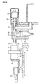
- Each filling nozzle 8 is constructed from a nozzle main body 13, an up-and-down piston 14 which ascends and descends inside this nozzle main body 13, and an air cylinder 15 which causes the up-and-down piston 14 to ascend and descend.
- a discharge port 16 is formed in the lower end of the nozzle main body 13. Furthermore, a feed-out opening 17 which communicates with the tip end (discharge opening 9a) of the corresponding cylinder 9 is formed at an intermediate position in the side wall of the nozzle main body 13, and a supply opening 18 which communicates with the tank 6 is formed at an upper position in the side wall of the nozzle main body 13.
- a discharge port opening-and-closing valve 19 is formed at the lower end of the piston 14, and a flow passage opening-and-closing valve 20 is formed at an intermediate position on the piston 14.
- the discharge port 16 is opened and closed when the discharge port opening-and-closing valve 19 is separated from or contacts a valve seat 21 formed in the lower end of the nozzle main body 13.
- the supply opening 18 and feed-out opening 17 are switched between a communicating state and a non-communicating state when the flow passage opening-and-closing valve 20 is separated from or contacts a valve seat 22 formed at an intermediate position in the nozzle main body 13.
- the upper portion of the nozzle main body 13 i.e., the upper portion of the supply opening 18
- Each of the pump devices 11 is comprised of a cylinder 9, a piston 10 a cam mechanism 24 which operates the piston 10, and other components.
- the cylinder 9 and a filling liquid flow passage 26 are formed in a cylinder block 25, and this cylinder block 25 is attached to the bottom plate 27 of the tank 6.
- the cylinder 9 is disposed in a horizontal position with the discharge opening 9a of the cylinder 9 facing outward when seen from the axial center of the filling rotor 4.
- the discharge opening 9a coincides with the feed-out opening 17. Meanwhile, one opening of the flow passage 26 coincides with the supply opening 18, while another opening of the flow passage 26 coincides with an opening formed in the bottom plate 27 of the tank.
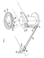
- the cam mechanism 24 comprises: a swing lever 29 which is connected to the rear end of the piston 10 via a pin 28 so that the swing lever 29 rotates horizontally; a vertical supporting shaft 32 that is, at its upper end, connected to the swing lever 29 and is shaft-supported via a supporting shaft supporting stand 31 so that the supporting shaft 32 rotatable inside the filling rotor 4; a cam lever 33 fastened at its one end to the lower end of the supporting shaft 32; a cam roller 34 which is attached to another end of the cam lever 33 so as to be rotatable in the horizontal direction; and a piston operating cam 36 equipped with an annular groove 35 so that the cam roller 34 rotatably fits in this groove 35.
- the supporting shaft supporting stand 31 is fastened to the supporting shaft holding portion (horizontal portion) 51 a of a bracket 51 that is described below.
- the piston operating cam 36 is disposed in a horizontal position on a guide plate 37 which is fastened to the supporting stand 2.
- the inward-facing guide surfaces of two guide blocks 38 that are attached to the lower portion of the piston operating cam 36 run along both side edges of the guide plate 37. Accordingly, the piston operating cam 36 is slidable only to the left and right (i.e., in the direction parallel to the guide blocks 38) on the guide plate 37.
- a nut member 41 is attached to the piston operating cam 36 via a bracket 39.
- the base portion of a screw 43 is attached to the guide plate 37 via a bracket 42 so that the screw 43 can rotate, and this screw 43 is screw-engaged with the nut member 41.
- a sprocket 44 is attached to the end portion of the screw 43, and a chain 48 is mounted on this sprocket 44 and on sprockets 45 through 47.
- the chain 48 is rotated via a gear box 59. Accordingly, the screw 43 rotates so that the piston operating cam 36 can be moved to the left or right.
- the stroke of each piston 10, i.e. the amount that is discharged each time from the cylinder 9 (the amount of liquid with which the corresponding bag is filled) can be adjusted.
- the annular groove 35 may be either substantially circular or elliptical when viewed from above.
- the shape of the annular groove 35 is selected in accordance with the discharge and suction configurations (e.g., an initially gradual discharge rate that increases at an intermediate point, etc.).
- Conveying means 12 for retainers R are installed on the outer circumference of the filling rotor 4 in positions that are beneath the filling nozzles 8 and cylinders 9.
- Retainer holding members 52 that are known in prior art, are attached to brackets 51 (on the front surface sides of the retainer holding portions (vertical portion) 51b of the brackets 51) which are attached to the outer circumference of the filling rotor 4.
- Slide rails 53 are attached in a vertical attitude to the back surfaces of the retainer holding portions 51b via slide rail attachment blocks 54.
- a retainer supporting stand 55 is installed so that the retainer supporting stand 55 is freely raised and lowered along the corresponding slide rail 53 via a slide member 56.
- a cam roller 57 is attached to the lower end of the retainer supporting stand 55, and this cam roller 57 contacts an annular raising-and-lowering cam 58 which is disposed on the bed 1.
- the retainer holding members 52 and retainer supporting stands 55 rotationally convey the retainers R. Furthermore, the cam rollers 57 run over the raising-and-lowering cam 58, so that the retainers R are raised and lowered with an appropriate timing.
- the conveying means 12 the slide rails 53, slide members 56, cam rollers 57 and raising-and-lowering cam 58, etc. constitute the "raising-and-lowering means" in the description.
- the filling nozzles 8, cylinder blocks 25 (cylinders 9 and flow passages 26 communicating with the tank) and pistons 10 are formed into units.
- those that are directly or indirectly attached to the brackets 51 are also formed into units.
- the components for the individual filling nozzle 8, except for those that are common to all of the filling nozzles 8 i.e., the piston operating cam 36, raising-and-lowering cam 58, etc.
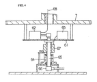
- a control section which rotates together with the filling rotor 4 is accommodated in the lower portion of the bed 1.
- This control section is comprised of: a plurality of electromagnetic valves 62 which are installed in positions that correspond to the respective air cylinders 15 on a turntable 61 which is attached to the gear 7 and rotates together with the gear 7; an AS-i (actuator sensor interface) control device 63 which is a known device and controls the operation of the electromagnetic valves 62; a hollow shaft 65 which is rotatably supported on a bearing 64 and supplies air to the respective electromagnetic valves 62; a rotary air joint 66 which is installed at the lower end of the hollow shaft 65; and a rotary feeder brush 67 which is attached to the outer circumference of the hollow shaft 65.
- Air piping 68 extends from the respective electromagnetic valves 62 to the corresponding air cylinders 15.
- Compressed air is supplied to the respective electromagnetic valves 62 from external piping system via the rotary air joint 66 and hollow shaft 65.
- Control signals and electric power that operates the respective electromagnetic valves 62 are supplied to the AS-i control device 63 from an external power supply and external control device via the rotary feeder brush 67.
- the AS-i control device 63 controls the operation of the respective electromagnetic valves 62 (switching between the pressurized side and non-pressurized side). The up and down movement of the up-and-down pistons 14 is thus controlled.
- the present invention is for a rotary type continuous filling apparatus that comprises: a tank installed on a continuously rotating filling rotor, a plurality of filling nozzles vertically disposed at equal intervals around the periphery of the filling rotor, pump devices which are disposed so as to correspond to the respective filling nozzles and in each of the pump devices a piston makes a reciprocating motion upon the rotation of the filling rotor so that a filling liquid is sucked into a cylinder from the tank and discharged toward the corresponding filling nozzle from the cylinder, and conveying means disposed beneath the respective filling nozzles in positions that correspond the filling nozzles and hold and rotationally convey containers, so that in this filling apparatus the containers are received by the conveying means, these containers are filled with the filling liquid while being rotationally conveyed, and the containers
- the cam mechanisms and the apparatus itself can be compact.
- the apparatus is superior in terms of the cleaning characteristics of its flow passages. Moreover, it provides an improved filling precision, the occurrence of accidents that involve knocking of the pistons inside the cylinders is prevented, and contamination of the openings of the bags upon filling is prevented.
Landscapes
- Engineering & Computer Science (AREA)
- Mechanical Engineering (AREA)
- Basic Packing Technique (AREA)
- Filling Of Jars Or Cans And Processes For Cleaning And Sealing Jars (AREA)
Applications Claiming Priority (2)
| Application Number | Priority Date | Filing Date | Title |
|---|---|---|---|
| JP2000096164 | 2000-03-31 | ||
| JP2000096164A JP2001278388A (ja) | 2000-03-31 | 2000-03-31 | ロータリー式連続充填装置 |
Publications (3)
| Publication Number | Publication Date |
|---|---|
| EP1145955A2 true EP1145955A2 (de) | 2001-10-17 |
| EP1145955A3 EP1145955A3 (de) | 2002-01-02 |
| EP1145955B1 EP1145955B1 (de) | 2004-05-26 |
Family
ID=18610964
Family Applications (1)
| Application Number | Title | Priority Date | Filing Date |
|---|---|---|---|
| EP01107533A Expired - Lifetime EP1145955B1 (de) | 2000-03-31 | 2001-03-27 | Kontinuerlich arbeitende Rundlauf-Abfüllmaschine |
Country Status (6)
| Country | Link |
|---|---|
| US (1) | US6378574B2 (de) |
| EP (1) | EP1145955B1 (de) |
| JP (1) | JP2001278388A (de) |
| AT (1) | ATE267737T1 (de) |
| DE (1) | DE60103446T2 (de) |
| ES (1) | ES2220614T3 (de) |
Cited By (4)
| Publication number | Priority date | Publication date | Assignee | Title |
|---|---|---|---|---|
| EP1403186A1 (de) * | 2002-09-26 | 2004-03-31 | Costruzioni Tecniche Costec S.R.L. | Drehtischfüllmaschine |
| FR2848202A1 (fr) * | 2002-12-09 | 2004-06-11 | Flextainer | Machine de remplissage d'outres ou analogues comportant un dispositif de commande a cames |
| CN100497159C (zh) * | 2006-11-28 | 2009-06-10 | 江门市江海区福田水处理设备厂 | 一种浮动式旋转灌装机 |
| CN104326098A (zh) * | 2014-09-28 | 2015-02-04 | 瑞安市胜利机械有限公司 | 一种纸塑杯灌封机的灌装机构 |
Families Citing this family (17)
| Publication number | Priority date | Publication date | Assignee | Title |
|---|---|---|---|---|
| JP4522609B2 (ja) * | 2001-04-27 | 2010-08-11 | 東洋自動機株式会社 | 包装機における包装処理装置 |
| US20030207005A1 (en) * | 2002-05-03 | 2003-11-06 | Martin John M. | Method and system for retaining high viscosity of fluid food product with the reduction of gums |
| US7319921B2 (en) * | 2002-05-22 | 2008-01-15 | Underwood Fred R | Water treatment control system |
| US6742556B1 (en) | 2002-12-19 | 2004-06-01 | Stokley-Van Camp, Inc. | Filler valve assembly |
| US7026945B2 (en) * | 2003-08-27 | 2006-04-11 | Bobby Dwyane Hill | Alarm device interface system |
| ITBO20040630A1 (it) * | 2004-10-14 | 2005-01-14 | Marchesini Group Spa | Macchina per il riempimento in continuo di contenitori con prodotti liquidi |
| CN102153036A (zh) * | 2010-12-15 | 2011-08-17 | 肇庆市京欧机械制造有限公司 | 一种广口瓶全自动回转式倒汁机 |
| JP5535155B2 (ja) * | 2011-09-05 | 2014-07-02 | 株式会社コガネイ | 流路切換弁およびそれを用いた流動性材料の吐出制御装置 |
| DE102014118094A1 (de) * | 2014-12-08 | 2016-06-09 | Krones Ag | Füllventil zum Befüllen eines zu befüllenden Behälters mit einem Füllprodukt |
| US10967303B2 (en) | 2018-03-08 | 2021-04-06 | Mark W. Romers | Filter backwash control system for a water or wastewater treatment system to conserve water during the filter backwash process |
| DE102018100353B4 (de) * | 2018-01-09 | 2020-08-06 | Khs Gmbh | Füllvorrichtung |
| CN110255474B (zh) * | 2019-07-30 | 2024-02-13 | 苏州实金食品有限公司 | 自动化灌装生产线 |
| CN114408244B (zh) * | 2022-01-25 | 2024-12-03 | 温州科迪机械有限公司 | 一种高速液体物料包装机及其充填装置 |
| CN114275208B (zh) * | 2022-01-25 | 2025-01-17 | 温州科迪机械有限公司 | 一种高速液体物料包装机及其充填装置 |
| CN114751358B (zh) * | 2022-03-30 | 2024-06-07 | 湖南泰牛高分子新材料有限公司 | 一种聚氨酯高分子涂料制备装置 |
| CN115258218B (zh) * | 2022-08-29 | 2023-05-23 | 浙江商林科技股份有限公司 | 一种用于三防漆的定量灌装设备及使用方法 |
| CN118306633B (zh) * | 2024-06-05 | 2024-08-02 | 黑龙江东方学院 | 一种乳制品包装设备 |
Citations (3)
| Publication number | Priority date | Publication date | Assignee | Title |
|---|---|---|---|---|
| JPS5942399Y2 (ja) | 1981-10-23 | 1984-12-11 | 「渋」谷工業株式会社 | 回転式定量充填装置の揺動式カム機構 |
| JPS63637Y2 (de) | 1983-09-22 | 1988-01-08 | ||
| JPH08295397A (ja) | 1995-04-21 | 1996-11-12 | Mitsubishi Heavy Ind Ltd | ロータリジョイント |
Family Cites Families (16)
| Publication number | Priority date | Publication date | Assignee | Title |
|---|---|---|---|---|
| US2185201A (en) * | 1936-05-09 | 1940-01-02 | American Can Co | Liquid filling machine |
| US3112777A (en) * | 1960-10-14 | 1963-12-03 | Fr Hesser Maschinenfabrik Ag F | Apparatus for filling bags of flexible material |
| US3195781A (en) * | 1962-10-22 | 1965-07-20 | Ex Cell O Corp | Liquid filling apparatus |
| DE1532538A1 (de) * | 1967-02-14 | 1970-03-12 | Bodo Haberkorn | Abfuellmaschine fuer fluessige und pastoese Gueter |
| DE1586082A1 (de) * | 1967-03-16 | 1970-03-26 | Habra Werk Ott Kg | Transportvorrichtung fuer quaderfoermige Beutel od.dgl. |
| US3841363A (en) * | 1971-12-30 | 1974-10-15 | Rostgo Int Corp | Container filling machine |
| US4437498A (en) * | 1981-11-09 | 1984-03-20 | Liquipak International, Inc. | Carton filling apparatus |
| JPS5942399U (ja) * | 1982-09-13 | 1984-03-19 | 三菱重工業株式会社 | 高防液堤式低温貯槽 |
| DE3443557A1 (de) * | 1984-11-29 | 1986-05-28 | Lieder Maschinenbau GmbH & Co KG, 3033 Schwarmstedt | Verfahren und vorrichtung zur abmessung eines fliessfaehigen produktes |
| NL8501983A (nl) * | 1985-07-10 | 1987-02-02 | Stork Bepak Bv | Plunjerdoseerinrichting. |
| JPS63637U (de) * | 1986-06-20 | 1988-01-06 | ||
| JPH0733638B2 (ja) * | 1989-07-05 | 1995-04-12 | 寺口産業株式会社 | 第4級アンモニウム塩を含有する繊維用抗菌防臭剤 |
| US5230373A (en) * | 1991-09-03 | 1993-07-27 | Eme Engler Usa Corp. | Piston filler |
| JPH0618881A (ja) * | 1992-07-03 | 1994-01-28 | Nec Kagoshima Ltd | 液晶表示装置 |
| JP2839828B2 (ja) * | 1993-10-08 | 1998-12-16 | 靜甲株式会社 | ロータリー式液体充填機用液体排出装置 |
| FR2760426B1 (fr) * | 1997-03-05 | 1999-04-23 | Kalix Sa | Procede de controle d'une machine de remplissage de conteneurs et machine de remplissage mettant en oeuvre le procede |
-
2000
- 2000-03-31 JP JP2000096164A patent/JP2001278388A/ja not_active Withdrawn
-
2001
- 2001-03-27 DE DE60103446T patent/DE60103446T2/de not_active Expired - Fee Related
- 2001-03-27 AT AT01107533T patent/ATE267737T1/de not_active IP Right Cessation
- 2001-03-27 EP EP01107533A patent/EP1145955B1/de not_active Expired - Lifetime
- 2001-03-27 ES ES01107533T patent/ES2220614T3/es not_active Expired - Lifetime
- 2001-03-28 US US09/819,926 patent/US6378574B2/en not_active Expired - Fee Related
Patent Citations (3)
| Publication number | Priority date | Publication date | Assignee | Title |
|---|---|---|---|---|
| JPS5942399Y2 (ja) | 1981-10-23 | 1984-12-11 | 「渋」谷工業株式会社 | 回転式定量充填装置の揺動式カム機構 |
| JPS63637Y2 (de) | 1983-09-22 | 1988-01-08 | ||
| JPH08295397A (ja) | 1995-04-21 | 1996-11-12 | Mitsubishi Heavy Ind Ltd | ロータリジョイント |
Cited By (6)
| Publication number | Priority date | Publication date | Assignee | Title |
|---|---|---|---|---|
| EP1403186A1 (de) * | 2002-09-26 | 2004-03-31 | Costruzioni Tecniche Costec S.R.L. | Drehtischfüllmaschine |
| FR2848202A1 (fr) * | 2002-12-09 | 2004-06-11 | Flextainer | Machine de remplissage d'outres ou analogues comportant un dispositif de commande a cames |
| WO2004063012A1 (fr) * | 2002-12-09 | 2004-07-29 | FLEXTAINER (Société Anonyme) | Machine de remplissage d'outres ou analogues comportant un dispositif de commande à cames |
| US6786252B2 (en) | 2002-12-09 | 2004-09-07 | Flextainer (Societe Anonyme) | Machine for filling bags or the like comprising a control device with cams |
| CN100497159C (zh) * | 2006-11-28 | 2009-06-10 | 江门市江海区福田水处理设备厂 | 一种浮动式旋转灌装机 |
| CN104326098A (zh) * | 2014-09-28 | 2015-02-04 | 瑞安市胜利机械有限公司 | 一种纸塑杯灌封机的灌装机构 |
Also Published As
| Publication number | Publication date |
|---|---|
| US20010025669A1 (en) | 2001-10-04 |
| US6378574B2 (en) | 2002-04-30 |
| ES2220614T3 (es) | 2004-12-16 |
| DE60103446D1 (de) | 2004-07-01 |
| DE60103446T2 (de) | 2005-06-23 |
| ATE267737T1 (de) | 2004-06-15 |
| JP2001278388A (ja) | 2001-10-10 |
| EP1145955B1 (de) | 2004-05-26 |
| EP1145955A3 (de) | 2002-01-02 |
Similar Documents
| Publication | Publication Date | Title |
|---|---|---|
| US6378574B2 (en) | Rotary type continuous filling apparatus | |
| EP0739828B1 (de) | Hub-Kippvorrichtung für Müllbehälter | |
| EP0575867B1 (de) | Hub-Kippvorrichtung zum Heben und Kippen eines Müllbehälters | |
| US5960838A (en) | Valve for adjustable filling chamber | |
| MX2008001930A (es) | Metodo y aparato para la limpieza automatizada de equipos de embotellado. | |
| JPH09216694A (ja) | 容器充填機における疑似ボトル、および液体を容器に充填するための回転式機械 | |
| JP2008239217A (ja) | シリンダピストン式充填装置 | |
| US6520221B2 (en) | Filling nozzle with interception of supply liquids for filling machines | |
| CA1315750C (en) | Method and apparatus for dispensing liquids | |
| JP2007238121A (ja) | 充填装置 | |
| JP3929208B2 (ja) | ロータリー式充填機のノズル洗浄装置 | |
| US5195565A (en) | Variable stroke lifter system | |
| CN2743225Y (zh) | 输液袋灌装机构 | |
| EP1213222B1 (de) | Eine Verstellvorrichtung zur Abgabe einer bestimmten Flüssigkeitsmenge in einer Abfüllanlage | |
| JP3736646B2 (ja) | ピストン式定量充填機 | |
| JPH01501136A (ja) | 充填設備における分配装置、とりわけ液体およびペースト状の製品のための充填装置とこの分配装置を操作するための方法 | |
| JP3175133B2 (ja) | 回転式充填装置の洗浄装置 | |
| JP3456502B2 (ja) | 回転式定量充填装置 | |
| US20050100433A1 (en) | Machine for orienting aligning vessels or bottles made of plastics | |
| KR100462224B1 (ko) | 액체 주입장치 | |
| EP1471032B1 (de) | Drehtischfüllmaschine mit einer pneumatischen Vorrichtung | |
| JPS6133919A (ja) | 液体充てん装置における充てんノズルの洗浄殺菌装置 | |
| US2711849A (en) | Filling apparatus for filling receptacles with grease | |
| CN222408789U (zh) | 一种灌装机夹持机构 | |
| KR20030018348A (ko) | 액정량주입장치 |
Legal Events
| Date | Code | Title | Description |
|---|---|---|---|
| PUAI | Public reference made under article 153(3) epc to a published international application that has entered the european phase |
Free format text: ORIGINAL CODE: 0009012 |
|
| AK | Designated contracting states |
Kind code of ref document: A2 Designated state(s): AT BE CH CY DE DK ES FI FR GB GR IE IT LI LU MC NL PT SE TR |
|
| AX | Request for extension of the european patent |
Free format text: AL;LT;LV;MK;RO;SI |
|
| PUAL | Search report despatched |
Free format text: ORIGINAL CODE: 0009013 |
|
| AK | Designated contracting states |
Kind code of ref document: A3 Designated state(s): AT BE CH CY DE DK ES FI FR GB GR IE IT LI LU MC NL PT SE TR |
|
| AX | Request for extension of the european patent |
Free format text: AL;LT;LV;MK;RO;SI |
|
| 17P | Request for examination filed |
Effective date: 20020702 |
|
| AKX | Designation fees paid |
Free format text: AT BE CH CY DE DK ES FI FR GB GR IE IT LI LU MC NL PT SE TR |
|
| 17Q | First examination report despatched |
Effective date: 20020930 |
|
| GRAH | Despatch of communication of intention to grant a patent |
Free format text: ORIGINAL CODE: EPIDOS IGRA |
|
| RAP1 | Party data changed (applicant data changed or rights of an application transferred) |
Owner name: TOYO JIDOKI CO., LTD. |
|
| GRAS | Grant fee paid |
Free format text: ORIGINAL CODE: EPIDOSNIGR3 |
|
| GRAA | (expected) grant |
Free format text: ORIGINAL CODE: 0009210 |
|
| AK | Designated contracting states |
Kind code of ref document: B1 Designated state(s): AT BE CH CY DE DK ES FI FR GB GR IE IT LI LU MC NL PT SE TR |
|
| PG25 | Lapsed in a contracting state [announced via postgrant information from national office to epo] |
Ref country code: TR Free format text: LAPSE BECAUSE OF FAILURE TO SUBMIT A TRANSLATION OF THE DESCRIPTION OR TO PAY THE FEE WITHIN THE PRESCRIBED TIME-LIMIT Effective date: 20040526 Ref country code: NL Free format text: LAPSE BECAUSE OF FAILURE TO SUBMIT A TRANSLATION OF THE DESCRIPTION OR TO PAY THE FEE WITHIN THE PRESCRIBED TIME-LIMIT Effective date: 20040526 Ref country code: LI Free format text: LAPSE BECAUSE OF FAILURE TO SUBMIT A TRANSLATION OF THE DESCRIPTION OR TO PAY THE FEE WITHIN THE PRESCRIBED TIME-LIMIT Effective date: 20040526 Ref country code: FI Free format text: LAPSE BECAUSE OF FAILURE TO SUBMIT A TRANSLATION OF THE DESCRIPTION OR TO PAY THE FEE WITHIN THE PRESCRIBED TIME-LIMIT Effective date: 20040526 Ref country code: CH Free format text: LAPSE BECAUSE OF FAILURE TO SUBMIT A TRANSLATION OF THE DESCRIPTION OR TO PAY THE FEE WITHIN THE PRESCRIBED TIME-LIMIT Effective date: 20040526 Ref country code: BE Free format text: LAPSE BECAUSE OF FAILURE TO SUBMIT A TRANSLATION OF THE DESCRIPTION OR TO PAY THE FEE WITHIN THE PRESCRIBED TIME-LIMIT Effective date: 20040526 Ref country code: AT Free format text: LAPSE BECAUSE OF FAILURE TO SUBMIT A TRANSLATION OF THE DESCRIPTION OR TO PAY THE FEE WITHIN THE PRESCRIBED TIME-LIMIT Effective date: 20040526 |
|
| REG | Reference to a national code |
Ref country code: GB Ref legal event code: FG4D |
|
| REG | Reference to a national code |
Ref country code: CH Ref legal event code: EP |
|
| REG | Reference to a national code |
Ref country code: IE Ref legal event code: FG4D |
|
| REF | Corresponds to: |
Ref document number: 60103446 Country of ref document: DE Date of ref document: 20040701 Kind code of ref document: P |
|
| PG25 | Lapsed in a contracting state [announced via postgrant information from national office to epo] |
Ref country code: SE Free format text: LAPSE BECAUSE OF FAILURE TO SUBMIT A TRANSLATION OF THE DESCRIPTION OR TO PAY THE FEE WITHIN THE PRESCRIBED TIME-LIMIT Effective date: 20040826 Ref country code: GR Free format text: LAPSE BECAUSE OF FAILURE TO SUBMIT A TRANSLATION OF THE DESCRIPTION OR TO PAY THE FEE WITHIN THE PRESCRIBED TIME-LIMIT Effective date: 20040826 Ref country code: DK Free format text: LAPSE BECAUSE OF FAILURE TO SUBMIT A TRANSLATION OF THE DESCRIPTION OR TO PAY THE FEE WITHIN THE PRESCRIBED TIME-LIMIT Effective date: 20040826 |
|
| REG | Reference to a national code |
Ref country code: CH Ref legal event code: PL |
|
| NLV1 | Nl: lapsed or annulled due to failure to fulfill the requirements of art. 29p and 29m of the patents act | ||
| ET | Fr: translation filed | ||
| REG | Reference to a national code |
Ref country code: ES Ref legal event code: FG2A Ref document number: 2220614 Country of ref document: ES Kind code of ref document: T3 |
|
| PGFP | Annual fee paid to national office [announced via postgrant information from national office to epo] |
Ref country code: FR Payment date: 20050324 Year of fee payment: 5 |
|
| PG25 | Lapsed in a contracting state [announced via postgrant information from national office to epo] |
Ref country code: LU Free format text: LAPSE BECAUSE OF NON-PAYMENT OF DUE FEES Effective date: 20050327 Ref country code: CY Free format text: LAPSE BECAUSE OF FAILURE TO SUBMIT A TRANSLATION OF THE DESCRIPTION OR TO PAY THE FEE WITHIN THE PRESCRIBED TIME-LIMIT Effective date: 20050327 |
|
| PG25 | Lapsed in a contracting state [announced via postgrant information from national office to epo] |
Ref country code: IE Free format text: LAPSE BECAUSE OF NON-PAYMENT OF DUE FEES Effective date: 20050328 |
|
| PGFP | Annual fee paid to national office [announced via postgrant information from national office to epo] |
Ref country code: GB Payment date: 20050329 Year of fee payment: 5 |
|
| PGFP | Annual fee paid to national office [announced via postgrant information from national office to epo] |
Ref country code: ES Payment date: 20050330 Year of fee payment: 5 |
|
| PG25 | Lapsed in a contracting state [announced via postgrant information from national office to epo] |
Ref country code: MC Free format text: LAPSE BECAUSE OF NON-PAYMENT OF DUE FEES Effective date: 20050331 |
|
| PLBE | No opposition filed within time limit |
Free format text: ORIGINAL CODE: 0009261 |
|
| STAA | Information on the status of an ep patent application or granted ep patent |
Free format text: STATUS: NO OPPOSITION FILED WITHIN TIME LIMIT |
|
| PGFP | Annual fee paid to national office [announced via postgrant information from national office to epo] |
Ref country code: DE Payment date: 20050407 Year of fee payment: 5 |
|
| 26N | No opposition filed |
Effective date: 20050301 |
|
| REG | Reference to a national code |
Ref country code: IE Ref legal event code: MM4A |
|
| PG25 | Lapsed in a contracting state [announced via postgrant information from national office to epo] |
Ref country code: GB Free format text: LAPSE BECAUSE OF NON-PAYMENT OF DUE FEES Effective date: 20060327 |
|
| PG25 | Lapsed in a contracting state [announced via postgrant information from national office to epo] |
Ref country code: ES Free format text: LAPSE BECAUSE OF NON-PAYMENT OF DUE FEES Effective date: 20060328 |
|
| PGFP | Annual fee paid to national office [announced via postgrant information from national office to epo] |
Ref country code: IT Payment date: 20060331 Year of fee payment: 6 |
|
| PG25 | Lapsed in a contracting state [announced via postgrant information from national office to epo] |
Ref country code: DE Free format text: LAPSE BECAUSE OF NON-PAYMENT OF DUE FEES Effective date: 20061003 |
|
| GBPC | Gb: european patent ceased through non-payment of renewal fee |
Effective date: 20060327 |
|
| REG | Reference to a national code |
Ref country code: FR Ref legal event code: ST Effective date: 20061130 |
|
| REG | Reference to a national code |
Ref country code: ES Ref legal event code: FD2A Effective date: 20060328 |
|
| PG25 | Lapsed in a contracting state [announced via postgrant information from national office to epo] |
Ref country code: PT Free format text: LAPSE BECAUSE OF NON-PAYMENT OF DUE FEES Effective date: 20041026 |
|
| PG25 | Lapsed in a contracting state [announced via postgrant information from national office to epo] |
Ref country code: FR Free format text: LAPSE BECAUSE OF NON-PAYMENT OF DUE FEES Effective date: 20060331 |
|
| PG25 | Lapsed in a contracting state [announced via postgrant information from national office to epo] |
Ref country code: IT Free format text: LAPSE BECAUSE OF NON-PAYMENT OF DUE FEES Effective date: 20070327 |