EP1145962B1 - Procédé et dispositif pour l'application de vignettes sur des paquets de cigarettes - Google Patents
Procédé et dispositif pour l'application de vignettes sur des paquets de cigarettes Download PDFInfo
- Publication number
- EP1145962B1 EP1145962B1 EP01830218A EP01830218A EP1145962B1 EP 1145962 B1 EP1145962 B1 EP 1145962B1 EP 01830218 A EP01830218 A EP 01830218A EP 01830218 A EP01830218 A EP 01830218A EP 1145962 B1 EP1145962 B1 EP 1145962B1
- Authority
- EP
- European Patent Office
- Prior art keywords
- packet
- corner edge
- label
- adhesive
- spot
- Prior art date
- Legal status (The legal status is an assumption and is not a legal conclusion. Google has not performed a legal analysis and makes no representation as to the accuracy of the status listed.)
- Expired - Lifetime
Links
- 235000019504 cigarettes Nutrition 0.000 title claims abstract description 14
- 238000000034 method Methods 0.000 title claims description 16
- 239000000853 adhesive Substances 0.000 claims abstract description 24
- 230000001070 adhesive effect Effects 0.000 claims abstract description 24
- 239000004831 Hot glue Substances 0.000 claims abstract description 18
- 239000011248 coating agent Substances 0.000 claims description 9
- 238000000576 coating method Methods 0.000 claims description 9
- 238000004806 packaging method and process Methods 0.000 description 5
- 239000000126 substance Substances 0.000 description 3
- 230000000694 effects Effects 0.000 description 2
- 239000000463 material Substances 0.000 description 2
- 238000011144 upstream manufacturing Methods 0.000 description 2
- 238000005452 bending Methods 0.000 description 1
- 238000004519 manufacturing process Methods 0.000 description 1
- 230000000717 retained effect Effects 0.000 description 1
Images


Classifications
-
- B—PERFORMING OPERATIONS; TRANSPORTING
- B65—CONVEYING; PACKING; STORING; HANDLING THIN OR FILAMENTARY MATERIAL
- B65C—LABELLING OR TAGGING MACHINES, APPARATUS, OR PROCESSES
- B65C9/00—Details of labelling machines or apparatus
- B65C9/20—Gluing the labels or articles
- B65C9/22—Gluing the labels or articles by wetting, e.g. by applying liquid glue or a liquid to a dry glue coating
- B65C9/2204—Gluing the labels or articles by wetting, e.g. by applying liquid glue or a liquid to a dry glue coating using spraying means
- B65C9/2208—Applying the liquid on the article
-
- B—PERFORMING OPERATIONS; TRANSPORTING
- B65—CONVEYING; PACKING; STORING; HANDLING THIN OR FILAMENTARY MATERIAL
- B65C—LABELLING OR TAGGING MACHINES, APPARATUS, OR PROCESSES
- B65C1/00—Labelling flat essentially-rigid surfaces
- B65C1/04—Affixing labels, e.g. wrap-around labels, to two or more flat surfaces of a polyhedral article
-
- B—PERFORMING OPERATIONS; TRANSPORTING
- B65—CONVEYING; PACKING; STORING; HANDLING THIN OR FILAMENTARY MATERIAL
- B65C—LABELLING OR TAGGING MACHINES, APPARATUS, OR PROCESSES
- B65C9/00—Details of labelling machines or apparatus
- B65C9/20—Gluing the labels or articles
- B65C9/22—Gluing the labels or articles by wetting, e.g. by applying liquid glue or a liquid to a dry glue coating
- B65C9/2204—Gluing the labels or articles by wetting, e.g. by applying liquid glue or a liquid to a dry glue coating using spraying means
- B65C9/2213—Applying the liquid on the label
- B65C9/2217—Applying the liquid on the label discretely, i.e. several points or strips or interrupted films
Definitions
- the present invention relates to a method and a device for the application of labels to packets of cigarettes.
- the object of the invention is to overcome the aforementioned drawback.
- the stated object is realized according to the present invention in a method of applying labels to packet of cigarettes, wherein one label is applied to each packet, straddling one corner edge, the label and the packet defining a first area of mutual contact located on the corner edge and second areas of mutual contact located on the two faces of the packet contiguous to the corner edge, the method comprising the steps of advancing the packets singly and in succession along a first predetermined path toward an affixing station, advancing the labels singly and in succession along a second predetermined path toward the affixing station and coating the second areas of mutual contact with adhesive by means of a first gumming device operating in conjunction with at least one of the first and second conveying means, in such a way that the ends of the label can be affixed to the two respective faces of the packet contiguous to the corner edge, characterized in that it also comprises the step of applying a hot melt adhesive to at least one portion of the first area of mutual contact by means of a
- the present invention relates also to a device for applying labels to packets of cigarettes.
- the aforementioned object is realized in a device according to the present invention for applying labels to packets of cigarettes, wherein one label is applied to each packet, straddling one corner edge, the label and the packet defining a first area of mutual contact located on the corner edge and second areas of mutual contact located on the two faces of the packet contiguous to the corner edge, the device comprising first conveying means by which the packets are advanced singly and in succession along a first predetermined path toward an affixing station, second conveying means by which the labels are advanced singly and in succession along a second predetermined path toward the affixing station, and a first gumming device operating in conjunction with at least one of the first and second conveying means, by which the second areas of mutual contact are coated with adhesive in such a way that the ends of the label can be affixed to the two respective faces of the packet contiguous to the corner edge, characterized in that it also comprises a second gumming device operating in conjunction with at least one of the first and second conveying means and serving to apply a hot melt
- 1 denotes a portion of a packaging machine and 2 denotes a device, in its entirety, for the application of labels 3 to packets 4 of cigarettes.
- the portion 1 of the packaging machine comprises first conveying means, denoted 5 in their entirety, by which the packets 4 are taken up singly at an infeed section 6 and advanced in succession along a first predetermined feed path P1 in a first feed direction F1 toward an affixing station 7 where a label 3, consisting for example in a manufacturing levy or revenue stamp, is applied to each packet 4.
- the device 2 comprises applicator means located at the affixing station 7 and denoted 8 in their entirety, of which the function is to attach one label 3 to each of the advancing packets 4.
- such applicator means 8 comprise a transfer unit 9 by which the labels 3 are supplied and affixed one to each packet 4; the unit 9 in question comprises a second conveyor centred on a corresponding axis 10 and appearing as a drum 11 rotatable anticlockwise in the direction denoted F2 in figure 1, so as to advance the labels 3 along a second predetermined path P2 and toward the affixing station 7, at which point the first path P1 and the second path P2 run substantially tangential.
- the drum 11 operates cantilevered from a fixed vertical bulkhead 12 presented by the portion 1 of the packaging machine, disposed with its axis 10 of rotation extending transversely to the first and second feed paths P1 and P2 and delimited radially by a substantially cylindrical wall 13 presenting a plurality of angularly equispaced means 14 by which to retain one relative label 3, each consisting in a boss 15 integral with the wall 13 and delimited radially by a surface 16 presenting a cylindrical profile concentric with the wall 13 of the drum 11.
- the drum 11 incorporates radial ducts, denoted 17 and indicated by phantom lines in figures 1 and 2, passing through each boss 15 and the relative part of the cylindrical wall 13 and terminating at the end remote from the axis 10 in respective suction holes 18 positioned to attract the labels 3.
- the holes 18 are arranged on the surface 16 of each boss 15 in rows and connected by way of the aforementioned radial ducts 17 to a pneumatic circuit not shown in the drawings, being conventional in embodiment.
- each boss 15 and by the wall 13 underneath is a radial slot 19 affording passage to a respective fold-down blade 20 capable of movement along a substantially radial trajectory relative to the drum 11 brought about by an actuating mechanism denoted 21 in its entirety, between a retracted position assumed upstream of the affixing station 7 in relation to the direction of rotation F2 of the drum 11, in which the blade 20 is located inside drum 11 as in figure 1, and an extended position assumed at the affixing station 7 in which the blade 20 projects in part from the surface 16 of the respective boss 15.
- the actuating mechanism 21 is associated with a parallelogram linkage 22 of which the function and the mechanical structure are disclosed in US Patent n° 5,111,633, to which reference may be made for a full description of the structure and operation of the components which drive the drum 11, also of the pneumatic circuit and of the actuating mechanism 21 operating the parallelogram linkage 22.
- labels 3 are released to the transfer unit 9 from a feed unit 23 mounted to the bulkhead 12 and incorporating a storage and feed line 24 along which the labels 3 advance.
- the line 24 is equipped with a magazine 25 containing a stack 26 of the labels 3, which are taken up by suction from the bottom of the selfsame stack 26 in conventional manner by a circular sector 27, and passed cyclically to the single bosses 15 of the drum 11.
- the first conveying means 5 comprise a substantially horizontal belt conveyor 28 looped around pulleys 29 (one only of which is visible in figure 1), by which packets 4 of cigarettes are caused to advance in succession along the first path P1 in the first direction F1, each lying flat and disposed with its predominating longitudinal axis extending transversely to the path P1, in contact with a horizontal surface 30 afforded by a pair of rails 31 (one only of which is visible in figure 1) each presenting a profile substantially of L shape when seen in section; the two rails 31 are spaced apart one from the other, extending parallel to the vertical bulkhead 12 and perpendicularly to the axis 10 of the drum 11.
- the packets 4 are maintained in alignment by two lateral conveyors 32 (one only of which is visible in figure 1) disposed on either side of the belt conveyor 28, at a height above a top branch of the selfsame conveyor 28, which is furnished also with a plurality of outwardly projecting and uniformly distributed pushing appendages 33 occupying the space between the two rails 31 in such a way as to engage the packets 4 and direct them toward the affixing station 7.
- the device 2 will be seen to comprise a first gumming device 34, stationed along the second path P2 beyond the magazine 25 in the direction of rotation F2 described by the drum 11, and a second gumming device 35 stationed further along the path P2.
- the first gumming device 34 comprises a reservoir 36 and a pair of coaxial rollers 37 (one only of which is visible in figure 1), disposed tangentially to the surface 16 of each boss 15 and in such a way, as discernible clearly from figure 3 in particular, as to deposit two substantially parallel dabs 38 of cold setting adhesive on the face 3a of each label 3 destined to enter into contact with the relative packet 4.
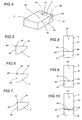
- the second gumming device 35 is a jet type and comprises a nozzle 39 designed, as discernible from figure 3, to deposit a spot 40 of hot melt adhesive between the two dabs 38 of cold setting adhesive deposited previously.
- the labels 3 are transferred to the periphery of the drum 11 from above by the circular sector 27, released cyclically onto the surfaces 16 of the bosses 15 and retained on each surface through the agency of the suction holes 18.
- Each label 3 is then transferred without pause, as the drum rotates continuously in the conveying direction F2, toward the stations occupied by the gumming devices 34 and 35.
- two elongated dabs 38 of cold setting adhesive material are applied to the outward facing surface 3a of the label 3, whereas at the gumming station occupied by the second gumming device 35, a spot 40 of hot melt adhesive is applied to this same surface 3a of the label 3 by the nozzle 39.
- Each gummed label 3 arrives thus at the affixing station 7 and is offered to a relative packet 4; more exactly, the end 41 of the label 3 positioned forwardmost along the direction of rotation F2 of the drum 11 is offered to the top face 42 of the packet 4, whilst the remaining end 43 projecting freely from the top face 42 is bent immediately and flattened against the flank face 44 of the packet 4 adjoining the top face 42. In this situation the label 3 remains tacked to one corner edge 45 of the packet 4 by the action of the spot 40 of hot melt adhesive.
- the second gumming device 35 is positioned along the first path P1 associated with the looped belt conveyor 28 rather than along the second path P2 associated with the drum 11, in such a way as to apply a spot 40 of hot melt adhesive to the corner edge 45 of the packet 4 at a given moment immediately before the packet enters the affixing station 7.
- the method disclosed envisages a first area of mutual contact denoted 46 which can be an area either of the label 3 or of the corner edge 45, to which a spot 40 of hot melt adhesive is applied, also second areas of mutual contact 47 which can be areas of the two ends 41 and 43 of the label 3 or areas of the two portions presented by the faces 42 and 44 of the packet 4 to which the two corresponding ends 41 and 43 of the label 3 are affixed by means of the dabs 38 of cold setting adhesive.
- the second gumming device 35 when stationed along the first path P1 associated with the belt conveyor 28 in a position immediately upstream of the affixing station 7, can be made to place the spot 40 of hot melt adhesive exactly on the corner edge 45 as in figure 5, or alternatively on the top face 42 or the flank face 44 of the packet 4, in either case immediately adjacent to the corner edge 45 as in figures 6 and 7 respectively.
- the second gumming device 35 can place the spot 40 of hot melt adhesive exactly on a line 45' destined to coincide with the corner edge 45 of the packet 4 as illustrated in figure 8, or on a point in close proximity to the line 45' as in figures 9 and 10.
- the function of the spot 40 of hot melt adhesive applied to the first area of mutual contact 46 is to tack the gummed label 3 in effect instantaneously to the packet 4 and prevent it thus from springing back to the former flat condition, ensuring that the correct position, straddling the corner edge 45 of the packet 4, is maintained for a length of time sufficient for the dabs 38 of cold setting adhesive to cure completely.
Landscapes
- Wrapping Of Specific Fragile Articles (AREA)
- Labeling Devices (AREA)
- Basic Packing Technique (AREA)
- Manufacturing Of Cigar And Cigarette Tobacco (AREA)
- Closing Of Containers (AREA)
Claims (17)
- Un procédé pour l'application de vignettes sur des paquets de cigarettes, où une vignette (3) est appliquée sur chaque paquet (4), à cheval sur une arête (45), la vignette (3) et le paquet (4) définissant une première zone (46) de contact réciproque située sur l'arête (45) et des secondes zones (47) de contact réciproque situées sur les deux faces (42, 44) du paquet (4) contiguës à l'arête (45), le procédé comprenant les phases consistant à faire avancer les paquets (4) un à un et en succession le long d'un premier parcours (P1) prédéterminé vers une station d'application (7), à faire avancer les vignettes (3) une à une et en succession le long d'un second parcours (P2) prédéterminé vers la station d'application (7) et à encoller les secondes zones (47) de contact réciproque par l'intermédiaire d'un premier dispositif de gommage (34) fonctionnant en association avec au moins un de premiers et seconds moyens de transport (5; 9, 11), de manière à pouvoir fixer les extrémités (41, 43) de la vignette (3) sur les deux faces (42, 44) respectives du paquet (4) contiguës à l'arête (45),
ledit procédé étant caractérisé en ce qu'il comprend aussi la phase consistant à appliquer une colle à chaud sur au moins une partie de la première zone (46) de contact réciproque par l'intermédiaire d'un second dispositif de gommage (35) fonctionnant en association avec au moins un des premiers et seconds moyens de transport (5; 9, 11), de manière à fixer la vignette (3) sur le paquet (4) au niveau de l'arête (45). - Le procédé selon la revendication 1, caractérisé en ce que la phase de fixation de la vignette (3) sur l'arête (45) comprend la phase auxiliaire consistant à interposer au moins un point (40) de colle à chaud entre la vignette (3) et l'arête (45).
- Le procédé selon la revendication 2, caractérisé en ce que la phase d'interposition consiste à appliquer le point (40) de colle à proximité de l'arête (45) du paquet (4).
- Le procédé selon la revendication 2, caractérisé en ce que la phase d'interposition prévoit d'appliquer le point (40) de colle directement sur l'arête (45) du paquet (4).
- Le procédé selon la revendication 2, caractérisé en ce que la phase d'interposition prévoit d'appliquer le point (40) de colle sur une zone (46) de la vignette (3) destinée à adhérer au paquet (4) à proximité de l'arête (45).
- Le procédé selon la revendication 2, caractérisé en ce que la phase d'interposition consiste à appliquer le point (40) de colle sur une zone (45') de la vignette (3) destinée à adhérer au paquet (4) directement sur l'arête (45).
- Le procédé selon les revendications précédentes, caractérisé en ce que la phase consistant à encoller les secondes zones (47) de contact réciproque par l'intermédiaire d'un premier dispositif de gommage (34) prévoit l'utilisation d'une colle à froid.
- Le procédé selon la revendication 7, caractérisé en ce que la phase d'encollage prévoit l'application d'au moins une couche de colle à froid sur des zones (47) respectives des deux faces (42, 44) du paquet (4) contiguës à l'arête (45), auxquelles les extrémités (41, 43) de la vignette (3) sont destinées à adhérer.
- Le procédé selon la revendication 7, caractérisé en ce que la phase d'encollage prévoit l'application d'au moins une couche de colle à froid sur des zones (47) respectives des extrémités (41, 43) de la vignette (3) destinées à adhérer aux deux faces (42, 44) du paquet (4) contiguës à l'arête (45).
- Un dispositif pour l'application de vignettes sur des paquets de cigarettes, où une vignette (3) est appliquée sur chaque paquet (4), à cheval sur une arête (45), la vignette (3) et le paquet (4) définissant une première zone (46) de contact réciproque située sur l'arête (45) et des secondes zones (47) de contact réciproque situées sur les deux faces (42, 44) du paquet (4) contiguës à l'arête (45), le dispositif (2) comprenant des premiers moyens de transport (5) destinés à faire avancer les paquets (4) un à un et en succession le long d'un premier parcours (P1) prédéterminé vers une station d'application (7), des seconds moyens de transport (9, 11) destinés à faire avancer les vignettes (3) une à une et en succession le long d'un second parcours (P2) prédéterminé vers la station d'application (7), et un premier dispositif de gommage (34) fonctionnant en association avec au moins un des premiers et seconds moyens de transport (5; 9, 11) et destiné à encoller les secondes zones (47) de contact réciproque de manière à pouvoir fixer les extrémités (41, 43) de la vignette (3) sur les deux faces (42, 44) respectives du paquet (4) contiguës à l'arête (45), ledit dispositif étant caractérisé en ce qu'il comprend aussi un second dispositif de gommage (35) fonctionnant en association avec au moins un des premiers et seconds moyens de transport (5; 9, 11) et servant à appliquer une colle à chaud sur au moins une partie de la première zone (46) de contact réciproque de manière à fixer la vignette (3) sur le paquet (4) au niveau de l'arête (45).
- Le dispositif selon la revendication 10, caractérisé en ce que le second dispositif de gommage (35) est positionné le long du premier parcours (P1) prédéterminé de manière à déposer un point (40) de colle à chaud à proximité de l'arête (45) du paquet (4).
- Le dispositif selon la revendication 10, caractérisé en ce que le second dispositif de gommage (35) est positionné le long du premier parcours (P1) prédéterminé de manière à déposer un point (40) de colle à chaud directement sur l'arête (45) du paquet (4).
- Le dispositif selon la revendication 10, caractérisé en ce que le second dispositif de gommage (35) est positionné le long du second parcours (P2) prédéterminé de manière à déposer un point (40) de colle à chaud sur une zone (46) de la vignette (3) destinée à adhérer au paquet (4) en un point situé à proximité de l'arête (45).
- Le dispositif selon la revendication 10, caractérisé en ce que le second dispositif de gommage (35) est positionné le long du second parcours (P2) prédéterminé de manière à déposer un point (40) de colle à chaud sur une zone (45') de la vignette (3) destinée à adhérer au paquet (4) en un point situé directement sur l'arête (45).
- Le dispositif selon la revendication 10, caractérisé en ce que le premier dispositif de gommage (34) fonctionne en association avec les premiers moyens de transport (5) de manière à appliquer au moins une couche (38) de colle à froid sur les deux faces (42, 44) du paquet (4) contiguës à l'arête (45) afin de fixer les extrémités (41, 43) de la vignette (3).
- Le dispositif selon la revendication 10, caractérisé en ce que le premier dispositif de gommage (34) fonctionne en association avec les seconds moyens de transport (9, 11) de manière à appliquer au moins une couche (38) de colle à froid sur les extrémités (41, 43) de la vignette (3) destinées à adhérer aux deux faces (42, 44) du paquet (4) contiguës à l'arête (45) afin de fixer les extrémités (41, 43) elles-mêmes de la vignette (3).
- Un paquet de cigarettes avec une vignette appliquée à cheval sur une arête, obtenu par le procédé selon les revendications de 1 à 9.
Applications Claiming Priority (2)
| Application Number | Priority Date | Filing Date | Title |
|---|---|---|---|
| IT2000BO000210A IT1320985B1 (it) | 2000-04-10 | 2000-04-10 | Metodo e dispositivo per l'applicazione di fascette a pacchetti disigarette. |
| ITBO000210 | 2000-04-10 |
Publications (2)
| Publication Number | Publication Date |
|---|---|
| EP1145962A1 EP1145962A1 (fr) | 2001-10-17 |
| EP1145962B1 true EP1145962B1 (fr) | 2006-07-19 |
Family
ID=11438404
Family Applications (1)
| Application Number | Title | Priority Date | Filing Date |
|---|---|---|---|
| EP01830218A Expired - Lifetime EP1145962B1 (fr) | 2000-04-10 | 2001-03-29 | Procédé et dispositif pour l'application de vignettes sur des paquets de cigarettes |
Country Status (5)
| Country | Link |
|---|---|
| EP (1) | EP1145962B1 (fr) |
| AT (1) | ATE333415T1 (fr) |
| DE (1) | DE60121492T2 (fr) |
| IT (1) | IT1320985B1 (fr) |
| RU (1) | RU2257316C2 (fr) |
Families Citing this family (5)
| Publication number | Priority date | Publication date | Assignee | Title |
|---|---|---|---|---|
| NL1026731C2 (nl) * | 2004-07-27 | 2006-01-30 | William Van Der Burg | Werkwijze en inrichting voor het op een bloempot aanbrengen van een etiket alsmede zo verkregen bloempot. |
| EP2712819B1 (fr) * | 2012-09-28 | 2016-02-24 | Kronoplus Technical AG | Appareil et procédé pour appliquer des étiquettes sur des boîtes |
| CN109229689B (zh) * | 2018-08-27 | 2020-08-18 | 浙江信基科技有限公司 | 一种汽车零部件用贴标机 |
| CN109911357A (zh) * | 2019-03-21 | 2019-06-21 | 南昌科悦企业管理咨询有限公司 | 一种蓝牙耳机包装用的标签粘贴设备 |
| FI131867B1 (en) | 2021-02-04 | 2026-01-16 | Intelligent Fridges Bv | Procedure for tagging products and a product |
Family Cites Families (4)
| Publication number | Priority date | Publication date | Assignee | Title |
|---|---|---|---|---|
| DE2901825A1 (de) * | 1979-01-18 | 1980-07-31 | Hauni Werke Koerber & Co Kg | Vorrichtung zum aufbringen eines etikettes auf packungen der tabakverarbeitenden industrie |
| IT1235977B (it) * | 1989-12-18 | 1992-12-15 | Gd Spa | Dispositivo per l'applicazione di fascette a pacchetti sostanzialmenteparallelepipedi |
| DE19647670A1 (de) * | 1996-11-19 | 1998-05-20 | Focke & Co | Verfahren und Vorrichtung zum Herstellen von Banderolen und Anbringen an (Zigaretten-)Packungen |
| RU2109664C1 (ru) * | 1997-02-14 | 1998-04-27 | Общество с ограниченной ответственностью Инженерно-технический центр "Контакт ЛТД" | Аппарат для этикетирования или прикрепления тонких листовых изделий к плоским поверхностям прямоугольных упаковок |
-
2000
- 2000-04-10 IT IT2000BO000210A patent/IT1320985B1/it active
-
2001
- 2001-03-29 EP EP01830218A patent/EP1145962B1/fr not_active Expired - Lifetime
- 2001-03-29 DE DE60121492T patent/DE60121492T2/de not_active Expired - Fee Related
- 2001-03-29 AT AT01830218T patent/ATE333415T1/de not_active IP Right Cessation
- 2001-04-09 RU RU2001109599/12A patent/RU2257316C2/ru not_active IP Right Cessation
Also Published As
| Publication number | Publication date |
|---|---|
| RU2257316C2 (ru) | 2005-07-27 |
| ITBO20000210A1 (it) | 2001-10-10 |
| DE60121492T2 (de) | 2007-02-22 |
| EP1145962A1 (fr) | 2001-10-17 |
| IT1320985B1 (it) | 2003-12-18 |
| ATE333415T1 (de) | 2006-08-15 |
| DE60121492D1 (de) | 2006-08-31 |
Similar Documents
| Publication | Publication Date | Title |
|---|---|---|
| US4473429A (en) | High speed wrap around label applicator and method | |
| EP0944528B1 (fr) | Appareil d'etiquetage en rouleau | |
| US4605459A (en) | Literature applying machine and method | |
| AU618353B2 (en) | Straight through labelling machine | |
| EP0865987B1 (fr) | Procédé de pliage pour la formation d'une enveloppe tubulaire scellée | |
| JPS63152531A (ja) | 容器ラベル貼着方法 | |
| CA2074921C (fr) | Systeme d'etiquetage de corps cylindriques avec dispositifs de chauffage retractables commandes par cames et a longueur de parcours reglable | |
| JP4060419B2 (ja) | (印刷した)帯封ラベルとこれを(煙草)パケットに付与する方法と装置 | |
| EP0956239B1 (fr) | Dispositif et procede d'application de coupons detachables sur des paquets sensiblement parallelepipediques | |
| EP0455377B1 (fr) | Procédé et machine d'étiquetage | |
| US4602977A (en) | Combination labeling and literature applying machine | |
| US4647333A (en) | Combination labeling and literature applying machine | |
| CN101269710A (zh) | 用于将标签贴到包装上的设备和方法 | |
| US20060076111A1 (en) | Method and unit for applying a label to an article | |
| EP0654409B1 (fr) | Dispositif pour l'application d'étiquettes de fermeture sur des paquets | |
| EP1145962A1 (fr) | Procédé et dispositif pour l'application de vignettes sur des paquets de cigarettes | |
| EP1186538B1 (fr) | Procédé et appareil d'étiquetage | |
| JPH021210Y2 (fr) | ||
| JP3036724B2 (ja) | ラベリング装置 | |
| EP1712476B1 (fr) | Procédé et dispositif pour appliquer des étiquettes sur des produits | |
| GB2188608A (en) | Combination labelling and literature applying machine | |
| JP2529116B2 (ja) | フイルタ取付け機 | |
| EP0662423B1 (fr) | Dispositif pour appliquer des étiquettes de scellage sur des réceptacles | |
| US4331498A (en) | Method of and apparatus for wrapping tops of bottles with foil | |
| JP2023552617A (ja) | ラベル貼付装置 |
Legal Events
| Date | Code | Title | Description |
|---|---|---|---|
| PUAI | Public reference made under article 153(3) epc to a published international application that has entered the european phase |
Free format text: ORIGINAL CODE: 0009012 |
|
| AK | Designated contracting states |
Kind code of ref document: A1 Designated state(s): AT BE CH CY DE DK ES FI FR GB GR IE IT LI LU MC NL PT SE TR |
|
| AX | Request for extension of the european patent |
Free format text: AL;LT;LV;MK;RO;SI |
|
| 17P | Request for examination filed |
Effective date: 20020121 |
|
| AKX | Designation fees paid |
Free format text: AT BE CH CY DE DK ES FI FR GB GR IE IT LI LU MC NL PT SE TR |
|
| GRAP | Despatch of communication of intention to grant a patent |
Free format text: ORIGINAL CODE: EPIDOSNIGR1 |
|
| GRAS | Grant fee paid |
Free format text: ORIGINAL CODE: EPIDOSNIGR3 |
|
| GRAA | (expected) grant |
Free format text: ORIGINAL CODE: 0009210 |
|
| RAP1 | Party data changed (applicant data changed or rights of an application transferred) |
Owner name: G.D S.P.A. |
|
| AK | Designated contracting states |
Kind code of ref document: B1 Designated state(s): AT BE CH CY DE DK ES FI FR GB GR IE IT LI LU MC NL PT SE TR |
|
| PG25 | Lapsed in a contracting state [announced via postgrant information from national office to epo] |
Ref country code: AT Free format text: LAPSE BECAUSE OF FAILURE TO SUBMIT A TRANSLATION OF THE DESCRIPTION OR TO PAY THE FEE WITHIN THE PRESCRIBED TIME-LIMIT Effective date: 20060719 Ref country code: FI Free format text: LAPSE BECAUSE OF FAILURE TO SUBMIT A TRANSLATION OF THE DESCRIPTION OR TO PAY THE FEE WITHIN THE PRESCRIBED TIME-LIMIT Effective date: 20060719 Ref country code: BE Free format text: LAPSE BECAUSE OF FAILURE TO SUBMIT A TRANSLATION OF THE DESCRIPTION OR TO PAY THE FEE WITHIN THE PRESCRIBED TIME-LIMIT Effective date: 20060719 Ref country code: NL Free format text: LAPSE BECAUSE OF FAILURE TO SUBMIT A TRANSLATION OF THE DESCRIPTION OR TO PAY THE FEE WITHIN THE PRESCRIBED TIME-LIMIT Effective date: 20060719 Ref country code: IT Free format text: LAPSE BECAUSE OF FAILURE TO SUBMIT A TRANSLATION OF THE DESCRIPTION OR TO PAY THE FEE WITHIN THE PRESCRIBED TIME-LIMIT;WARNING: LAPSES OF ITALIAN PATENTS WITH EFFECTIVE DATE BEFORE 2007 MAY HAVE OCCURRED AT ANY TIME BEFORE 2007. THE CORRECT EFFECTIVE DATE MAY BE DIFFERENT FROM THE ONE RECORDED. Effective date: 20060719 |
|
| REG | Reference to a national code |
Ref country code: GB Ref legal event code: FG4D |
|
| REG | Reference to a national code |
Ref country code: CH Ref legal event code: EP |
|
| REG | Reference to a national code |
Ref country code: IE Ref legal event code: FG4D |
|
| REF | Corresponds to: |
Ref document number: 60121492 Country of ref document: DE Date of ref document: 20060831 Kind code of ref document: P |
|
| PG25 | Lapsed in a contracting state [announced via postgrant information from national office to epo] |
Ref country code: SE Free format text: LAPSE BECAUSE OF FAILURE TO SUBMIT A TRANSLATION OF THE DESCRIPTION OR TO PAY THE FEE WITHIN THE PRESCRIBED TIME-LIMIT Effective date: 20061019 Ref country code: DK Free format text: LAPSE BECAUSE OF FAILURE TO SUBMIT A TRANSLATION OF THE DESCRIPTION OR TO PAY THE FEE WITHIN THE PRESCRIBED TIME-LIMIT Effective date: 20061019 |
|
| PG25 | Lapsed in a contracting state [announced via postgrant information from national office to epo] |
Ref country code: ES Free format text: LAPSE BECAUSE OF FAILURE TO SUBMIT A TRANSLATION OF THE DESCRIPTION OR TO PAY THE FEE WITHIN THE PRESCRIBED TIME-LIMIT Effective date: 20061030 |
|
| REG | Reference to a national code |
Ref country code: CH Ref legal event code: NV Representative=s name: BUGNION S.A. |
|
| NLV1 | Nl: lapsed or annulled due to failure to fulfill the requirements of art. 29p and 29m of the patents act | ||
| ET | Fr: translation filed | ||
| PGFP | Annual fee paid to national office [announced via postgrant information from national office to epo] |
Ref country code: GB Payment date: 20070327 Year of fee payment: 7 |
|
| PGFP | Annual fee paid to national office [announced via postgrant information from national office to epo] |
Ref country code: CH Payment date: 20070328 Year of fee payment: 7 |
|
| PGFP | Annual fee paid to national office [announced via postgrant information from national office to epo] |
Ref country code: DE Payment date: 20070430 Year of fee payment: 7 |
|
| PLBE | No opposition filed within time limit |
Free format text: ORIGINAL CODE: 0009261 |
|
| STAA | Information on the status of an ep patent application or granted ep patent |
Free format text: STATUS: NO OPPOSITION FILED WITHIN TIME LIMIT |
|
| 26N | No opposition filed |
Effective date: 20070420 |
|
| PG25 | Lapsed in a contracting state [announced via postgrant information from national office to epo] |
Ref country code: MC Free format text: LAPSE BECAUSE OF NON-PAYMENT OF DUE FEES Effective date: 20070331 Ref country code: IE Free format text: LAPSE BECAUSE OF NON-PAYMENT OF DUE FEES Effective date: 20070329 |
|
| PG25 | Lapsed in a contracting state [announced via postgrant information from national office to epo] |
Ref country code: GR Free format text: LAPSE BECAUSE OF FAILURE TO SUBMIT A TRANSLATION OF THE DESCRIPTION OR TO PAY THE FEE WITHIN THE PRESCRIBED TIME-LIMIT Effective date: 20061020 |
|
| PGFP | Annual fee paid to national office [announced via postgrant information from national office to epo] |
Ref country code: FR Payment date: 20070319 Year of fee payment: 7 |
|
| REG | Reference to a national code |
Ref country code: CH Ref legal event code: PL |
|
| GBPC | Gb: european patent ceased through non-payment of renewal fee |
Effective date: 20080329 |
|
| REG | Reference to a national code |
Ref country code: FR Ref legal event code: ST Effective date: 20081125 |
|
| PG25 | Lapsed in a contracting state [announced via postgrant information from national office to epo] |
Ref country code: DE Free format text: LAPSE BECAUSE OF NON-PAYMENT OF DUE FEES Effective date: 20081001 Ref country code: LI Free format text: LAPSE BECAUSE OF NON-PAYMENT OF DUE FEES Effective date: 20080331 Ref country code: CH Free format text: LAPSE BECAUSE OF NON-PAYMENT OF DUE FEES Effective date: 20080331 |
|
| PG25 | Lapsed in a contracting state [announced via postgrant information from national office to epo] |
Ref country code: FR Free format text: LAPSE BECAUSE OF NON-PAYMENT OF DUE FEES Effective date: 20080331 |
|
| PG25 | Lapsed in a contracting state [announced via postgrant information from national office to epo] |
Ref country code: GB Free format text: LAPSE BECAUSE OF NON-PAYMENT OF DUE FEES Effective date: 20080329 |
|
| PG25 | Lapsed in a contracting state [announced via postgrant information from national office to epo] |
Ref country code: CY Free format text: LAPSE BECAUSE OF FAILURE TO SUBMIT A TRANSLATION OF THE DESCRIPTION OR TO PAY THE FEE WITHIN THE PRESCRIBED TIME-LIMIT Effective date: 20060719 Ref country code: LU Free format text: LAPSE BECAUSE OF NON-PAYMENT OF DUE FEES Effective date: 20070329 |
|
| PG25 | Lapsed in a contracting state [announced via postgrant information from national office to epo] |
Ref country code: TR Free format text: LAPSE BECAUSE OF FAILURE TO SUBMIT A TRANSLATION OF THE DESCRIPTION OR TO PAY THE FEE WITHIN THE PRESCRIBED TIME-LIMIT Effective date: 20060719 |
|
| PG25 | Lapsed in a contracting state [announced via postgrant information from national office to epo] |
Ref country code: PT Free format text: LAPSE BECAUSE OF FAILURE TO SUBMIT A TRANSLATION OF THE DESCRIPTION OR TO PAY THE FEE WITHIN THE PRESCRIBED TIME-LIMIT Effective date: 20060719 |