EP1146006B1 - Warntafel für Biegarmkräne - Google Patents
Warntafel für Biegarmkräne Download PDFInfo
- Publication number
- EP1146006B1 EP1146006B1 EP01850057A EP01850057A EP1146006B1 EP 1146006 B1 EP1146006 B1 EP 1146006B1 EP 01850057 A EP01850057 A EP 01850057A EP 01850057 A EP01850057 A EP 01850057A EP 1146006 B1 EP1146006 B1 EP 1146006B1
- Authority
- EP
- European Patent Office
- Prior art keywords
- lamps
- cylinder
- pressure
- display panel
- lamp
- Prior art date
- Legal status (The legal status is an assumption and is not a legal conclusion. Google has not performed a legal analysis and makes no representation as to the accuracy of the status listed.)
- Expired - Lifetime
Links
Images


Classifications
-
- B—PERFORMING OPERATIONS; TRANSPORTING
- B66—HOISTING; LIFTING; HAULING
- B66C—CRANES; LOAD-ENGAGING ELEMENTS OR DEVICES FOR CRANES, CAPSTANS, WINCHES, OR TACKLES
- B66C23/00—Cranes comprising essentially a beam, boom, or triangular structure acting as a cantilever and mounted for translatory of swinging movements in vertical or horizontal planes or a combination of such movements, e.g. jib-cranes, derricks, tower cranes
- B66C23/88—Safety gear
- B66C23/90—Devices for indicating or limiting lifting moment
- B66C23/905—Devices for indicating or limiting lifting moment electrical
Definitions
- This invention relates to a warning sign for bending arm cranes two or more by hydraulic cylinders pivotable arms, which has two rows of lamps, with at least one with the individual cylinder cooperating pressure transducer are connected in dependence on prevailing in the cylinder hydraulic fluid pressure turned on or turned off, in the way that a first lamp is turned on in each row, when the pressure is low, after which gradually more and more lamps be turned on in the series when the pressure against a maximum permissible pressure increases, and the lamps are reversed in succession switched off when the pressure drops, the panel means for Display of violations of said maximum pressure.
- Cranes for both lifting and other work tasks include, beside one Crane foot and a pillar, at least two hinged arms, namely a hinged to the pillar lifting arm and a with the Lift arm articulated connected swing arm.
- Each of these arms is movable by means of an associated hydraulic cylinder, namely, the lifting and swinging arms by means of a lifting cylinder or a swing cylinder pivotally movable. All cylinders are connected to a common hydraulic system, which often makes sense Equipment for the operation of the crane, connected.
- the crane can be quickly broken off by hand as needed may belong to this equipment.
- a so-called belongs Overload protection which has the functions of the task Break off crane when the hydraulic fluid pressure in one of the cylinder reaches a maximum allowable working pressure, too the equipment.
- An already known warning sign includes a triangular shaped Set of lamps in the form of light-emitting diodes, on the one hand blink when the hydra-pressure in one of the cylinders of the crane is 90% reached the maximum allowable pressure (100%), on the other hand with a solid glow when the overload protection is activated and the crane stops, ie when the hydrautruck reaches 100%.
- this warning panel provides no indication at all Which cylinder limits the lifting power, and also no information about in which only one cylinder or possibly several cylinders the have reached the maximum allowable pressure.
- Warning sign comprises two sets of light-emitting diodes, of which one of the pressure load in percent for the most heavily loaded Hydraulic cylinder indicates while the other indicates which cylinder meant is.
- this table provides only information about the am highest loaded hydraulic cylinder, while information on the rest Cylinders completely missing.
- the present invention has the object the above-mentioned disadvantages to eliminate the already known warning sign for cranes and improved Warning sign to create.
- a basic object of the invention is thus a warning sign, which gives the surgeon requirements in a thoughtfully simple way to perceive timely to what extent one or more sturgeon commando on the way is to one Trigger the overload protection, to create.
- Words has the warning sign at any moment during crane operation To explain to the surgeon, how far an immediate danger an interruption of service exists without the condition that the Surgeon to engage in a complicated and time-consuming thought activity Has. All of this has the purpose of unnecessary business interruptions to avoid.
- a warning sign of the type mentioned above is disclosed by EP 0 236 804 already known.
- this well-known warning sign belong at all no cylinder symbols and even less a silhouetted one Crane symbol indicating to the eye and thought directly to which Cylinder belong to the respective lamp rows.
- the normal load condition or overload condition with the help of special Lamps are displayed which are separate from the pressure-indicating ones Lamp rows are placed.
- the warning board includes not more than one row of lamps, which also has one placed separately on the board mounted crane symbol.
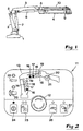
- FIG. 1 shows the most important parts of a conventional Crane of the bending arm style illustrated.
- this crane comprises two Arms, namely a lifting arm 3 and a swing arm 4.
- the lifting arm. 3 is connected by a first joint 5 with the pillar 2, while a second joint 6 connects the swing arm 4 with the lifting arm 3.
- the Arms 3, 4 are thus by the joints 5, 6 pivotally.
- the crane points two hydraulic cylinders in order to obtain necessary pivoting movements, namely a lifting cylinder 7 for operating the lifting arm 3, and a swing cylinder 8 for operating the swing arm 4.
- Swing arm 4 can advantageously - although not necessarily -
- All cylinders are parts of a common hydraulic system, a so-called Overload protection, which includes the application of at least a pressure transducer for each hydraulic cylinder (not shown) based is, which continuously information about the in the respective hydraulic cylinder prevailing pressure to a central control unit (not shown) supplies.
- a warning sign is connected to this control unit, and this will be described below.
- the panel 11 shown in Figure 2 has the shape of a rectangular disc, which in fact as an externally visible end wall of a shell which includes a number of electrical components for u a a number houses of lamps of the table.
- a Hole for an emergency stop button 12 available, with the help of the operation The crane can be completely stopped by hand as needed can.
- the board has a stylized, silhouetted crane symbol, which generally designated 13 and in the present case two Cylinder symbols 14, 15 comprising, which with a set of lamps cooperate and that are shown in the preferred embodiment the invention four lamps in connection to each one Cylinder symbol provided, namely a first lamp 16, which turned on as soon as the hydraulic cylinder to be relatively moderate partial pressure works, e.g. 50%; a second Lamp 17, which is switched on as soon as the working pressure is higher, although still at a moderate level, e.g. 70%; a third Lamp 18 turned on when the working pressure a little lower than the maximum allowable pressure, e.g. 90% of the latter Pressure, as well as a fourth lamp 19, which is turned on when the maximum allowable pressure (100%) is reached. Conversely, the Lamps turned off one after the other when the prevailing working pressure falls below the stated pressure levels.
- a first lamp 16 which turned on as soon as the hydraulic cylinder to be relatively moderate partial pressure works, e.g. 50%
- a second Lamp 17 which is switched on as soon
- the lamps 16-19 are in the cylinder symbol 14 and 15 respectively, d h between the two parallel lines which form the cylinder silhouette, the lamp 16, which is the lowest Pressure level indicates, at the bottom or innermost in the respective cylinder symbol is placed, and the lamp 19, which is the highest pressure level (100%), is placed on top or placed.
- light-emitting diodes are preferred. At least some of These LEDs, namely the diodes 16, 17, are advantageously of the kind that can shine with different colors, e.g. green or red, where the color of the light of how one or more diodes other diodes light up or have not been made dependent.
- Farther may advantageously have one or more diodes with either one fixed or flashing bill depending on how one or more other lamps are lit or not working.
- the first two light emitting diodes 16, 17 thus be designed so that they on the one hand with green or red glow, on the other hand shine with firm or blinking glow can.
- the third light-emitting diode 18 can be designed such that it lights up with red glow, which is either solid or flashing.
- the fourth light-emitting diode 19 can be lit with only one fixed, be provided red glow.
- the crane symbol 13 on the warning sign also includes a fifth Lamp or light emitting diode 20 in a circular wind symbol 21 is located.
- This LED can be flashing red work when the Hydraultik in a belonging to a crane Winch (not shown) reaches 90% of maximum allowable pressure, and with a solid, red glow when reaching the maximum pressure (100%) becomes.
- the warning panel 11 a number of symbols and associated light emitting diodes on.
- a light-emitting diode is thus connected to a tool symbol 22 provided. These inform the surgeon about the Need maintenance when the LED lights up.
- the symbol 23 gives the information to what extent a vehicle-borne crane is within the permissible stability sector, depending on how much a cooperating LED is turned on or not.
- a symbol 24 cooperates with a light emitting diode to indicate in what way the crane is off or ready to start.
- the blackboard can also additional function icons and related ones Have light-emitting diodes, as indicated at 25, 26 and 27.
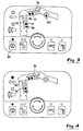
- FIGs. 2-7 A number of examples of different operating or functional states of the crane are shown in Figs. 2-7.
- the luminous LED (indicated by the field marked in black) shows in Connection to the symbol 24 in Figure 2, that the crane is in operation.
- the LED 16 of the cylinder symbol 14 is switched on and lights up with a solid, green glow to indicate that the lifting cylinder 7 of the Cranes with at least 50% hydro pressure work, d h far below the maximum permissible working pressure.
- the light emitting diodes 16, 17 in the cylinder symbol 15 glow with firm, green glow and indicate that the oscillating cylinder 8 operates at 70% pressure or more.
- the warning board according to FIG 2 the operator information, the say that the crane works normally without any immediate danger Triggered by the overload protection of the hydraulic system stopped to become.
- the two LEDs 16, 17 in each of the cylinder symbols 14, 15th are turned on in Figure 3 and shine with a firm, green glow.
- the light-emitting diode 20 is activated and flashes with red glow, indicating that the hydraultik of the winds at least 90% of the maximum allowable pressure. In this way it will be the Surgeon allows to take the necessary measures are to prevent the working pressure of the winch from reaching the maximum permissible pressure reached.
- the operating state according to FIG. 4 differs from the state 3 only by the fact that the wind pressure is normal and that the LED following the tool icon 22 indicates that the crane requires maintenance.
- the pressure in the oscillating cylinder 8 has reached the maximum allowable working pressure, ie h 100%, with all four LEDs 16, 17, 18, 19 of the cylinder symbol 15 with solid, red glow.
- the overload protection triggered and stopped the crane, but since all LEDs 16-19 have been activated in the cylinder symbol 15 are, the surgeon receives the information that just the oscillating cylinder 8 reached 100% pressure and triggered the overload protection. In other words, the surgeon can quickly find other sources of Exclude interruption and the necessary measures with regard to just grab the swing arm and its cylinder.
- the surgeon is capable of a clear and easy to understand Way without delay the individually prevailing pressure state in each of the two hydraulic cylinders 7, 8 determine what normally for triggering or not overload protection of the Hydraulics is the deciding factor. In other words, the surgeon receives good opportunities to operate the crane in such a way that eliminates the danger of unnecessary interruptions or vigorous is reduced.
- the invention is not limited to that described above and to the Drawings shown embodiment limited.
- the Number of LEDs or lamps in each cylinder symbol from just four, both up and down differ. It is desirable in itself the number of lamps in each Symbol, e.g. up to 5 to 8 if the physical place Possibility to do so on the blackboard. With an increased number of lamps in each cylinder symbol, the resolution of the obtained printing information improved.
Landscapes
- Engineering & Computer Science (AREA)
- Mechanical Engineering (AREA)
- Jib Cranes (AREA)
- Forklifts And Lifting Vehicles (AREA)
- Rear-View Mirror Devices That Are Mounted On The Exterior Of The Vehicle (AREA)
- Component Parts Of Construction Machinery (AREA)
Description
Claims (5)
- Warntafel für Biegarmkräne mit zwei oder mehr, mittels Hydraulzylinder (7, 8) schwenkbaren Armen (3, 4), welche zwei Reihen von Lampen (16, 17, 18, 19) aufweist, die mit mindestens einem mit dem einzelnen Zylinder (7, 8) zusammenwirkenden Druckgeber verbunden sind, um in Abhängigkeit des in dem Zylinder herrschenden Hydraulflüssigkeitsdruckes angeschaltet bzw ausgeschaltet zu werden, und zwar in der Weise, dass eine erste Lampe (16) in jeder Reihe angeschaltet wird, wenn der Druck niedrig ist, wonach allmählich mehr und mehr Lampen in der Reihe angeschaltet werden, wenn der Druck gegen einen maximal zulässigen Druck ansteigt, und die Lampen werden umgekehrt nacheinander ausgeschaltet, wenn der Druck sinkt, wobei die Tafel Mittel zum Anzeigen von Überschreitungen des genannten Maximaldruckes aufweist, dadurch gekennzeichnet, dass auf der Tafel (11) ein stilisiertes, silhouettenartiges Kransymbol (13) vorgesehen ist, zu welchem zwei im Winkel zueinander gerichtete Zylindersymbole (14, 15) gehören, von welchen das eine einen Hubzylinder (7) und das andere einen Schwingzylinder (8) symbolisiert, wobei die genannten Lampenreihen im Anschluss an die Zylindersymbole plaziert sind, d h im Winkel zueinander, um unmittelbar für das blosse Auge die Funktionen des Hubzylinders und des Schwingzylinders gedankenmässig zu unterscheiden, und dass das genannte Mittel für Anzeigen einer Maximaldrucksüberschreitung in jeder einzelnen Lampenreihe vorgesehen ist, nämlich dadurch, dass mindestens eine Lampe (16, 17) derart gestaltet ist, dass sie auf verschiedene Weise leuchtet in Abhängigkeit inwiefern eine oder mehrere andere Lampen in derselben Reihe angeschaltet sind oder nicht.
- Warntafel nach Anspruch 1, dadurch gekennzeichnet, dass mindestens eine Lampe (16, 17) derart ausgebildet ist, dass sie in Abhängigkeit von der Tat inwiefern eine oder mehrere andere Lampen (18, 19) angeschaltet sind oder nicht in verschiedenen Farben aufleuchtet.
- Warntafel nach Anspruch 1 oder 2, dadurch gekennzeichnet, dass mindestens eine Lampe (18) derart ausgebildet ist, dass sie in Abhängigkeit von inwiefern eine oder mehrere andere Lampe (19) angeschaltet sind oder nicht mit einem festen oder blinkenden Schein leuchtet.
- Warntafel nach einem der vorhergehenden Ansprüche, dadurch gekennzeichnet, dass die einzelne Lampenreihe (16, 17, 18, 19) zwischen zwei parallelen Linien, die ein Zylindersymbol bilden, plaziert ist.
- Warntafel nach einem der vorhergehenden Ansprüche, dadurch gekennzeichnet, dass die Lampe (16), die das niedrigste Druckniveau in einem Hubzylinder (7) anzeigt, zuunterst in der Lampenreihe, die mit dem Symbol (14) für den Hubzylinder (7) verbunden ist, gelegen ist, und dass die Lampe (16), die das niedrigste Druckniveau in einem Schwingzylinder (8) anzeigt, zuinnerst in der Lampenreihe, die mit dem Symbol (15) für den Schwingzylinder (8) verbunden ist, gelegen ist.
Applications Claiming Priority (2)
| Application Number | Priority Date | Filing Date | Title |
|---|---|---|---|
| SE0001344A SE521390C2 (sv) | 2000-04-12 | 2000-04-12 | Varningspanel för kranar |
| SE0001344 | 2000-04-12 |
Publications (3)
| Publication Number | Publication Date |
|---|---|
| EP1146006A2 EP1146006A2 (de) | 2001-10-17 |
| EP1146006A3 EP1146006A3 (de) | 2003-03-05 |
| EP1146006B1 true EP1146006B1 (de) | 2005-05-11 |
Family
ID=20279280
Family Applications (1)
| Application Number | Title | Priority Date | Filing Date |
|---|---|---|---|
| EP01850057A Expired - Lifetime EP1146006B1 (de) | 2000-04-12 | 2001-03-29 | Warntafel für Biegarmkräne |
Country Status (5)
| Country | Link |
|---|---|
| EP (1) | EP1146006B1 (de) |
| AT (1) | ATE295331T1 (de) |
| DE (1) | DE50106165D1 (de) |
| ES (1) | ES2240390T3 (de) |
| SE (1) | SE521390C2 (de) |
Families Citing this family (1)
| Publication number | Priority date | Publication date | Assignee | Title |
|---|---|---|---|---|
| CN111986448A (zh) * | 2020-08-14 | 2020-11-24 | 中联重科股份有限公司 | 臂架操作安全指示系统、方法、存储介质及处理器 |
Family Cites Families (5)
| Publication number | Priority date | Publication date | Assignee | Title |
|---|---|---|---|---|
| SE422315B (sv) * | 1980-06-04 | 1982-03-01 | Hiab Foco Ab | Overlastskydd for hydrauliskt drivna kranar |
| US4511974A (en) * | 1981-02-04 | 1985-04-16 | Kabushiki Kaisha Toyoda Jidoshokki Seisakusho | Load condition indicating method and apparatus for forklift truck |
| US4516116A (en) * | 1981-12-16 | 1985-05-07 | Safety Devices (Engineering) Limited | Apparatus for visually displaying the load-moment, axle-load, or payload of a vehicle |
| DE3607135A1 (de) * | 1986-03-05 | 1987-09-10 | Feldmuehle Ag | Verfahren zum signalisieren der be- und ueberlastung |
| CA2294328C (en) * | 1997-07-09 | 2006-09-12 | Crown Equipment Corporation | Capacity data monitor |
-
2000
- 2000-04-12 SE SE0001344A patent/SE521390C2/sv not_active IP Right Cessation
-
2001
- 2001-03-29 EP EP01850057A patent/EP1146006B1/de not_active Expired - Lifetime
- 2001-03-29 DE DE50106165T patent/DE50106165D1/de not_active Expired - Fee Related
- 2001-03-29 AT AT01850057T patent/ATE295331T1/de not_active IP Right Cessation
- 2001-03-29 ES ES01850057T patent/ES2240390T3/es not_active Expired - Lifetime
Also Published As
| Publication number | Publication date |
|---|---|
| SE0001344D0 (sv) | 2000-04-12 |
| DE50106165D1 (de) | 2005-06-16 |
| SE0001344L (sv) | 2001-10-13 |
| ES2240390T3 (es) | 2005-10-16 |
| SE521390C2 (sv) | 2003-10-28 |
| EP1146006A2 (de) | 2001-10-17 |
| EP1146006A3 (de) | 2003-03-05 |
| ATE295331T1 (de) | 2005-05-15 |
Similar Documents
| Publication | Publication Date | Title |
|---|---|---|
| EP3134344B2 (de) | Verfahren und vorrichtung zum betreiben eines mobilkrans sowie mobilkran | |
| DE60215289T2 (de) | Werkzeugschnellkupplung zum Kuppeln eines Anbauteils an einen Baggerarm und die Werkzeugschnellkupplung umfassend ein Steuerungssystem | |
| DE69811894T2 (de) | Monitor für leistungsdaten | |
| DE2606240C3 (de) | Belastungsanzeigegerät | |
| DE112013000566T5 (de) | Umgebungsüberwachungsvorrichtung für selbstangetriebene Industriemaschine | |
| EP2199608B1 (de) | Windkraftanlage und Verfahren zum Betreiben einer Hindernis-oder Gefahrenbefeuerung einer Windkraftanlage | |
| DE2355370C2 (de) | Fahrbare Hebebühne | |
| WO2020104282A1 (de) | Kran sowie verfahren zum überwachen des betriebs eines solchen krans | |
| DE2232536A1 (de) | Sicherungseinrichtung fuer einen kran mit auf- und abschwenkbarem ausleger | |
| DE2006722A1 (de) | Auslegerbelastungsanzeigesystem | |
| DE19781734B4 (de) | Ladegerät | |
| DE2616860A1 (de) | Ueberlastschutz fuer kranausleger | |
| DE2319877A1 (de) | Strassenbeleuchtungspfosten | |
| DE19730361B4 (de) | Fahrzeugkran | |
| EP1762535A2 (de) | Ladegerät sowie Verfahren für ein Ladegerät | |
| DE19611573C2 (de) | Vorrichtung und Verfahren zum Bewegen von Bauwerken | |
| DE112021001916B4 (de) | Arbeitsmaschine und mobilkran | |
| EP1146006A2 (de) | Warntafel für Biegarmkräne | |
| DE2104800A1 (de) | Turmkran | |
| DE112014002081B4 (de) | Sensorbasierte Überwachung von Windrichtung und Wärmeeinstrahlung für ein mobiles Arbeitsgerät | |
| DE2221327A1 (de) | Sicherheitseinrichtung fuer einen an einem kranausleger wippbar gelagerten spitzenausleger | |
| EP1803678A2 (de) | Bedienungsvorrichtung für einen Ladekran | |
| DE69728522T2 (de) | Hydraulischer auslegerkran mit laststeuersystem | |
| DE2109229A1 (de) | Verfahren und Einrichtung zur Feststellung des Überschreitens eines der maximal zulas sigen Parameterwerte einer mit einer Arbeits vorrichtung ausgerüsteten Maschine | |
| EP4479596B1 (de) | Drehvorrichtung |
Legal Events
| Date | Code | Title | Description |
|---|---|---|---|
| PUAI | Public reference made under article 153(3) epc to a published international application that has entered the european phase |
Free format text: ORIGINAL CODE: 0009012 |
|
| 17P | Request for examination filed |
Effective date: 20010406 |
|
| AK | Designated contracting states |
Kind code of ref document: A2 Designated state(s): AT BE CH CY DE DK ES FI FR GB GR IE IT LI LU MC NL PT SE TR |
|
| AX | Request for extension of the european patent |
Free format text: AL;LT;LV;MK;RO;SI |
|
| PUAL | Search report despatched |
Free format text: ORIGINAL CODE: 0009013 |
|
| AK | Designated contracting states |
Kind code of ref document: A3 Designated state(s): AT BE CH CY DE DK ES FI FR GB GR IE IT LI LU MC NL PT SE TR |
|
| AX | Request for extension of the european patent |
Extension state: AL LT LV MK RO SI |
|
| AKX | Designation fees paid |
Designated state(s): AT DE ES FR IT |
|
| GRAP | Despatch of communication of intention to grant a patent |
Free format text: ORIGINAL CODE: EPIDOSNIGR1 |
|
| GRAS | Grant fee paid |
Free format text: ORIGINAL CODE: EPIDOSNIGR3 |
|
| GRAA | (expected) grant |
Free format text: ORIGINAL CODE: 0009210 |
|
| AK | Designated contracting states |
Kind code of ref document: B1 Designated state(s): AT DE ES FR IT |
|
| REG | Reference to a national code |
Ref country code: IE Ref legal event code: FG4D Free format text: LANGUAGE OF EP DOCUMENT: GERMAN |
|
| REF | Corresponds to: |
Ref document number: 50106165 Country of ref document: DE Date of ref document: 20050616 Kind code of ref document: P |
|
| REG | Reference to a national code |
Ref country code: ES Ref legal event code: FG2A Ref document number: 2240390 Country of ref document: ES Kind code of ref document: T3 |
|
| PLBE | No opposition filed within time limit |
Free format text: ORIGINAL CODE: 0009261 |
|
| STAA | Information on the status of an ep patent application or granted ep patent |
Free format text: STATUS: NO OPPOSITION FILED WITHIN TIME LIMIT |
|
| PG25 | Lapsed in a contracting state [announced via postgrant information from national office to epo] |
Ref country code: AT Free format text: LAPSE BECAUSE OF NON-PAYMENT OF DUE FEES Effective date: 20060329 |
|
| 26N | No opposition filed |
Effective date: 20060214 |
|
| EN | Fr: translation not filed | ||
| PGFP | Annual fee paid to national office [announced via postgrant information from national office to epo] |
Ref country code: ES Payment date: 20080312 Year of fee payment: 8 |
|
| PGFP | Annual fee paid to national office [announced via postgrant information from national office to epo] |
Ref country code: IT Payment date: 20080312 Year of fee payment: 8 |
|
| PG25 | Lapsed in a contracting state [announced via postgrant information from national office to epo] |
Ref country code: FR Free format text: LAPSE BECAUSE OF FAILURE TO SUBMIT A TRANSLATION OF THE DESCRIPTION OR TO PAY THE FEE WITHIN THE PRESCRIBED TIME-LIMIT Effective date: 20050511 |
|
| PGFP | Annual fee paid to national office [announced via postgrant information from national office to epo] |
Ref country code: DE Payment date: 20090305 Year of fee payment: 9 |
|
| REG | Reference to a national code |
Ref country code: ES Ref legal event code: FD2A Effective date: 20090330 |
|
| PG25 | Lapsed in a contracting state [announced via postgrant information from national office to epo] |
Ref country code: ES Free format text: LAPSE BECAUSE OF NON-PAYMENT OF DUE FEES Effective date: 20090330 |
|
| PG25 | Lapsed in a contracting state [announced via postgrant information from national office to epo] |
Ref country code: DE Free format text: LAPSE BECAUSE OF NON-PAYMENT OF DUE FEES Effective date: 20101001 |
|
| PG25 | Lapsed in a contracting state [announced via postgrant information from national office to epo] |
Ref country code: IT Free format text: LAPSE BECAUSE OF NON-PAYMENT OF DUE FEES Effective date: 20090329 |