EP1146207A2 - Procédé pour la détection de la détérioration d'un catalyseur adsorbant d'oxydes d'azote - Google Patents
Procédé pour la détection de la détérioration d'un catalyseur adsorbant d'oxydes d'azote Download PDFInfo
- Publication number
- EP1146207A2 EP1146207A2 EP01108460A EP01108460A EP1146207A2 EP 1146207 A2 EP1146207 A2 EP 1146207A2 EP 01108460 A EP01108460 A EP 01108460A EP 01108460 A EP01108460 A EP 01108460A EP 1146207 A2 EP1146207 A2 EP 1146207A2
- Authority
- EP
- European Patent Office
- Prior art keywords
- nitrogen oxide
- exhaust gas
- nitrogen
- oxide storage
- catalytic converter
- Prior art date
- Legal status (The legal status is an assumption and is not a legal conclusion. Google has not performed a legal analysis and makes no representation as to the accuracy of the status listed.)
- Granted
Links
Images

Classifications
-
- F—MECHANICAL ENGINEERING; LIGHTING; HEATING; WEAPONS; BLASTING
- F01—MACHINES OR ENGINES IN GENERAL; ENGINE PLANTS IN GENERAL; STEAM ENGINES
- F01N—GAS-FLOW SILENCERS OR EXHAUST APPARATUS FOR MACHINES OR ENGINES IN GENERAL; GAS-FLOW SILENCERS OR EXHAUST APPARATUS FOR INTERNAL-COMBUSTION ENGINES
- F01N3/00—Exhaust or silencing apparatus having means for purifying, rendering innocuous, or otherwise treating exhaust
- F01N3/08—Exhaust or silencing apparatus having means for purifying, rendering innocuous, or otherwise treating exhaust for rendering innocuous
- F01N3/0807—Exhaust or silencing apparatus having means for purifying, rendering innocuous, or otherwise treating exhaust for rendering innocuous by using absorbents or adsorbents
- F01N3/0828—Exhaust or silencing apparatus having means for purifying, rendering innocuous, or otherwise treating exhaust for rendering innocuous by using absorbents or adsorbents characterised by the absorbed or adsorbed substances
- F01N3/0864—Oxygen
-
- F—MECHANICAL ENGINEERING; LIGHTING; HEATING; WEAPONS; BLASTING
- F01—MACHINES OR ENGINES IN GENERAL; ENGINE PLANTS IN GENERAL; STEAM ENGINES
- F01N—GAS-FLOW SILENCERS OR EXHAUST APPARATUS FOR MACHINES OR ENGINES IN GENERAL; GAS-FLOW SILENCERS OR EXHAUST APPARATUS FOR INTERNAL-COMBUSTION ENGINES
- F01N11/00—Monitoring or diagnostic devices for exhaust-gas treatment apparatus
-
- F—MECHANICAL ENGINEERING; LIGHTING; HEATING; WEAPONS; BLASTING
- F01—MACHINES OR ENGINES IN GENERAL; ENGINE PLANTS IN GENERAL; STEAM ENGINES
- F01N—GAS-FLOW SILENCERS OR EXHAUST APPARATUS FOR MACHINES OR ENGINES IN GENERAL; GAS-FLOW SILENCERS OR EXHAUST APPARATUS FOR INTERNAL-COMBUSTION ENGINES
- F01N3/00—Exhaust or silencing apparatus having means for purifying, rendering innocuous, or otherwise treating exhaust
- F01N3/08—Exhaust or silencing apparatus having means for purifying, rendering innocuous, or otherwise treating exhaust for rendering innocuous
- F01N3/0807—Exhaust or silencing apparatus having means for purifying, rendering innocuous, or otherwise treating exhaust for rendering innocuous by using absorbents or adsorbents
-
- F—MECHANICAL ENGINEERING; LIGHTING; HEATING; WEAPONS; BLASTING
- F01—MACHINES OR ENGINES IN GENERAL; ENGINE PLANTS IN GENERAL; STEAM ENGINES
- F01N—GAS-FLOW SILENCERS OR EXHAUST APPARATUS FOR MACHINES OR ENGINES IN GENERAL; GAS-FLOW SILENCERS OR EXHAUST APPARATUS FOR INTERNAL-COMBUSTION ENGINES
- F01N3/00—Exhaust or silencing apparatus having means for purifying, rendering innocuous, or otherwise treating exhaust
- F01N3/08—Exhaust or silencing apparatus having means for purifying, rendering innocuous, or otherwise treating exhaust for rendering innocuous
- F01N3/0807—Exhaust or silencing apparatus having means for purifying, rendering innocuous, or otherwise treating exhaust for rendering innocuous by using absorbents or adsorbents
- F01N3/0828—Exhaust or silencing apparatus having means for purifying, rendering innocuous, or otherwise treating exhaust for rendering innocuous by using absorbents or adsorbents characterised by the absorbed or adsorbed substances
- F01N3/0842—Nitrogen oxides
-
- F—MECHANICAL ENGINEERING; LIGHTING; HEATING; WEAPONS; BLASTING
- F01—MACHINES OR ENGINES IN GENERAL; ENGINE PLANTS IN GENERAL; STEAM ENGINES
- F01N—GAS-FLOW SILENCERS OR EXHAUST APPARATUS FOR MACHINES OR ENGINES IN GENERAL; GAS-FLOW SILENCERS OR EXHAUST APPARATUS FOR INTERNAL-COMBUSTION ENGINES
- F01N2550/00—Monitoring or diagnosing the deterioration of exhaust systems
- F01N2550/03—Monitoring or diagnosing the deterioration of exhaust systems of sorbing activity of adsorbents or absorbents
-
- F—MECHANICAL ENGINEERING; LIGHTING; HEATING; WEAPONS; BLASTING
- F02—COMBUSTION ENGINES; HOT-GAS OR COMBUSTION-PRODUCT ENGINE PLANTS
- F02D—CONTROLLING COMBUSTION ENGINES
- F02D41/00—Electrical control of supply of combustible mixture or its constituents
- F02D41/02—Circuit arrangements for generating control signals
- F02D41/14—Introducing closed-loop corrections
- F02D41/1438—Introducing closed-loop corrections using means for determining characteristics of the combustion gases; Sensors therefor
- F02D41/1444—Introducing closed-loop corrections using means for determining characteristics of the combustion gases; Sensors therefor characterised by the characteristics of the combustion gases
- F02D2041/147—Introducing closed-loop corrections using means for determining characteristics of the combustion gases; Sensors therefor characterised by the characteristics of the combustion gases the characteristics being a hydrogen content or concentration of the exhaust gases
-
- Y—GENERAL TAGGING OF NEW TECHNOLOGICAL DEVELOPMENTS; GENERAL TAGGING OF CROSS-SECTIONAL TECHNOLOGIES SPANNING OVER SEVERAL SECTIONS OF THE IPC; TECHNICAL SUBJECTS COVERED BY FORMER USPC CROSS-REFERENCE ART COLLECTIONS [XRACs] AND DIGESTS
- Y02—TECHNOLOGIES OR APPLICATIONS FOR MITIGATION OR ADAPTATION AGAINST CLIMATE CHANGE
- Y02T—CLIMATE CHANGE MITIGATION TECHNOLOGIES RELATED TO TRANSPORTATION
- Y02T10/00—Road transport of goods or passengers
- Y02T10/10—Internal combustion engine [ICE] based vehicles
- Y02T10/40—Engine management systems
Definitions
- the present invention relates to a method for checking the functionality a nitrogen oxide storage catalytic converter, which is used for the removal of the in the exhaust gas stream a lean-burn nitrogen oxides is used and at least one Nitric oxide storage material, a catalytically active component and optionally one Contains oxygen storage material, the lean engine with cyclical change of the air / fuel mixture is operated from lean to rich and in the exhaust gas contained nitrogen oxides stored in lean exhaust gas from the nitrogen oxide storage material (Storage phase) and desorbed and converted in the case of rich exhaust gas (regeneration phase).
- Nitrogen oxide storage catalytic converters were specially developed for lean exhaust gas cleaning operated internal combustion engines developed.
- lean-burn internal combustion engines include diesel engines and lean gasoline engines. Both Engine types are referred to below as lean engines.
- Lean engines, in particular Gasoline engines with direct injection are increasingly used in automotive engineering used, as compared to a theoretical fuel saving of up to 25% enable stoichiometrically operated internal combustion engines.
- Nitrogen oxide storage catalysts have the ability to operate in a wide temperature range Nitrogen oxides under oxidizing exhaust gas conditions, i.e. in lean operation to save. This operating phase is therefore also referred to below as the storage phase.
- the storage capacity of a storage catalytic converter Since the storage capacity of a storage catalytic converter is limited, it has to be used from time to time Time to be regenerated.
- the air ratio of the engine is fed Air / fuel mixture and thus also the air ratio of the person leaving the engine Exhaust gas reduced to values below 1 for a short time. This is also called the enrichment of the Air / fuel mixture or the exhaust gas. During this short phase of operation are therefore reducing in the exhaust gas before entering the storage catalytic converter Conditions.
- the saved ones Nitrogen oxides released and on the storage catalytic converter with simultaneous oxidation of carbon monoxide, hydrocarbons and hydrogen as with conventional ones Three-way catalysts reduced to nitrogen.
- This operating phase of the storage catalytic converter is also referred to below as the regeneration phase. If correct Function of the overall system consisting of storage catalytic converter, oxygen sensors and Engine electronics are behind the storage catalytic converter during the regeneration phase roughly stoichiometric conditions, that is, before the storage catalytic converter hydrocarbons present in excess during the regeneration phase and Carbon monoxide is oxidized on the storage catalytic converter by the released nitrogen oxides. Only after the regeneration is completed there is a sudden increase in reductive components behind the catalyst. This is called the breakthrough of reductive Components designated by the storage catalytic converter.
- the duration of the storage phase is typically about 30 to 100 seconds.
- the duration of the regeneration phase is much shorter and is only in the range of a few Seconds (1 to 20 seconds).
- Nitrogen oxide storage catalysts are for Example known from EP 0 560 991 B1. These contain catalysts as storage material at least one component from the group of alkali metals (e.g. potassium, Sodium, lithium, cesium), the alkaline earth metals (e.g. barium, calcium) or the rare earth metals (e.g. lanthanum, yttrium).
- the storage catalytic converter contains the catalytically active element Platinum. Under oxidizing exhaust gas conditions, i.e. in lean operation, can the storage materials in the form of nitrogen oxides contained in the exhaust gas Save nitrates. However, this requires that the nitrogen oxides, which depending on Design of the engine and its mode of operation to about 60 to 95% from nitrogen monoxide exist, are first oxidized to nitrogen dioxide. This happens on the platinum component of the storage catalytic converter.
- the nitrogen oxide storage catalytic converter can also contain oxygen storing components included. In this case, he can next to the Nitrogen oxide storage also functions as a conventional three-way catalytic converter take. For the most part, cerium oxide is used as the oxygen-storing component used. The nitrogen oxide storage catalytic converter then has, in addition to its nitrogen oxide storage function also an oxygen storage function, it is therefore bifunctional.
- both storage functions can in principle (Nitrogen oxide and oxygen) can be damaged by poisoning and thermal influences.
- the damage to one function does not necessarily result in the Damage to the other function.
- nitrogen oxides and oxygen are both oxidizing Components, their effects cannot be clearly separated, so that misdiagnosis can occur when testing the catalytic converter.
- a method for checking the functionality of a nitrogen oxide storage catalytic converter which allows the oxygen storage function and the nitrogen oxide storage function of the catalytic converter to be assessed separately.
- the air ratio of the exhaust gas is switched from lean to rich and the time offset ⁇ t 1 that results between the first switching over to the breakthrough of the rich exhaust gas by the catalytic converter and that after switching the exhaust gas again from rich to lean resulting time offset .DELTA.t 2 measured between the second switching and the breakthrough of oxygen through the catalyst.
- the time differences ⁇ t 1 and ⁇ t 2 allow the oxygen storage function and the nitrogen oxide storage function of the catalytic converter to be assessed separately.
- the nitrogen oxide storage function of the catalytic converter depends on the nitrogen oxide storage material and from the catalytically active component, usually platinum. Both that Nitric oxide storage material as well as the catalytically active component can be damaged become.
- the nitrogen oxide storage material stores the sulfur dioxide contained in the exhaust gas Form of sulfates. This affects the nitrogen oxide storage capacity.
- the sulfates of the storage material are much more stable than the nitrates. However, you can at Exhaust gas temperatures above 600 ° C and under reducing conditions again be decomposed. This desulphation gives the nitrogen oxide storage material largely returned to its original nitrogen oxide storage capacity.
- the nitrogen oxide storage capacity of the storage material depends crucially on its specific surface with which it can interact with the exhaust gas. If the storage material is exposed to exhaust gas temperatures above approximately 800 ° C, then its specific surface area decreases irreversibly and its nitrogen oxide storage capacity decreases.
- the catalytically active component For optimal use of the catalytically active component, it is on the oxidic Storage catalyst materials in highly disperse form with medium particle sizes applied between about 2 and 15 nm. Own because of the fine distribution the platinum particles have a high surface area for interaction with the components of the exhaust gas.
- the lean exhaust gas from lean-burn engines in particular increases with increasing Exhaust gas temperature observed an irreversible increase, for example of the platinum crystallites, which is accompanied by an irreversible decrease in catalytic activity.
- a nitrogen oxide storage catalytic converter which is used for the removal of the in the exhaust gas stream a lean-burn nitrogen oxides is used and at least one Nitric oxide storage material, a catalytically active component and optionally one Contains oxygen storage material, the lean engine with cyclical change of the air / fuel mixture is operated from lean to rich and in the exhaust gas contained nitrogen oxides stored in lean exhaust gas from the nitrogen oxide storage material (Storage phase) and desorbed and converted in the case of rich exhaust gas (regeneration phase).
- the method is characterized in that for determining a possible Damage to the catalytically active component, the nitrogen oxide storage capacity of the nitrogen oxide storage catalytic converter is determined at exhaust gas temperatures, which in a Range in which the oxidation of nitrogen monoxide to nitrogen dioxide is kinetic is controlled, while in the thermodynamically controlled area no change the nitrogen oxide storage capacity is to be determined, and that to determine a possible damage to the storage materials the nitrogen oxide storage capacity of the Nitrogen oxide storage catalytic converter is determined at exhaust gas temperatures in a Range in which the oxidation of nitrogen monoxide to nitrogen dioxide is thermodynamic is controlled.
- the method according to the invention is based on the considerations to be set out below on the mode of action of nitrogen oxide storage catalysts.
- the Nitrogen oxides of the exhaust gas in the form of nitrates of the storage material on the catalyst bound only nitrogen dioxide reacts with the storage material corresponding nitrates. Since about 60 to 95 vol .-% of nitrogen oxides in the exhaust gas of internal combustion engines consist of nitrogen monoxide, this must first be catalytically active components of the storage catalytic converter are oxidized to nitrogen dioxide, before it can react with the storage material to form nitrates.
- the measurement is kinetically controlled Range below 300 ° C and in the thermodynamically controlled range preferably between 350 and 450 ° C.
- the nitrogen oxide storage capacity of the catalyst is in the kinetically controlled temperature range strongly depends on the available surface of the platinum particles.
- the platinum surface plays in the thermodynamically controlled area Formation of nitrogen dioxide only plays a subordinate role.
- the crucial one The factor for nitrogen oxide storage capacity in this area is rapid removal of the nitrogen dioxide formed from the equilibrium according to the reaction equation (1) by reaction with the storage material to form nitrates, resulting in one of the Equilibrium leads to the formation of new nitrogen dioxide.
- the nitrate formation depends on possible damage to the storage material by thermal Influences or by sulfur poisoning.
- Various types of sensors can be used to check the nitrogen oxide storage capacity be used. Both nitrogen oxide probes and lambda linear probes, Lambda jump probes, hydrocarbon probes, carbon monoxide probes or hydrogen probes can be used. It is also possible to Nitric oxide storage capacity based on changing one of the amount of stored Nitrogen oxide dependent physical property of the storage catalytic converter determine.
- the complex impedance of the catalyst is particularly suitable for this. A method for determining the nitrogen oxide storage capacity of a storage catalytic converter based on its complex impedance, for example, in EP 0 936 348 A2 described.
- a nitrogen oxide probe is able to directly measure the nitrogen oxide concentration in the exhaust gas measure up.
- the available nitrogen oxide probes generate simultaneously due to their structure also a linear and a sudden signal for the oxygen content of the exhaust gas (Lambda signal).
- a lambda linear probe provides a probe signal that is linear with the oxygen content of the exhaust gas increases.
- the mode of operation of the lambda probes suitable for the method will be in the Bosch Automotive Engineering Paperback, VDI-Verlag, 20th edition from 1995, Pages 490 to 492.
- hydrocarbon, Carbon monoxide and hydrogen probes are used. These types of probes are located are currently in development and are not yet ready for series production. Even with these Probes can breakthrough the rich exhaust gas through the catalyst at the end of the Regeneration phase can be determined.
- the nitrogen oxide probe When using a nitrogen oxide probe, it is possible to directly determine the nitrogen oxide storage capacity of the storage catalytic converter.
- the nitrogen oxide probe is placed behind the storage catalytic converter in the exhaust gas stream. If the nitrogen oxide concentration exceeds a predetermined threshold value during the storage phase, regeneration is initiated by the engine control. From the maps stored in the engine control system, it is possible to calculate the amount of nitrogen oxides emitted up to this point by integrating them through the operating states of the engine and to compare them with the storage capacity of the catalytic converter in the fresh state. If the amount of nitrogen oxides added up until the threshold value is reached is significantly below the storage capacity of the fresh catalyst, the storage capacity is damaged. The time from the beginning of a storage phase until the threshold value for regeneration is reached is referred to below as ⁇ t s .
- a catalytic damage active component is present when in the kinetically controlled range at temperatures the exhaust gas below 300 ° C a reduction in nitrogen oxide storage capacity is detected while in the thermodynamically controlled area above 300 ° C, preferably in the temperature range of 350 - 450 ° C, none Change in nitrogen oxide storage capacity is noticeable.
- the determination of possible damage to the storage materials is carried out at temperatures of the exhaust gas above 300 ° C, preferably in the temperature range of 350 - 450 ° C. If damage is found here, it can be caused by are caused by sulfurization or thermal damage to the storage material consist. In the first case, it is a reversible damage caused by Desulfurization of the storage material can be reversed in the the second case is permanent damage. To distinguish this Both damage mechanisms will therefore be recognized after damage to the Storage material initiated a desulfation of the nitrogen oxide storage catalyst.
- the nitrogen oxide storage capacity can only be determined indirectly during the regeneration phase. These probes are used to measure the time offset ⁇ t 1 between the switching of the air / fuel mixture from lean to rich and the breakthrough of the rich exhaust gas through the nitrogen oxide storage catalytic converter. This time difference is caused by the action of the nitrogen oxide storage material and by the oxygen storage material of the catalyst which may be present. The smaller the storage capacity of the catalyst for nitrogen oxides and possibly oxygen, the smaller the time difference.
- the resulting time offset ⁇ t 2 between the second switching and the breakthrough of the oxygen through the catalytic converter must be carried out after the air / fuel mixture has been switched from rich to lean again be measured. This time offset is only dependent on the oxygen storage capacity of the catalytic converter.
- the nitrogen oxides are released the reductive components of the exhaust gas (hydrocarbons, carbon monoxide and Desorbed hydrogen and implemented on the storage catalyst.
- the reductive components of the exhaust gas using the stored oxygen oxidized. Nitrogen oxide storage material and oxygen storage material are thus in the rich exhaust gas emptied.
- the air number of the exhaust gas behind the catalytic converter follows the air number change before Catalyst not spontaneously, but only with a certain delay and stays as long the storage materials are not empty, nor in the lean area, so a a lean exhaust gas composition behind the catalytic converter would report. Only when nitrogen oxide storage material and oxygen storage material are emptied, hydrocarbons, carbon monoxide and hydrogen are no longer implemented. These substances then break through the catalyst and the air number of the exhaust gas behind the catalytic converter changes to the rich range. This The point in time can be determined in a simple manner using the probes mentioned.
- the stored nitrogen oxides are usually released faster than that on the Catalyst stored oxygen consumed by the hydrocarbons in the rich exhaust gas, or emptied.
- the air ratio can be used for the method according to the invention during the fat phase in an interval between 0.7 and 0.99.
- the emptying of the accumulator takes place more slowly than with a lower value of the air ratio. This enables a higher accuracy of the time measurement.
- the reductive components do not break through the catalyst until the nitrogen oxide storage material and oxygen storage material have been completely emptied, so that the time difference ⁇ t 1 to be measured represents the sum of both storage capacities.
- the measurable time difference .DELTA.t 2 between the completion of the fat phase and the breakthrough of the oxygen through the catalyst is a measure of the storage capacity of the oxygen store. If the oxygen storage capacity of the catalyst drops due to sulfur poisoning or thermal damage, this becomes apparent through a reduction in ⁇ t 2 and a signal for replacing the catalyst can be set if necessary.
- ⁇ t 1 a ⁇ K NOx + b ⁇ K O2
- K NOx and K O2 denote the storage capacities of the catalyst for nitrogen oxides and oxygen.
- Equation (2) and (3) therefore enable the separate assessment of both functions by measuring ⁇ t 1 and ⁇ t 2 even when a nitrogen oxide storage function and an oxygen storage function are present in the storage catalytic converter.
- the time differences ⁇ t 1 and ⁇ t 2 can be determined in various ways. It is thus possible to determine the time differences .DELTA.t 1 and .DELTA.t 2 from the difference between the time at which the air ratio is switched by the engine control and the time at which the air ratio changes behind the catalytic converter. In the case of long exhaust gas lines between the engine and the storage catalytic converter, the time differences determined in this way may have to be corrected for the running times of the exhaust gas between the engine and the catalytic converter. Alternatively, the changes in the air ratio upstream and downstream of the catalytic converter can be determined with a probe to determine the time differences.
- Table 1 gives an overview of the method used by the invention Resulting assessment options of the nitrogen oxide storage catalyst when used different probes. Two groups can be distinguished with regard to the probes become.
- the duration of the storage phase ⁇ t s can be measured with a nitrogen oxide probe or a property probe for a physical property of the storage catalytic converter.
- the measurement can be carried out in the kinetically (kin) as well as in the thermodynamically (therm) controlled temperature range. If a reduction in ⁇ t s is found in the kinetically controlled area ( ⁇ ), this may have been caused by the damage mechanisms listed in the left column of the table. The detection of irreversible damage to the oxygen storage material is not possible with this (no detectable change compared to the previous state of the catalyst, O).
- thermodynamically controlled area If a control measurement in the thermodynamically controlled area does not result in a change in ⁇ t s compared to the previous measurement in this area, then there is thermal damage to the catalytically active component.
- the storage catalytic converter is desulfated after damage has been determined.
- the exhaust gas temperature is increased above 650 ° C for rich exhaust gas.
- the time period of the storage phase to be measured after desulfation is designated in Table 1 with ⁇ t s, DeSOx . If this time does not change compared to ⁇ t s , there is irreversible damage to the nitrogen oxide storage material and the oxygen storage material which may be present.
- the already defined time differences ⁇ t 1 and ⁇ t 2 can be measured with an oxygen, hydrogen, hydrocarbon or a carbon monoxide probe.
- ⁇ t 1, DeSOx , and ⁇ t 2, DeSOx the time differences ⁇ t 1 and ⁇ t 2 after desulfating are designated in Table 1. According to the above explanations for the measurements with nitrogen oxide or property probe, the differentiation options listed in Table 1 result for the various damage mechanisms of the storage catalytic converter.
- a pure platinum / alumina oxidation catalyst was made for these measurements.
- 15 g of platinum were deposited on 700 g of aluminum oxide with a BET surface in the calcined fresh state of 210 m 2 / g by impregnation with an aqueous solution of platinum tetraammine nitrate and subsequent drying and calcining at 500 ° C. in air.
- the catalyst powder prepared in this way was stirred into an aqueous dispersion and ground to a particle size of 3-5 ⁇ m (d 50 ).
- a commercial honeycomb body made of cordierite was coated with this dispersion by immersion in the dispersion.
- the coated honeycomb body was dried at 120 ° C. in a drying cabinet. Dipping and drying steps were repeated until a load of 110 g per liter of honeycomb body volume when dry. Then followed a 4-hour calcination of the coated honeycomb body at 500 ° C.
- the finished catalyst thus contained 107.7 g / l aluminum oxide and 2.3 g / l platinum.
- 550 g of a cerium / zirconium mixed oxide (90% by weight of cerium oxide and 10% by weight of zirconium oxide) with a BET surface area in the calcined fresh state of 87 m 2 / g were obtained by impregnation with aqueous barium acetate solution, then drying and calcining at 500 ° C in air with 100 g of barium oxide.
- the soluble barium acetate was fixed on the carrier material in the form of barium oxide or barium carbonate by calcining. This ensured that the barium acetate does not go back into solution in the subsequent production steps.
- a platinum / aluminum oxide powder 15 g of platinum were deposited on 700 g of aluminum oxide with a BET surface in the calcined fresh state of 210 m 2 / g by impregnation with an aqueous solution of platinum tetraammine nitrate and subsequent drying and calcining at 500 ° C. in air .
- rhodium / aluminum oxide powder 1.5 g of rhodium were deposited on 100 g of aluminum oxide with a BET surface area in the calcined fresh state of 142 m 2 / g by impregnation with an aqueous rhodium nitrate solution and subsequent drying and calcining at 500 ° C.
- the three powders produced in this way were stirred to form an aqueous dispersion and ground to a particle size of 3-5 ⁇ m (d 50 ).
- the oxidic solids content of the dispersion was applied to commercially available cordierite honeycomb bodies by means of a dipping process.
- honeycomb bodies coated in this way were at 120 ° C. in a drying cabinet dried. Dipping and drying steps were repeated until one load of 230 g of oxidic components per liter of honeycomb body volume was reached. Subsequently the coated honeycomb bodies were calcined for 4 hours 500 ° C.
- the finished catalyst thus contained 15.9 g / l barium oxide, 87.2 g / l cerium / zirconium mixed oxide, 126.9 g / l alumina, 2.4 g / l platinum and 0.24 g / l rhodium.
- the nitrogen oxide storage capacity of these nitrogen oxide storage catalysts was determined in a synthesis gas plant in the fresh state and after different ages depending on the exhaust gas temperature.
- the gas composition during the storage phase (lean phase) and during the regeneration phase (fat phase) are listed in Table 2.
- M NO means a mass of nitrogen monoxide passed over the catalyst during the storage phases and M NO, from the mass of nitrogen monoxide exiting the catalyst during the storage phases.
- the nitrogen oxide storage capacity was averaged over 8 lean / fat cycles.
- Gas composition during lean and fat phase Gas component Lean phase Fat phase CO [vol%] 0 4th H 2 [vol .-%] 0 1.3 O 2 [vol%] 8th 0 C 3 H 8 [ppm by volume] 17th C 3 H 6 [ppm by volume] 33 NO [ppm by volume] 500 CO 2 [vol .-%] 10 H 2 O [vol%] 10 N 2 rest RG [h -1 ] 30000 T [° C] 250, 350, 450, 500 Lambda 1.5 0.88 Duration [s] 80 20th RG: space velocity
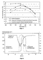
- Figure 2 shows the measured nitrogen oxide storage capabilities of the catalyst depending on the temperature of the synthesis gas.
- the thermal damage to the Nitrogen oxide storage material manifests itself in a sharp decrease in nitrogen oxide storage capacity at temperatures below 350 ° C. At higher temperatures the damage to the catalytically active components has no significant influence on nitrogen oxide storage capacity.
- the sulfurization of the Nitric oxide storage material has a decrease in overall nitrogen oxide storage capacity Temperature range between 250 and 500 ° C.
- FIGS. 3 to 5 show an exhaust gas purification system (1) with different probe configurations for performing the method according to the invention in accordance with the table.
- (2) denotes the storage catalytic converter, the function of which is to be checked regularly. It is installed in a housing of the exhaust gas cleaning system.
- probe 1 denotes a probe that measures a physical property of the catalyst, such as its complex impedance.
- the position of the probe 1 in FIG. 3 is exemplary and can be applied radially and axially over the entire catalytic converter or at several points of the catalytic converter.
- FIG. 4 shows an arrangement with a nitrogen oxide probe (probe 2) behind the catalytic converter, while FIG.
- lambda jump probes for example, two lambda jump probes, one of which is arranged in front of the catalytic converter and one behind the catalytic converter.
- lambda jump probes lambda linear probes, hydrogen probes, hydrocarbon probes and carbon monoxide probes can be used in this arrangement.
- the time differences ⁇ t 1 and ⁇ t 2 are measured.
- the probe arranged in front of the catalytic converter serves to determine the point in time at which the air ratio of the exhaust gas switches from lean to rich, or from rich to lean.
- the probe in front of the catalytic converter can be dispensed with if the switchover time is taken from the engine control.
- FIG. 6 shows the course of the measured by a lambda linear probe Engine electronics imprinted air number in front of the storage catalytic converter as well as the probe voltages the jump probe 3 before the catalyst and the jump probe 4 behind the Catalyst.
- the air ratio has a value above 1 during the majority of the operation (here 1.4).
- nitrogen oxides are released by the nitrogen oxide storage function of the catalyst and oxygen through the oxygen storage function of the catalyst stored on the catalyst.
- the nitrogen oxide storage of the catalytic converter After a certain time, the nitrogen oxide storage of the catalytic converter has filled up and it must be regenerated. For this purpose, the air ratio from the engine control to one Lowered value below 1 (here 0.75). Accordingly, the signal from probe 3 changes corresponding to the catalyst. Due to the now reducing exhaust gas decomposed and desorbed nitrogen oxides stored on the storage catalyst and the oxygen stored on the catalyst for the oxidation of the reductive components of the exhaust gas consumed. It is only after the storage materials have been regenerated a breakthrough of the rich exhaust gas through the catalyst and accordingly to one corresponding increase in the signal of the probe 4.
- the two front edges of the probe signals show a time offset .DELTA.t 1 , which is caused by the nitrogen oxide storage capacity and possibly the oxygen storage capacity of the catalyst. The more the memory functions are damaged, the shorter the time offset ⁇ t 1 .
- probe 4 After completion of the regeneration phase, the air ratio is raised again to a value above 1, which leads to the probe voltage of probe 3 springing back to zero.
- probe 4 still shows a substoichiometric air number behind the catalytic converter for a certain time, since the oxygen of the lean exhaust gas is first used to replenish the oxygen storage of the catalytic converter before it can freely pass the catalytic converter and the signal from probe 4 in its Initial state returns. As a result, a time offset ⁇ t 2 occurs between the two rear edges of the probe signals.
- the time offset ⁇ t 2 is only dependent on the oxygen storage capacity of the catalyst. By measuring this time, a judgment can thus be made about the state of the oxygen storage function of the catalytic converter. The lower the ⁇ t 2 , the lower the remaining oxygen storage capacity of the catalyst.
Landscapes
- Engineering & Computer Science (AREA)
- Chemical & Material Sciences (AREA)
- Combustion & Propulsion (AREA)
- Mechanical Engineering (AREA)
- General Engineering & Computer Science (AREA)
- Chemical Kinetics & Catalysis (AREA)
- Health & Medical Sciences (AREA)
- Emergency Medicine (AREA)
- Exhaust Gas After Treatment (AREA)
- Exhaust Gas Treatment By Means Of Catalyst (AREA)
- Investigating Or Analyzing Materials By The Use Of Electric Means (AREA)
- Combined Controls Of Internal Combustion Engines (AREA)
- Measuring Oxygen Concentration In Cells (AREA)
- Investigating Or Analysing Materials By The Use Of Chemical Reactions (AREA)
- Catalysts (AREA)
- Investigating Or Analyzing Non-Biological Materials By The Use Of Chemical Means (AREA)
Applications Claiming Priority (2)
| Application Number | Priority Date | Filing Date | Title |
|---|---|---|---|
| DE10017940 | 2000-04-11 | ||
| DE10017940A DE10017940C2 (de) | 2000-04-11 | 2000-04-11 | Verfahren zur Überprüfung der Funktionstüchtigkeit eines Stickoxid-Speicherkatalysators |
Publications (3)
| Publication Number | Publication Date |
|---|---|
| EP1146207A2 true EP1146207A2 (fr) | 2001-10-17 |
| EP1146207A3 EP1146207A3 (fr) | 2003-08-06 |
| EP1146207B1 EP1146207B1 (fr) | 2004-06-30 |
Family
ID=7638335
Family Applications (1)
| Application Number | Title | Priority Date | Filing Date |
|---|---|---|---|
| EP01108460A Expired - Lifetime EP1146207B1 (fr) | 2000-04-11 | 2001-04-04 | Procédé pour le contrôle du fonctionnement d'un catalyseur d'accumulation d'oxydes d'azote |
Country Status (5)
| Country | Link |
|---|---|
| US (1) | US6684628B2 (fr) |
| EP (1) | EP1146207B1 (fr) |
| JP (1) | JP4903947B2 (fr) |
| AT (1) | ATE270385T1 (fr) |
| DE (2) | DE10017940C2 (fr) |
Cited By (4)
| Publication number | Priority date | Publication date | Assignee | Title |
|---|---|---|---|---|
| DE102004007523B4 (de) * | 2004-02-17 | 2007-10-25 | Umicore Ag & Co. Kg | Verfahren zur Bestimmung des Umschaltzeitpunktes von der Speicherphase zur Regenerationsphase eines Stickoxid-Speicherkatalysators und zur Diagnose seines Speicherverhaltens |
| FR2943382A1 (fr) * | 2009-03-19 | 2010-09-24 | Renault Sas | Procede de gestion d'un piege a oxydes d'azote et dispositif de piege associe |
| EP2149686A4 (fr) * | 2007-05-16 | 2011-06-01 | Isuzu Motors Ltd | Procédé de commande d'un système de purification de nox et système de purification de nox |
| CN104018925A (zh) * | 2013-03-01 | 2014-09-03 | 罗伯特·博世有限公司 | 用于监控氧化氮-存储催化器的方法和装置 |
Families Citing this family (38)
| Publication number | Priority date | Publication date | Assignee | Title |
|---|---|---|---|---|
| DE10201989A1 (de) * | 2002-01-21 | 2003-07-31 | Bosch Gmbh Robert | Verfahren zum Betreiben einer Brennkraftmaschine und Brennkraftmaschine |
| JP3918706B2 (ja) * | 2002-10-04 | 2007-05-23 | 三菱自動車工業株式会社 | 内燃機関の触媒劣化検出装置 |
| DE10308287B4 (de) * | 2003-02-26 | 2006-11-30 | Umicore Ag & Co. Kg | Verfahren zur Abgasreinigung |
| RU2235563C1 (ru) * | 2003-06-05 | 2004-09-10 | Закрытое акционерное общество "АТОМ-МЕД ЦЕНТР" | Способ повышения работоспособности |
| US7490464B2 (en) * | 2003-11-04 | 2009-02-17 | Basf Catalysts Llc | Emissions treatment system with NSR and SCR catalysts |
| AT412846B (de) * | 2003-11-13 | 2005-08-25 | Treibacher Ind Ag | Abgaskatalysatorzusammensetzung |
| DE102004060125B4 (de) * | 2004-12-13 | 2007-11-08 | Audi Ag | Verfahren zur Steuerung der Be- und Entladung des Sauerstoffspeichers eines Abgaskatalysators |
| US7552587B2 (en) * | 2005-02-03 | 2009-06-30 | Basf Catalysts Llc | Deflector plate to enhance fluid stream contact with a catalyst |
| JP4192905B2 (ja) * | 2005-03-04 | 2008-12-10 | トヨタ自動車株式会社 | 内燃機関の排気浄化装置 |
| JP4462107B2 (ja) * | 2005-05-19 | 2010-05-12 | トヨタ自動車株式会社 | 内燃機関の排気浄化装置 |
| JP4363398B2 (ja) * | 2005-12-08 | 2009-11-11 | トヨタ自動車株式会社 | 内燃機関の空燃比制御装置 |
| US7597091B2 (en) | 2005-12-08 | 2009-10-06 | Toyota Jidosha Kabushiki Kaisha | Air-fuel ratio control apparatus and method for an internal combustion engine |
| JP4371114B2 (ja) * | 2006-02-28 | 2009-11-25 | トヨタ自動車株式会社 | 内燃機関の排気浄化装置 |
| DE102006025050B4 (de) * | 2006-05-27 | 2014-04-03 | Fev Gmbh | Verfahren und Vorrichtung zum Betrieb einer Abgasnachbehandlungsanlage |
| US8065871B1 (en) | 2007-01-02 | 2011-11-29 | Cummins Ip, Inc | Apparatus, system, and method for real-time diagnosis of a NOx-adsorption catalyst |
| US9358525B2 (en) * | 2008-12-04 | 2016-06-07 | Johnson Matthey Public Limited Company | NOx storage materials for sensor applications |
| DE102010027983B4 (de) * | 2010-04-20 | 2022-03-10 | Robert Bosch Gmbh | Verfahren zum Betreiben einer Brennkraftmaschine zum Abgleich einer Abgassonde |
| US8756922B2 (en) | 2011-06-10 | 2014-06-24 | Cummins Ip, Inc. | NOx adsorber catalyst condition evaluation apparatus and associated methods |
| DE102013019025A1 (de) | 2013-11-13 | 2015-05-13 | Daimler Ag | Verfahren zum Betreiben eines Abgasreinigungssystems einer Brennkraftmaschine |
| DE102015200769A1 (de) * | 2015-01-20 | 2016-07-21 | Ford Global Technologies, Llc | Verfahren zur Überwachung einer Abgasnachbehandlungsanlage eines Kraftfahrzeugs mit einem hybridelektrischen Antrieb sowie Steuerungseinrichtung für einen hybridelektrischen Antrieb |
| DE102015200751B4 (de) * | 2015-01-20 | 2021-03-04 | Ford Global Technologies, Llc | Verfahren zur Überwachung einer Abgasnachbehandlungsanlage eines Verbrennungsmotors sowie Steuerungseinrichtung für eine Abgasnachbehandlungsanlage |
| DE102016210143B4 (de) | 2015-06-12 | 2024-02-29 | Ford Global Technologies, Llc | Verfahren zur Ermittlung eines Alterungszustands eines NOx-Speicherkatalysators einer Abgasnachbehandlungsanlage eines für einen Magerbetrieb ausgelegten Verbrennungsmotors sowie Steuerungseinrichtung |
| DE202015008716U1 (de) * | 2015-12-18 | 2017-03-21 | GM Global Technology Operations LLC (n. d. Ges. d. Staates Delaware) | Computerprogramm zur Steuerung eines Vorgangs zur Regeneration einer NOx -Falle für den Magerbetrieb |
| KR102459575B1 (ko) * | 2016-01-06 | 2022-10-27 | 삼성디스플레이 주식회사 | 표시 장치 |
| DE102017200145B4 (de) * | 2016-01-22 | 2021-12-23 | Ford Global Technologies, Llc | Verfahren zur Überwachung einer Abgasnachbehandlungsanlage, insbesondere eines NOx-Speicher-Katalysators sowie Steuerungseinrichtung für eine Abgasnachbehandlungsanlage und Fahrzeug |
| JP6865138B2 (ja) * | 2017-08-31 | 2021-04-28 | 株式会社小松製作所 | 排ガス処理装置の判定方法及び排ガス処理装置の判定システム |
| DE102019200367B4 (de) | 2019-01-15 | 2025-03-27 | Ford Global Technologies, Llc | Verfahren zum Bestimmen von Regenerationsparameterwerten eines Mehrfach-LNT-Katalysatorsystems und Vorrichtung zur Datenverarbeitung |
| US11760170B2 (en) | 2020-08-20 | 2023-09-19 | Denso International America, Inc. | Olfaction sensor preservation systems and methods |
| US12269315B2 (en) | 2020-08-20 | 2025-04-08 | Denso International America, Inc. | Systems and methods for measuring and managing odor brought into rental vehicles |
| US11813926B2 (en) | 2020-08-20 | 2023-11-14 | Denso International America, Inc. | Binding agent and olfaction sensor |
| US12017506B2 (en) | 2020-08-20 | 2024-06-25 | Denso International America, Inc. | Passenger cabin air control systems and methods |
| US11881093B2 (en) | 2020-08-20 | 2024-01-23 | Denso International America, Inc. | Systems and methods for identifying smoking in vehicles |
| US11828210B2 (en) | 2020-08-20 | 2023-11-28 | Denso International America, Inc. | Diagnostic systems and methods of vehicles using olfaction |
| US11636870B2 (en) | 2020-08-20 | 2023-04-25 | Denso International America, Inc. | Smoking cessation systems and methods |
| US12251991B2 (en) | 2020-08-20 | 2025-03-18 | Denso International America, Inc. | Humidity control for olfaction sensors |
| US11932080B2 (en) | 2020-08-20 | 2024-03-19 | Denso International America, Inc. | Diagnostic and recirculation control systems and methods |
| US11760169B2 (en) | 2020-08-20 | 2023-09-19 | Denso International America, Inc. | Particulate control systems and methods for olfaction sensors |
| US12377711B2 (en) | 2020-08-20 | 2025-08-05 | Denso International America, Inc. | Vehicle feature control systems and methods based on smoking |
Citations (2)
| Publication number | Priority date | Publication date | Assignee | Title |
|---|---|---|---|---|
| EP0560991B1 (fr) | 1991-10-03 | 1997-07-30 | Toyota Jidosha Kabushiki Kaisha | Dispositif pour purifier les gaz d'echappement d'un moteur a combustion interne |
| DE19816175A1 (de) | 1998-04-14 | 1999-10-21 | Degussa | Verfahren zur Überprüfung der Funktionstüchtigkeit eines Stickoxid-Speicherkatalysators |
Family Cites Families (15)
| Publication number | Priority date | Publication date | Assignee | Title |
|---|---|---|---|---|
| NZ244890A (en) * | 1992-01-06 | 1994-07-26 | Grace W R & Co | Metalworking fluid fresh components added in-line between filtration and metalworking stations |
| EP0598917B2 (fr) * | 1992-06-12 | 2009-04-15 | Toyota Jidosha Kabushiki Kaisha | Systeme de limitation d'emission de gaz d'echappement pour moteur a combustion interne |
| US5426934A (en) * | 1993-02-10 | 1995-06-27 | Hitachi America, Ltd. | Engine and emission monitoring and control system utilizing gas sensors |
| JP2888124B2 (ja) * | 1994-01-27 | 1999-05-10 | トヨタ自動車株式会社 | 内燃機関の排気浄化装置 |
| JP3440654B2 (ja) * | 1994-11-25 | 2003-08-25 | トヨタ自動車株式会社 | 排気浄化装置 |
| DE19543219C1 (de) * | 1995-11-20 | 1996-12-05 | Daimler Benz Ag | Verfahren zum Betreiben eines Dieselmotors |
| US6161378A (en) * | 1996-06-10 | 2000-12-19 | Hitachi, Ltd. | Exhaust gas purification apparatus of internal combustion engine and catalyst for purifying exhaust gas internal combustion engine |
| JP3956437B2 (ja) * | 1996-09-26 | 2007-08-08 | マツダ株式会社 | 排気ガス浄化用触媒 |
| DE19714715A1 (de) * | 1997-04-09 | 1998-10-15 | Emitec Emissionstechnologie | Verfahren und Vorrichtung zur Überwachung eines NOx-Speichers |
| JPH1176827A (ja) * | 1997-09-09 | 1999-03-23 | Mazda Motor Corp | 排気ガス浄化装置 |
| DE19805928C2 (de) * | 1998-02-13 | 2002-12-05 | Daimler Chrysler Ag | Verfahren zur Bestimmung des Füllgrads oder der Güte eines Gase speichernden Katalysators |
| DE19823921A1 (de) * | 1998-05-28 | 1999-12-02 | Siemens Ag | Verfahren zur Überprüfung des Wirkungsgrades eines NOx-Speicherkatalysators |
| US6350421B1 (en) * | 1998-08-24 | 2002-02-26 | Dmc2 Degussa Metals Catalysts Cerdec Ag | Nitrogen oxide storage material and nitrogen oxide storing catalyst prepared therefrom |
| DE19844178A1 (de) * | 1998-09-25 | 2000-03-30 | Bosch Gmbh Robert | Katalysatordiagnoseverfahren |
| US6375910B1 (en) * | 1999-04-02 | 2002-04-23 | Engelhard Corporation | Multi-zoned catalytic trap and methods of making and using the same |
-
2000
- 2000-04-11 DE DE10017940A patent/DE10017940C2/de not_active Expired - Fee Related
-
2001
- 2001-04-04 EP EP01108460A patent/EP1146207B1/fr not_active Expired - Lifetime
- 2001-04-04 AT AT01108460T patent/ATE270385T1/de not_active IP Right Cessation
- 2001-04-04 DE DE50102707T patent/DE50102707D1/de not_active Expired - Lifetime
- 2001-04-11 US US09/832,332 patent/US6684628B2/en not_active Expired - Lifetime
- 2001-04-11 JP JP2001113174A patent/JP4903947B2/ja not_active Expired - Fee Related
Patent Citations (2)
| Publication number | Priority date | Publication date | Assignee | Title |
|---|---|---|---|---|
| EP0560991B1 (fr) | 1991-10-03 | 1997-07-30 | Toyota Jidosha Kabushiki Kaisha | Dispositif pour purifier les gaz d'echappement d'un moteur a combustion interne |
| DE19816175A1 (de) | 1998-04-14 | 1999-10-21 | Degussa | Verfahren zur Überprüfung der Funktionstüchtigkeit eines Stickoxid-Speicherkatalysators |
Cited By (5)
| Publication number | Priority date | Publication date | Assignee | Title |
|---|---|---|---|---|
| DE102004007523B4 (de) * | 2004-02-17 | 2007-10-25 | Umicore Ag & Co. Kg | Verfahren zur Bestimmung des Umschaltzeitpunktes von der Speicherphase zur Regenerationsphase eines Stickoxid-Speicherkatalysators und zur Diagnose seines Speicherverhaltens |
| EP2149686A4 (fr) * | 2007-05-16 | 2011-06-01 | Isuzu Motors Ltd | Procédé de commande d'un système de purification de nox et système de purification de nox |
| US8109080B2 (en) | 2007-05-16 | 2012-02-07 | Isuzu Motors Limited | Method of controlling NOx purification system and NOx purification system |
| FR2943382A1 (fr) * | 2009-03-19 | 2010-09-24 | Renault Sas | Procede de gestion d'un piege a oxydes d'azote et dispositif de piege associe |
| CN104018925A (zh) * | 2013-03-01 | 2014-09-03 | 罗伯特·博世有限公司 | 用于监控氧化氮-存储催化器的方法和装置 |
Also Published As
| Publication number | Publication date |
|---|---|
| DE10017940A1 (de) | 2001-10-25 |
| JP4903947B2 (ja) | 2012-03-28 |
| EP1146207A3 (fr) | 2003-08-06 |
| EP1146207B1 (fr) | 2004-06-30 |
| DE50102707D1 (de) | 2004-08-05 |
| DE10017940C2 (de) | 2003-01-23 |
| ATE270385T1 (de) | 2004-07-15 |
| JP2002047919A (ja) | 2002-02-15 |
| US6684628B2 (en) | 2004-02-03 |
| US20020012623A1 (en) | 2002-01-31 |
Similar Documents
| Publication | Publication Date | Title |
|---|---|---|
| EP1146207B1 (fr) | Procédé pour le contrôle du fonctionnement d'un catalyseur d'accumulation d'oxydes d'azote | |
| EP0950801B1 (fr) | Procédé pour la détection de la détérioration d'un catalyseur adsorbant d'oxydes d'azote | |
| DE3807907C2 (fr) | ||
| EP1098694B1 (fr) | PROCEDE DE REGENERATION D'UN CATALYSEUR ACCUMULATEUR DE NOx | |
| DE69730560T2 (de) | Verfahren zur Steuerung des Abgassystems einer Brennkraftmaschine und zum Feststellen der Verschlechterung des Katalysators/Absorptionsmittels | |
| DE2928249C2 (fr) | ||
| DE10345405B4 (de) | Katalysatorverschlechterungs-Detektionsvorrichtung | |
| DE112005001392B4 (de) | Geschichteter Katalysator zur Abgasbehandlung | |
| DE60122204T2 (de) | Dreiwegekatalysator-zusammensetzung mit manganhaltiger sauerstoffspeicherkomponente | |
| DE102012218728B4 (de) | Verfahren zur Überwachung eines Speicherkatalysators einer Brennkraftmaschine | |
| EP2322773B1 (fr) | Procédé destiné au nettoyage de gaz d'échappement de moteurs à combustion | |
| EP0928890A2 (fr) | Procédé d'exploitation d'un catalyseur de stockage de NOx | |
| EP1391600B1 (fr) | Procédé pour la désulfuration d'un catalyseur d'accumulation des oxydes d'azote | |
| EP0945608A2 (fr) | Procédé d'opération d'un dispositif d'épuration des gaz d'échappement comprenant un piège de soufre et un catalyseur d'accumulation des oxydes d'azote | |
| EP0974002A1 (fr) | PROCEDE ET DISPOSITIF DE SURVEILLANCE D'UN ACCUMULATEUR DE NOx | |
| EP0358125A2 (fr) | Catalyseur pour gaz d'échappement ayant une tendance réduite au stockage des émissions de l'anhydride sulfureux et de l'hydrogène sulfuré | |
| DE102004007523B4 (de) | Verfahren zur Bestimmung des Umschaltzeitpunktes von der Speicherphase zur Regenerationsphase eines Stickoxid-Speicherkatalysators und zur Diagnose seines Speicherverhaltens | |
| EP1008847A2 (fr) | Capteur de gaz résistif et son procédé de fabrication | |
| EP0943786B1 (fr) | Procédé de commande d'un dispositif de traitement des gaz d'échappement pour un moteur Otto à injection directe et pour un moteur à combustion de mélange faible | |
| EP1158146A2 (fr) | Procédé de fonctionnement d'un dispositif de purification des gaz d'échappement dans un moteur à allumage commandé | |
| EP1196684B1 (fr) | PROCEDE DE COMMANDE DE LA REGENERATION D'UN CATALYSEUR ACCUMULATEUR DE NOx | |
| DE10125759B4 (de) | Verfahren zur Ermittlung eines Beladungszustandes eines NOx-Speicherkatalysators | |
| DE102004009984A1 (de) | Vorrichtung und Verfahren für die Steuerung eines Innenverbrennungsmotors | |
| DE102004007666B4 (de) | Vorrichtung und Verfahren für die Steuerung eines Innenverbrennungsmotors | |
| DE10156476B4 (de) | Verfahren zur Erkennung der fortschreitenden Verschwefelung eines NOx-Speicherkatalysators |
Legal Events
| Date | Code | Title | Description |
|---|---|---|---|
| PUAI | Public reference made under article 153(3) epc to a published international application that has entered the european phase |
Free format text: ORIGINAL CODE: 0009012 |
|
| 17P | Request for examination filed |
Effective date: 20010404 |
|
| AK | Designated contracting states |
Kind code of ref document: A2 Designated state(s): AT BE CH CY DE DK ES FI FR GB GR IE IT LI LU MC NL PT SE TR |
|
| AX | Request for extension of the european patent |
Free format text: AL;LT;LV;MK;RO;SI |
|
| RAP1 | Party data changed (applicant data changed or rights of an application transferred) |
Owner name: OMG AG & CO. KG |
|
| PUAL | Search report despatched |
Free format text: ORIGINAL CODE: 0009013 |
|
| AK | Designated contracting states |
Designated state(s): AT BE CH CY DE DK ES FI FR GB GR IE IT LI LU MC NL PT SE TR |
|
| AX | Request for extension of the european patent |
Extension state: AL LT LV MK RO SI |
|
| RIC1 | Information provided on ipc code assigned before grant |
Ipc: 7F 02D 41/14 B Ipc: 7F 02D 41/02 B Ipc: 7F 01N 11/00 A Ipc: 7F 01N 3/08 B |
|
| GRAP | Despatch of communication of intention to grant a patent |
Free format text: ORIGINAL CODE: EPIDOSNIGR1 |
|
| RAP1 | Party data changed (applicant data changed or rights of an application transferred) |
Owner name: UMICORE AG & CO. KG |
|
| GRAS | Grant fee paid |
Free format text: ORIGINAL CODE: EPIDOSNIGR3 |
|
| AKX | Designation fees paid |
Designated state(s): AT BE CH CY DE DK ES FI FR GB GR IE IT LI LU MC NL PT SE TR |
|
| GRAA | (expected) grant |
Free format text: ORIGINAL CODE: 0009210 |
|
| RTI1 | Title (correction) |
Free format text: PROCESS FOR CHECKING THE FUNCTIONING OF A NITROGEN OXIDE STORAGE CATALYST |
|
| AK | Designated contracting states |
Kind code of ref document: B1 Designated state(s): AT BE CH CY DE DK ES FI FR GB GR IE IT LI LU MC NL PT SE TR |
|
| PG25 | Lapsed in a contracting state [announced via postgrant information from national office to epo] |
Ref country code: NL Free format text: LAPSE BECAUSE OF FAILURE TO SUBMIT A TRANSLATION OF THE DESCRIPTION OR TO PAY THE FEE WITHIN THE PRESCRIBED TIME-LIMIT Effective date: 20040630 Ref country code: FI Free format text: LAPSE BECAUSE OF FAILURE TO SUBMIT A TRANSLATION OF THE DESCRIPTION OR TO PAY THE FEE WITHIN THE PRESCRIBED TIME-LIMIT Effective date: 20040630 Ref country code: TR Free format text: LAPSE BECAUSE OF FAILURE TO SUBMIT A TRANSLATION OF THE DESCRIPTION OR TO PAY THE FEE WITHIN THE PRESCRIBED TIME-LIMIT Effective date: 20040630 Ref country code: IE Free format text: LAPSE BECAUSE OF FAILURE TO SUBMIT A TRANSLATION OF THE DESCRIPTION OR TO PAY THE FEE WITHIN THE PRESCRIBED TIME-LIMIT Effective date: 20040630 |
|
| REG | Reference to a national code |
Ref country code: CH Ref legal event code: EP Ref country code: GB Ref legal event code: FG4D Free format text: NOT ENGLISH |
|
| REG | Reference to a national code |
Ref country code: IE Ref legal event code: FG4D Free format text: GERMAN |
|
| REF | Corresponds to: |
Ref document number: 50102707 Country of ref document: DE Date of ref document: 20040805 Kind code of ref document: P |
|
| GBT | Gb: translation of ep patent filed (gb section 77(6)(a)/1977) |
Effective date: 20040802 |
|
| PG25 | Lapsed in a contracting state [announced via postgrant information from national office to epo] |
Ref country code: SE Free format text: LAPSE BECAUSE OF FAILURE TO SUBMIT A TRANSLATION OF THE DESCRIPTION OR TO PAY THE FEE WITHIN THE PRESCRIBED TIME-LIMIT Effective date: 20040930 Ref country code: GR Free format text: LAPSE BECAUSE OF FAILURE TO SUBMIT A TRANSLATION OF THE DESCRIPTION OR TO PAY THE FEE WITHIN THE PRESCRIBED TIME-LIMIT Effective date: 20040930 Ref country code: DK Free format text: LAPSE BECAUSE OF FAILURE TO SUBMIT A TRANSLATION OF THE DESCRIPTION OR TO PAY THE FEE WITHIN THE PRESCRIBED TIME-LIMIT Effective date: 20040930 |
|
| PG25 | Lapsed in a contracting state [announced via postgrant information from national office to epo] |
Ref country code: ES Free format text: LAPSE BECAUSE OF FAILURE TO SUBMIT A TRANSLATION OF THE DESCRIPTION OR TO PAY THE FEE WITHIN THE PRESCRIBED TIME-LIMIT Effective date: 20041011 |
|
| ET | Fr: translation filed | ||
| NLV1 | Nl: lapsed or annulled due to failure to fulfill the requirements of art. 29p and 29m of the patents act | ||
| REG | Reference to a national code |
Ref country code: IE Ref legal event code: FD4D |
|
| PG25 | Lapsed in a contracting state [announced via postgrant information from national office to epo] |
Ref country code: LU Free format text: LAPSE BECAUSE OF NON-PAYMENT OF DUE FEES Effective date: 20050404 Ref country code: CY Free format text: LAPSE BECAUSE OF FAILURE TO SUBMIT A TRANSLATION OF THE DESCRIPTION OR TO PAY THE FEE WITHIN THE PRESCRIBED TIME-LIMIT Effective date: 20050404 Ref country code: AT Free format text: LAPSE BECAUSE OF NON-PAYMENT OF DUE FEES Effective date: 20050404 |
|
| PG25 | Lapsed in a contracting state [announced via postgrant information from national office to epo] |
Ref country code: CH Free format text: LAPSE BECAUSE OF NON-PAYMENT OF DUE FEES Effective date: 20050430 Ref country code: BE Free format text: LAPSE BECAUSE OF NON-PAYMENT OF DUE FEES Effective date: 20050430 Ref country code: MC Free format text: LAPSE BECAUSE OF NON-PAYMENT OF DUE FEES Effective date: 20050430 Ref country code: LI Free format text: LAPSE BECAUSE OF NON-PAYMENT OF DUE FEES Effective date: 20050430 |
|
| PLBE | No opposition filed within time limit |
Free format text: ORIGINAL CODE: 0009261 |
|
| STAA | Information on the status of an ep patent application or granted ep patent |
Free format text: STATUS: NO OPPOSITION FILED WITHIN TIME LIMIT |
|
| 26N | No opposition filed |
Effective date: 20050331 |
|
| BERE | Be: lapsed |
Owner name: *UMICORE A.G. & CO. K.G. Effective date: 20050430 |
|
| REG | Reference to a national code |
Ref country code: CH Ref legal event code: PL |
|
| BERE | Be: lapsed |
Owner name: *UMICORE A.G. & CO. K.G. Effective date: 20050430 |
|
| PG25 | Lapsed in a contracting state [announced via postgrant information from national office to epo] |
Ref country code: PT Free format text: LAPSE BECAUSE OF NON-PAYMENT OF DUE FEES Effective date: 20041130 |
|
| REG | Reference to a national code |
Ref country code: FR Ref legal event code: PLFP Year of fee payment: 16 |
|
| REG | Reference to a national code |
Ref country code: FR Ref legal event code: PLFP Year of fee payment: 17 |
|
| REG | Reference to a national code |
Ref country code: FR Ref legal event code: PLFP Year of fee payment: 18 |
|
| PGFP | Annual fee paid to national office [announced via postgrant information from national office to epo] |
Ref country code: GB Payment date: 20180329 Year of fee payment: 18 |
|
| PGFP | Annual fee paid to national office [announced via postgrant information from national office to epo] |
Ref country code: FR Payment date: 20180315 Year of fee payment: 18 |
|
| PGFP | Annual fee paid to national office [announced via postgrant information from national office to epo] |
Ref country code: DE Payment date: 20180320 Year of fee payment: 18 |
|
| PGFP | Annual fee paid to national office [announced via postgrant information from national office to epo] |
Ref country code: IT Payment date: 20180420 Year of fee payment: 18 |
|
| REG | Reference to a national code |
Ref country code: DE Ref legal event code: R119 Ref document number: 50102707 Country of ref document: DE |
|
| GBPC | Gb: european patent ceased through non-payment of renewal fee |
Effective date: 20190404 |
|
| PG25 | Lapsed in a contracting state [announced via postgrant information from national office to epo] |
Ref country code: DE Free format text: LAPSE BECAUSE OF NON-PAYMENT OF DUE FEES Effective date: 20191101 Ref country code: GB Free format text: LAPSE BECAUSE OF NON-PAYMENT OF DUE FEES Effective date: 20190404 |
|
| PG25 | Lapsed in a contracting state [announced via postgrant information from national office to epo] |
Ref country code: FR Free format text: LAPSE BECAUSE OF NON-PAYMENT OF DUE FEES Effective date: 20190430 |
|
| PG25 | Lapsed in a contracting state [announced via postgrant information from national office to epo] |
Ref country code: IT Free format text: LAPSE BECAUSE OF NON-PAYMENT OF DUE FEES Effective date: 20190404 |