EP1146251A1 - Dispositif de réglage de l'écartement des bonnets d'un soutien-gorge - Google Patents
Dispositif de réglage de l'écartement des bonnets d'un soutien-gorge Download PDFInfo
- Publication number
- EP1146251A1 EP1146251A1 EP01440102A EP01440102A EP1146251A1 EP 1146251 A1 EP1146251 A1 EP 1146251A1 EP 01440102 A EP01440102 A EP 01440102A EP 01440102 A EP01440102 A EP 01440102A EP 1146251 A1 EP1146251 A1 EP 1146251A1
- Authority
- EP
- European Patent Office
- Prior art keywords
- cups
- adjusting
- spacing
- conduits
- locking
- Prior art date
- Legal status (The legal status is an assumption and is not a legal conclusion. Google has not performed a legal analysis and makes no representation as to the accuracy of the status listed.)
- Granted
Links
Images

Classifications
-
- F—MECHANICAL ENGINEERING; LIGHTING; HEATING; WEAPONS; BLASTING
- F16—ENGINEERING ELEMENTS AND UNITS; GENERAL MEASURES FOR PRODUCING AND MAINTAINING EFFECTIVE FUNCTIONING OF MACHINES OR INSTALLATIONS; THERMAL INSULATION IN GENERAL
- F16G—BELTS, CABLES, OR ROPES, PREDOMINANTLY USED FOR DRIVING PURPOSES; CHAINS; FITTINGS PREDOMINANTLY USED THEREFOR
- F16G11/00—Means for fastening cables or ropes to one another or to other objects; Caps or sleeves for fixing on cables or ropes
- F16G11/10—Quick-acting fastenings; Clamps holding in one direction only
- F16G11/101—Quick-acting fastenings; Clamps holding in one direction only deforming the cable by moving a part of the fastener
-
- A—HUMAN NECESSITIES
- A41—WEARING APPAREL
- A41C—CORSETS; BRASSIERES
- A41C3/00—Brassieres
- A41C3/0028—Brassieres with size and configuration adjustment means
-
- A—HUMAN NECESSITIES
- A41—WEARING APPAREL
- A41C—CORSETS; BRASSIERES
- A41C3/00—Brassieres
- A41C3/02—Brassieres with front closures
-
- A—HUMAN NECESSITIES
- A41—WEARING APPAREL
- A41F—GARMENT FASTENINGS; SUSPENDERS
- A41F1/00—Fastening devices specially adapted for garments
- A41F1/006—Brassiére fasteners
Definitions
- the present invention relates to a device for adjusting the spacing of the cups of a bra, disposed between said cups close to their internal lateral ends, and allowing on the one hand the adaptation of the bra to between the breast each user, and on the other hand the adjustment of the position of the breasts by adjustment of the tension between the cups.
- the need to adjust the distance between the breasts derives in particular from the general tendency to put forward the law of each to a certain comfort, a tendency which manifests itself in this domain by a propensity to no longer consider the bra only as an undergarment to enhance form breasts, but also as a personal element of comfort, adaptable as such and as far as possible to the physiology of the user, and the comfort of the moment.
- the enhancement of the chest can also be subject to variations during the day, especially depending on the clothes worn on the bra, or the appearance that the user wants to offer of itself in a given social context. More generally, the breast size may change from day to day in some women women, for example due to water retention problems, and require corresponding adjustments of the bra. In end of such adjustments may be a response in terms of comfort to differences in breast tenderness.
- bras of the type sold under the "Wonderbra” brand created to highlight the chest of women by enlarging the breasts on the one hand, and bringing them closer to each other on the other hand to obtain a so-called “pushing effect”, further contributed to the research a comfort solution as proposed by the invention. Indeed, the wearing of bra in the raised position and close to the breasts, providing an effect undeniable aesthetics especially for small breasts, compresses and constrains by elsewhere said breasts in a manner which can quickly cause discomfort or even be quite unpleasant after a while.
- the voltage to be printed on the cups for the realization of this effect can be released without delay when the user wants rest her breasts, for example when a reception is over.
- the existence of an adjustment can allow the same bra to be used to two different social "functions", for example for a woman chaining a reception in which the raised position is desired, after a day work during which a traditional bra is sufficient. Adjustment the distance or the tension between the breast will then save time, without the need to change a bra, which may prove to be appreciable for certain users passing practically without transition from one situation to another.
- the adjustment device of the present invention allowing as has been mentioned before to adjust the distance between the cups, is characterized mainly in that it includes means for the passage and guidance of two cords each attached to an inner lateral end of one of the cups, so that each cord is accessible upstream and downstream of the adjustment, and locking / unlocking means allow individual adjustment of the length of cord extending between said internal lateral end of the bonnet and the adjustment device, said locking / unlocking means can be activated by user-accessible control means between the cups.
- This device is therefore implemented with cords equipping the sides inside of the cups, which are themselves manipulated, upstream and downstream of the adjustment device itself, to carry out the adjustment.
- control of the cables carried out by upstream manipulation or downstream of the device, and which regulates the distance between the cups, and the control of the blocking / unblocking of the cords, which moreover precedes chronologically the first cited.
- the device of the invention comprises two separate conduits have a top opening for cord entry and an opening lower for the output thereof, the separation between the two conduits being produced by a central body of vertical appearance, the guidance being obtained by association between said central organ, side walls joining the openings upper and lower, and front and back walls.
- the separation allows individualization of the adjustment by the cords.
- the locking / unlocking means can include return means in the locking position of the cords in their drove.
- Said locking / unlocking means can for example consist of a rod contiguous to each conduit, movable in translation, rectilinear along an axis vertically between two stable positions, and provided at one of its ends a protrusion oriented so that it partially obstructs the duct when the movable rod is moved to one of its stable positions, and releases the volume of said conduit in the other of said stable positions.
- the section of cords does not differ significantly from that of conduits, at least part of the way.
- the cords should preferably adjust without too much play in at least the portion of the duct, in which takes place the obstruction caused by the growth of the stem.
- the means for controlling the means of locking / unlocking consists of a button located at one end of the rod mobile adjoining each conduit, button which allows the manipulation of said rod.
- said button is located at the top of the device for adjustment, at a level close to that of the lateral ends of the cups.
- the locking / unlocking means include means for returning to the stable position for locking the cords in their conduit, as mentioned before. Both hands are then necessary for handling and adjusting the cords, but making a correct blocking is guaranteed in all cases.
- the adjustment device of the invention comprises at least one stop limiting the movement of the rod during the establishment of the release of each bead by translation of the rod towards said stopper in order to release the volume of each duct. It is indeed functionally necessary to limit the rectilinear movement of the locking / unlocking rod, in order to be able perform this last function in good conditions.
- the central organ for separating the two conduits includes said blocking / unblocking means operating simultaneously for the two conduits.
- This central body then performs two functions: the separation of conduits, and blocking / unblocking.
- the adjustment device of the invention consists of two parallel flat plates separated by leaves by two side walls forming an acute angle with the axis of the central organ, and on the other hand by two upper and lower walls of horizontal appearance delimiting on the one hand with the side walls the upper and lower openings of the conduits, and cooperating on the other hand with the locking / unlocking means for allow them to take their blocking position and unlocking.
- the lateral ends of the wall overlap the upper ends of the side walls, creating laterally oriented upper duct openings.
- the lower ends of the side walls are substantially at same level as the side ends of the bottom wall, creating lower duct openings facing down.
- This relative arrangement of the end orifices of the conduits in fact reflects a adaptation to the natural orientation of the cords, which present upstream of the device a substantially horizontal orientation, while their weight makes them approximately vertical after the exit of said device, although at exit proper, their orientation depends on the exit angle of the conduit.
- the upstream section is functionally horizontal in appearance because it is the part which primarily carries out the tension between the cups: in the absence of the setting of the invention, a single cord or equivalent would connect said caps, according to a horizontal axis. The function remains, improved, and the orientation does not not change.
- the device of the invention also allows the exercise of lateral forces applying to the internal border of the cups, which affect the general balance of the latter and improve the implementation breast shape, in combination with other forces acting on the periphery of each cap, due for example to the straps or to the side fasteners.
- the upper wall as defined previously may include an orifice passage for the locking / unlocking means, and serves as a stop for the means for controlling said blocking / unblocking means of the cords.
- the lower wall can also serve as a stop for the lower end of said means.
- the device of the present invention preferably still has symmetry with respect to a plane vertical passing through the middle of the upper and lower walls, and perpendicular with flat plates.
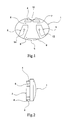
- a plate (1) has on one of its large flat faces of the protrusions intended in particular to constitute the walls of the ducts.
- two side walls (2, 3) form the outer walls of said conduits, while two walls respectively upper (4) and lower (5) in particular delimit the inlet (6, 7) and outlet (8, 9) orifices of the cords.
- the upper wall (4) includes a passage (10) for the means of blocking / unblocking (see figures 7 and 8).
- a passage (10) for the means of blocking / unblocking see figures 7 and 8.
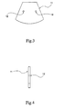
- all the aforementioned walls (2, 3, 4, 5) have the same height, so that it can be fixed there a plate (11) such as that which is represented in FIGS. 3 and 4.
- the cutting exterior of this last plate (11) can take various forms, but it must at least cover the perimeter delimited by the walls (2, 3, 4, 5) in order to constitute complete conduits on four sides for the cords.
- This plate (11) is for example provided with fixing holes (12, 13), which correspond with orifices (14, 15) made in the side walls (2, 3), for the purpose of inserting a shaft, stud, screw or equivalent for securing a element (1) on the other (11).
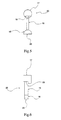
- the means or the blocking member (20) / release consist of a rod (16) limited to one of its ends by a manipulation button (17), and at the second end by a shape head (18) semi-cylindrical causing more particularly the blocking / unblocking of each cord (21, 22).
- the manipulation button (17) is for example made of a cylindrical body, part of which is truncated to form a surface forming a stop (19) bearing on the upper wall (4).
- the rod (16) is indeed intended to move in the passage (10), as it appears in Figures 7 and 8.
- the position of the member (20) is such that the cords (21, 22) do not are not blocked.
- the surface (19) is in this case in abutment on the upper wall (4), and the surface (23) limiting the semi-cylindrical head is in abutment on the wall lower (5). Said rounded shape makes it possible to release in this position the lower openings (8, 9), and the conduits are then not blocked.
- the head (18) is raised and, given the inclination of the walls (2, 3), the lateral ends of said head (18) partially obstruct the conduits, and block the cords (21, 22).
- the aforementioned surfaces (19, 23) are not then more support.
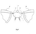
- Figure 9 shows the arrangement of the device of the invention between the cups (B1, B2), and the orientation of the sections of the cords (21, 22) located respectively upstream and downstream of said device.
- the upstream portions are substantially horizontal, while the downstream portions are generally vertical.
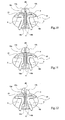
- FIGS 10 to 12 show a variant in which each conduit includes locking / unlocking means of the same type as in the variant described so far.
- the operating principle is basically the same than before, with two rods (16a, 16b) limited to their ends respective by buttons (17a, 17b) for manipulation in the upper part, and heads (18a, 18b) in the lower part.
- Their shapes are especially intended for adapt to a fixed partition (26) delimiting the two conduits, against which slide said rods (16a, 16b) and their end elements.
Landscapes
- Engineering & Computer Science (AREA)
- Textile Engineering (AREA)
- General Engineering & Computer Science (AREA)
- Mechanical Engineering (AREA)
- Corsets Or Brassieres (AREA)
- Control Of Motors That Do Not Use Commutators (AREA)
- Polarising Elements (AREA)
- General Induction Heating (AREA)
- Table Devices Or Equipment (AREA)
- Making Paper Articles (AREA)
- Beverage Vending Machines With Cups, And Gas Or Electricity Vending Machines (AREA)
- Auxiliary Devices For And Details Of Packaging Control (AREA)
- Cultivation Receptacles Or Flower-Pots, Or Pots For Seedlings (AREA)
Abstract
Description
- la figure 1 est une vue en élévation de face d'un des deux éléments, formant la pièce principale du dispositif de réglage de l'invention ;
- la figure 2 en est une vue de côté ;
- les figures 3 et 4 montrent, selon les mêmes orientations de vues que précédemment, le second élément de ladite pièce principale ;
- les figures 5 et 6 illustrent, avec encore les mêmes orientations de vues qu'auparavant, les moyens mobiles de blocage / déblocage des cordons ;
- les figures 7 et 8 montrent les positions de blocage / déblocage desdits moyens dans le premier élément ;
- la figure 9 représente une vue de face d'un dispositif de réglage de l'invention disposé entre les deux bonnets (partiellement représentés) d'un soutien-gorge ; et
- les figures 10 à 12 montrent une configuration dans laquelle chaque conduit comporte des moyens de blocage / déblocage.
Claims (14)
- Dispositif de réglage de l'écartement des bonnets (B1, B2) d'un soutien-gorge, disposé entre lesdits bonnets (B1, B2) au voisinage de leurs extrémités latérales internes, caractérisé en ce qu'il comporte des moyens pour le passage et le guidage de deux cordons (21, 22) fixés chacun à une extrémité latérale interne d'un des bonnets (B1, B2), de telle sorte que chaque cordon (21, 22) soit accessible en amont et en aval du dispositif de réglage, et des moyens de blocage / déblocage permettent un réglage individuel de la longueur de cordon (21, 22) s'étendant entre ladite extrémité latérale interne du bonnet (B1, B2) et le dispositif de réglage, lesdits moyens de blocage / déblocage pouvant être activés par des moyens de commande accessibles par l'utilisateur entre les bonnets (B1, B2).
- Dispositif de réglage de l'écartement des bonnets (B1, B2) d'un soutien-gorge selon la revendication précédente, caractérisé en ce qu'il comporte deux conduits distincts dotés d'une ouverture supérieure (6, 7) pour l'entrée du cordon (21, 22) et d'une ouverture inférieure (8, 9) pour la sortie de celui-ci, la séparation entre les deux conduits étant réalisée par un organe central (16, 26) d'allure verticale, le guidage étant obtenu par association entre ledit organe central (16, 26) et d'une part des parois latérales (2, 3) joignant les ouvertures supérieure (6, 7) et inférieure (8, 9), et d'autre part des parois frontale (1) et dorsale (11).
- Dispositif de réglage de l'écartement des bonnets (B1, B2) d'un soutien-gorge selon l'une quelconque des revendications précédentes, caractérisé en ce que les moyens de blocage / déblocage comportent des moyens de rappel en la position de blocage des cordons (21, 22) dans leur conduit.
- Dispositif de réglage de l'écartement des bonnets (B1, B2) d'un soutien-gorge selon l'une quelconque des revendications précédentes, caractérisé en ce que les moyens de blocage / déblocage consistent en une tige (16, 16a,16b) contiguë à chaque conduit, mobile en translation rectiligne selon un axe d'allure verticale entre deux positions stables, et muni à l'une de ses extrémités d'une excroissance (18, 18a, 18b) orientée de telle sorte qu'elle obstrue partiellement le conduit lorsque la tige (16, 16a, 16b) mobile est déplacée vers l'une de ses positions stables, et libère le volume dudit conduit dans l'autre desdites positions stables.
- Dispositif de réglage de l'écartement des bonnets (B1, B2) d'un soutien-gorge selon la revendication précédente, caractérisé en ce les moyens de commande des moyens de blocage / déblocage consistent en un bouton (17, 17a, 17b) situé à l'une des extrémités de la tige (16, 16a, 16b) mobile contiguë à chaque conduit, permettant la manipulation de ladite tige (16, 16a, 16b).
- Dispositif de réglage de l'écartement des bonnets (B1, B2) d'un soutien-gorge selon la revendication précédente, caractérisé en ce que ledit bouton (17, 17a, 17b) est situé à la partie supérieure du dispositif de réglage, à un niveau voisin de celui des extrémités latérales des bonnets (B1, B2).
- Dispositif de réglage de l'écartement des bonnets (B1, B2) d'un soutien-gorge selon l'une quelconque des revendications 3 à 6, caractérisé en ce qu'il comporte au moins une butée (5) limitant le mouvement de la tige (16, 16a, 16b) lors de l'établissement du déblocage de chaque cordon (21, 22) par translation de la tige (16, 16a, 16b) vers ladite butée (5) en vue de libérer le volume de chaque conduit.
- Dispositif de réglage de l'écartement des bonnets (B1, B2) d'un soutien-gorge selon l'une des revendications 2 à 7, caractérisé en ce que l'organe central (16) de séparation des deux conduits comporte les moyens de blocage / déblocage opérant simultanément pour les deux conduits.
- Dispositif de réglage de l'écartement des bonnets (B1, B2) d'un soutien-gorge selon la revendication précédente, caractérisé en ce qu'il est constitué de deux plaques (1, 11) planes parallèles séparées d'une part par deux parois latérales (2, 3) formant un angle aigu avec l'axe de l'organe central, et d'autre part par deux parois supérieure (4) et inférieure (5) d'allure horizontale délimitant d'une part avec les parois latérales (2, 3) les ouvertures supérieure (6, 7) et inférieure (8, 9) des conduits, et coopérant d'autre part avec les moyens de blocage / déblocage pour leur permettre de prendre leur position respectivement de blocage et de déblocage.
- Dispositif de réglage de l'écartement des bonnets (B1, B2) d'un soutien-gorge selon la revendication précédente, caractérisé en ce que les extrémités latérales de la paroi supérieure (4) surmontent les extrémités supérieures des parois latérales (2, 3), créant des ouvertures supérieures (6, 7) des conduits orientées latéralement.
- Dispositif de réglage de l'écartement des bonnets (B1, B2) d'un soutien-gorge selon la revendication 9, caractérisé en ce que les extrémités inférieures des parois latérales (2, 3) sont sensiblement au même niveau que les extrémités latérales de la paroi inférieure (5), créant des ouvertures inférieures (8, 9) des conduits orientés vers le bas.
- Dispositif de réglage de l'écartement des bonnets (B1, B2) d'un soutien-gorge selon l'une des revendications 9 à 11, caractérisé en ce que la paroi supérieure (4) comporte un orifice (10) de passage pour les moyens de blocage / déblocage, et sert de butée pour les moyens de commande (17) desdits moyens de blocage / déblocage des cordons (21, 22).
- Dispositif de réglage de l'écartement des bonnets (B1, B2) d'un soutien-gorge selon l'une des revendications 9 à 12, caractérisé en ce que la paroi inférieure (5) sert de butée pour l'extrémité inférieure des moyens de blocage / déblocage des cordons (21, 22).
- Dispositif de réglage de l'écartement des bonnets (B1, B2) d'un soutien-gorge selon l'une quelconque des revendications 9 à 13, caractérisé en ce qu'il présente une symétrie par rapport à un plan vertical passant par le milieu des parois supérieure (4) et inférieure (5), et perpendiculaire aux plaques planes (1, 11).
Applications Claiming Priority (2)
| Application Number | Priority Date | Filing Date | Title |
|---|---|---|---|
| FR0004855 | 2000-04-14 | ||
| FR0004855A FR2807624B1 (fr) | 2000-04-14 | 2000-04-14 | Dispositif de reglage de l'ecartement des bonnets d'un soutien-gorge |
Publications (2)
| Publication Number | Publication Date |
|---|---|
| EP1146251A1 true EP1146251A1 (fr) | 2001-10-17 |
| EP1146251B1 EP1146251B1 (fr) | 2005-10-19 |
Family
ID=8849275
Family Applications (1)
| Application Number | Title | Priority Date | Filing Date |
|---|---|---|---|
| EP01440102A Expired - Lifetime EP1146251B1 (fr) | 2000-04-14 | 2001-04-11 | Dispositif de réglage de l'écartement des bonnets d'un soutien-gorge |
Country Status (6)
| Country | Link |
|---|---|
| EP (1) | EP1146251B1 (fr) |
| AT (1) | ATE307308T1 (fr) |
| DE (1) | DE60114068T2 (fr) |
| ES (1) | ES2251451T3 (fr) |
| FR (1) | FR2807624B1 (fr) |
| HK (1) | HK1045723A1 (fr) |
Cited By (2)
| Publication number | Priority date | Publication date | Assignee | Title |
|---|---|---|---|---|
| FR2853816A1 (fr) * | 2003-04-18 | 2004-10-22 | Thabora | Dispositif d'ajustement de la distance entre les bonnets d'un soutien-gorge |
| WO2009033327A1 (fr) * | 2007-09-14 | 2009-03-19 | Kaiping Hunghon Garment Accessories Co., Ltd | Soutien gorge assemblé |
Families Citing this family (1)
| Publication number | Priority date | Publication date | Assignee | Title |
|---|---|---|---|---|
| US12063986B2 (en) | 2021-05-06 | 2024-08-20 | Nike, Inc. | Braided bra with integrated lacings |
Citations (7)
| Publication number | Priority date | Publication date | Assignee | Title |
|---|---|---|---|---|
| GB365977A (en) * | 1931-07-07 | 1932-01-28 | Lars Johan Larsson | An improved locking device for cords, ropes, straps or the like |
| GB576522A (en) * | 1943-02-01 | 1946-04-08 | Trubenised Ltd | Improvements in and relating to brassieres |
| US4102019A (en) * | 1977-03-07 | 1978-07-25 | Boden Ogden W | Locking assemblies which maintain bow loops in cords |
| US4156574A (en) * | 1978-02-06 | 1979-05-29 | Boden Ogden W | Cord lock with self locking spring feelers |
| FR2661804A1 (fr) * | 1990-05-11 | 1991-11-15 | Santoul Christian | Attache reglable pour cordonnets, lacets ou autres liens souples. |
| US5433648A (en) * | 1994-01-07 | 1995-07-18 | Frydman; Larry G. | Rotatable closure device for brassieres and hats |
| US6185798B1 (en) * | 1999-07-06 | 2001-02-13 | Huy That Anh Ton | Shoelace fastener |
-
2000
- 2000-04-14 FR FR0004855A patent/FR2807624B1/fr not_active Expired - Fee Related
-
2001
- 2001-04-11 DE DE60114068T patent/DE60114068T2/de not_active Expired - Fee Related
- 2001-04-11 EP EP01440102A patent/EP1146251B1/fr not_active Expired - Lifetime
- 2001-04-11 AT AT01440102T patent/ATE307308T1/de not_active IP Right Cessation
- 2001-04-11 ES ES01440102T patent/ES2251451T3/es not_active Expired - Lifetime
-
2002
- 2002-04-17 HK HK02102901.2A patent/HK1045723A1/zh unknown
Patent Citations (7)
| Publication number | Priority date | Publication date | Assignee | Title |
|---|---|---|---|---|
| GB365977A (en) * | 1931-07-07 | 1932-01-28 | Lars Johan Larsson | An improved locking device for cords, ropes, straps or the like |
| GB576522A (en) * | 1943-02-01 | 1946-04-08 | Trubenised Ltd | Improvements in and relating to brassieres |
| US4102019A (en) * | 1977-03-07 | 1978-07-25 | Boden Ogden W | Locking assemblies which maintain bow loops in cords |
| US4156574A (en) * | 1978-02-06 | 1979-05-29 | Boden Ogden W | Cord lock with self locking spring feelers |
| FR2661804A1 (fr) * | 1990-05-11 | 1991-11-15 | Santoul Christian | Attache reglable pour cordonnets, lacets ou autres liens souples. |
| US5433648A (en) * | 1994-01-07 | 1995-07-18 | Frydman; Larry G. | Rotatable closure device for brassieres and hats |
| US6185798B1 (en) * | 1999-07-06 | 2001-02-13 | Huy That Anh Ton | Shoelace fastener |
Cited By (3)
| Publication number | Priority date | Publication date | Assignee | Title |
|---|---|---|---|---|
| FR2853816A1 (fr) * | 2003-04-18 | 2004-10-22 | Thabora | Dispositif d'ajustement de la distance entre les bonnets d'un soutien-gorge |
| WO2004093577A3 (fr) * | 2003-04-18 | 2004-12-29 | Thabora | Dispositif d’ajustement de la distance entre les bonnets d’un soutien-gorge |
| WO2009033327A1 (fr) * | 2007-09-14 | 2009-03-19 | Kaiping Hunghon Garment Accessories Co., Ltd | Soutien gorge assemblé |
Also Published As
| Publication number | Publication date |
|---|---|
| ATE307308T1 (de) | 2005-11-15 |
| FR2807624B1 (fr) | 2002-09-20 |
| ES2251451T3 (es) | 2006-05-01 |
| DE60114068T2 (de) | 2006-07-20 |
| DE60114068D1 (de) | 2006-03-02 |
| EP1146251B1 (fr) | 2005-10-19 |
| HK1045723A1 (zh) | 2002-12-06 |
| FR2807624A1 (fr) | 2001-10-19 |
Similar Documents
| Publication | Publication Date | Title |
|---|---|---|
| FR2498912A1 (fr) | Cadre pour l'exposition d'objets | |
| EP3122299A1 (fr) | Masque de protection des yeux, notamment pour la pratique du ski | |
| EP1138879A1 (fr) | Disque rotorique de turbine équipé d'ailettes à pied de sapin et procédé de montage d'une ailette sur un disque | |
| CH620582A5 (fr) | ||
| EP1146251B1 (fr) | Dispositif de réglage de l'écartement des bonnets d'un soutien-gorge | |
| BE1021494B1 (fr) | Dispositif servant a inserer des touffes de poils dans des orifices de reception de touffe d'un corps de support | |
| CA113434S (en) | Spout | |
| CH628934A5 (fr) | Relais actif d'une machine a tisser sans navette a insertion de trame pneumatique. | |
| EP0115364A2 (fr) | Fermoir de bracelet à boucle déployante | |
| CH615341A5 (fr) | ||
| EP0586491A1 (fr) | Sac à dos | |
| BE1010588A4 (fr) | Support de batonnet sanitaire pour cuvette sanitaire. | |
| FR2661240A1 (fr) | Diffuseur d'air equipe d'un dispositif de reglage de l'orientation du flux d'air, notamment pour l'equipement de vehicule. | |
| CA2968166A1 (fr) | Dispositif amovible pour eliminer la boucle des lacets et pour bloquer les lacets | |
| FR2661809A3 (fr) | Diffuseur personnel de parfum ou de desodorisant. | |
| EP1696753A1 (fr) | Dispositif de reglage d'un soutien-gorge | |
| WO2002019854A1 (fr) | Dispositif de protection solaire repliable | |
| FR2621457A1 (fr) | Sous-vetement masculin a montage ameliore de la poche de maintien des organes genitaux | |
| EP3636857B1 (fr) | Dispositif d'écrémage de piscine et piscine munie de celui-ci | |
| FR2906439A1 (fr) | Chassis pour panier-siege de pecheur | |
| FR2600242A1 (fr) | Porte-pots ou porte-jardinieres expansibles pour balustrades | |
| EP3801371B1 (fr) | Dispositif de stockage d'une précelle d'orthodontie | |
| CH712319A1 (fr) | Dispositif de mise à la longueur d'un fermoir pour bracelet ou ceinture. | |
| FR2816221A1 (fr) | Dispositif de distribution de liquide a flot descendant et enceinte munie d'un tel dispositif | |
| CH353275A (fr) | Persienne à lattes basculantes et enroulables |
Legal Events
| Date | Code | Title | Description |
|---|---|---|---|
| PUAI | Public reference made under article 153(3) epc to a published international application that has entered the european phase |
Free format text: ORIGINAL CODE: 0009012 |
|
| 17P | Request for examination filed |
Effective date: 20010421 |
|
| AK | Designated contracting states |
Kind code of ref document: A1 Designated state(s): AT BE CH CY DE DK ES FI FR GB GR IE IT LI LU MC NL PT SE TR |
|
| AX | Request for extension of the european patent |
Free format text: AL;LT;LV;MK;RO PAYMENT 20010421;SI |
|
| AKX | Designation fees paid |
Free format text: AT BE CH CY DE DK ES FI FR GB GR IE IT LI LU MC NL PT SE TR |
|
| AXX | Extension fees paid |
Free format text: RO PAYMENT 20010421 |
|
| 17Q | First examination report despatched |
Effective date: 20021115 |
|
| APBN | Date of receipt of notice of appeal recorded |
Free format text: ORIGINAL CODE: EPIDOSNNOA2E |
|
| APBR | Date of receipt of statement of grounds of appeal recorded |
Free format text: ORIGINAL CODE: EPIDOSNNOA3E |
|
| APBV | Interlocutory revision of appeal recorded |
Free format text: ORIGINAL CODE: EPIDOSNIRAPE |
|
| GRAP | Despatch of communication of intention to grant a patent |
Free format text: ORIGINAL CODE: EPIDOSNIGR1 |
|
| GRAS | Grant fee paid |
Free format text: ORIGINAL CODE: EPIDOSNIGR3 |
|
| RAP1 | Party data changed (applicant data changed or rights of an application transferred) |
Owner name: SARA LEE CORPORATION |
|
| GRAA | (expected) grant |
Free format text: ORIGINAL CODE: 0009210 |
|
| AK | Designated contracting states |
Kind code of ref document: B1 Designated state(s): AT BE CH CY DE DK ES FI FR GB GR IE IT LI LU MC NL PT SE TR |
|
| AX | Request for extension of the european patent |
Extension state: RO |
|
| PG25 | Lapsed in a contracting state [announced via postgrant information from national office to epo] |
Ref country code: FI Free format text: LAPSE BECAUSE OF FAILURE TO SUBMIT A TRANSLATION OF THE DESCRIPTION OR TO PAY THE FEE WITHIN THE PRESCRIBED TIME-LIMIT Effective date: 20051019 |
|
| REG | Reference to a national code |
Ref country code: GB Ref legal event code: FG4D Free format text: NOT ENGLISH |
|
| REG | Reference to a national code |
Ref country code: CH Ref legal event code: EP |
|
| REG | Reference to a national code |
Ref country code: IE Ref legal event code: FG4D Free format text: LANGUAGE OF EP DOCUMENT: FRENCH |
|
| PG25 | Lapsed in a contracting state [announced via postgrant information from national office to epo] |
Ref country code: DK Free format text: LAPSE BECAUSE OF FAILURE TO SUBMIT A TRANSLATION OF THE DESCRIPTION OR TO PAY THE FEE WITHIN THE PRESCRIBED TIME-LIMIT Effective date: 20060119 Ref country code: SE Free format text: LAPSE BECAUSE OF FAILURE TO SUBMIT A TRANSLATION OF THE DESCRIPTION OR TO PAY THE FEE WITHIN THE PRESCRIBED TIME-LIMIT Effective date: 20060119 |
|
| GBT | Gb: translation of ep patent filed (gb section 77(6)(a)/1977) |
Effective date: 20060125 |
|
| REG | Reference to a national code |
Ref country code: GR Ref legal event code: EP Ref document number: 20060400091 Country of ref document: GR |
|
| REF | Corresponds to: |
Ref document number: 60114068 Country of ref document: DE Date of ref document: 20060302 Kind code of ref document: P |
|
| PGFP | Annual fee paid to national office [announced via postgrant information from national office to epo] |
Ref country code: DE Payment date: 20060420 Year of fee payment: 6 |
|
| PGFP | Annual fee paid to national office [announced via postgrant information from national office to epo] |
Ref country code: NL Payment date: 20060423 Year of fee payment: 6 |
|
| PGFP | Annual fee paid to national office [announced via postgrant information from national office to epo] |
Ref country code: AT Payment date: 20060426 Year of fee payment: 6 Ref country code: IE Payment date: 20060426 Year of fee payment: 6 |
|
| PGFP | Annual fee paid to national office [announced via postgrant information from national office to epo] |
Ref country code: CH Payment date: 20060427 Year of fee payment: 6 Ref country code: LU Payment date: 20060427 Year of fee payment: 6 |
|
| PG25 | Lapsed in a contracting state [announced via postgrant information from national office to epo] |
Ref country code: MC Free format text: LAPSE BECAUSE OF NON-PAYMENT OF DUE FEES Effective date: 20060430 |
|
| REG | Reference to a national code |
Ref country code: ES Ref legal event code: FG2A Ref document number: 2251451 Country of ref document: ES Kind code of ref document: T3 |
|
| PGFP | Annual fee paid to national office [announced via postgrant information from national office to epo] |
Ref country code: PT Payment date: 20060503 Year of fee payment: 6 Ref country code: TR Payment date: 20060503 Year of fee payment: 6 |
|
| PGFP | Annual fee paid to national office [announced via postgrant information from national office to epo] |
Ref country code: GR Payment date: 20060531 Year of fee payment: 6 |
|
| PGFP | Annual fee paid to national office [announced via postgrant information from national office to epo] |
Ref country code: BE Payment date: 20060614 Year of fee payment: 6 |
|
| PLBE | No opposition filed within time limit |
Free format text: ORIGINAL CODE: 0009261 |
|
| STAA | Information on the status of an ep patent application or granted ep patent |
Free format text: STATUS: NO OPPOSITION FILED WITHIN TIME LIMIT |
|
| 26N | No opposition filed |
Effective date: 20060720 |
|
| REG | Reference to a national code |
Ref country code: FR Ref legal event code: ST Effective date: 20061230 |
|
| REG | Reference to a national code |
Ref country code: PT Ref legal event code: MM4A Free format text: LAPSE DUE TO NON-PAYMENT OF FEES Effective date: 20071011 |
|
| REG | Reference to a national code |
Ref country code: CH Ref legal event code: PL |
|
| BERE | Be: lapsed |
Owner name: SARA LEE CORP. Effective date: 20070430 |
|
| NLV4 | Nl: lapsed or anulled due to non-payment of the annual fee |
Effective date: 20071101 |
|
| PG25 | Lapsed in a contracting state [announced via postgrant information from national office to epo] |
Ref country code: NL Free format text: LAPSE BECAUSE OF NON-PAYMENT OF DUE FEES Effective date: 20071101 Ref country code: DE Free format text: LAPSE BECAUSE OF NON-PAYMENT OF DUE FEES Effective date: 20071101 Ref country code: PT Free format text: LAPSE BECAUSE OF NON-PAYMENT OF DUE FEES Effective date: 20071011 |
|
| REG | Reference to a national code |
Ref country code: IE Ref legal event code: MM4A |
|
| PG25 | Lapsed in a contracting state [announced via postgrant information from national office to epo] |
Ref country code: CH Free format text: LAPSE BECAUSE OF NON-PAYMENT OF DUE FEES Effective date: 20070430 Ref country code: AT Free format text: LAPSE BECAUSE OF NON-PAYMENT OF DUE FEES Effective date: 20070411 Ref country code: LI Free format text: LAPSE BECAUSE OF NON-PAYMENT OF DUE FEES Effective date: 20070430 |
|
| PG25 | Lapsed in a contracting state [announced via postgrant information from national office to epo] |
Ref country code: BE Free format text: LAPSE BECAUSE OF NON-PAYMENT OF DUE FEES Effective date: 20070430 |
|
| PG25 | Lapsed in a contracting state [announced via postgrant information from national office to epo] |
Ref country code: FR Free format text: LAPSE BECAUSE OF NON-PAYMENT OF DUE FEES Effective date: 20060502 Ref country code: GR Free format text: LAPSE BECAUSE OF NON-PAYMENT OF DUE FEES Effective date: 20060120 |
|
| PG25 | Lapsed in a contracting state [announced via postgrant information from national office to epo] |
Ref country code: IE Free format text: LAPSE BECAUSE OF NON-PAYMENT OF DUE FEES Effective date: 20070411 |
|
| REG | Reference to a national code |
Ref country code: HK Ref legal event code: WD Ref document number: 1045723 Country of ref document: HK |
|
| PG25 | Lapsed in a contracting state [announced via postgrant information from national office to epo] |
Ref country code: CY Free format text: LAPSE BECAUSE OF FAILURE TO SUBMIT A TRANSLATION OF THE DESCRIPTION OR TO PAY THE FEE WITHIN THE PRESCRIBED TIME-LIMIT Effective date: 20051019 |
|
| PG25 | Lapsed in a contracting state [announced via postgrant information from national office to epo] |
Ref country code: LU Free format text: LAPSE BECAUSE OF NON-PAYMENT OF DUE FEES Effective date: 20070411 |
|
| PG25 | Lapsed in a contracting state [announced via postgrant information from national office to epo] |
Ref country code: TR Free format text: LAPSE BECAUSE OF FAILURE TO SUBMIT A TRANSLATION OF THE DESCRIPTION OR TO PAY THE FEE WITHIN THE PRESCRIBED TIME-LIMIT Effective date: 20051019 |
|
| PGFP | Annual fee paid to national office [announced via postgrant information from national office to epo] |
Ref country code: GB Payment date: 20100325 Year of fee payment: 10 |
|
| PGFP | Annual fee paid to national office [announced via postgrant information from national office to epo] |
Ref country code: ES Payment date: 20100505 Year of fee payment: 10 |
|
| PGFP | Annual fee paid to national office [announced via postgrant information from national office to epo] |
Ref country code: IT Payment date: 20100417 Year of fee payment: 10 |
|
| GBPC | Gb: european patent ceased through non-payment of renewal fee |
Effective date: 20110411 |
|
| PG25 | Lapsed in a contracting state [announced via postgrant information from national office to epo] |
Ref country code: GB Free format text: LAPSE BECAUSE OF NON-PAYMENT OF DUE FEES Effective date: 20110411 Ref country code: IT Free format text: LAPSE BECAUSE OF NON-PAYMENT OF DUE FEES Effective date: 20110411 |
|
| REG | Reference to a national code |
Ref country code: ES Ref legal event code: FD2A Effective date: 20120524 |
|
| PG25 | Lapsed in a contracting state [announced via postgrant information from national office to epo] |
Ref country code: ES Free format text: LAPSE BECAUSE OF NON-PAYMENT OF DUE FEES Effective date: 20110412 |