EP1146281A2 - Lampe de signalisation avec au moins une source lumineuse et un guide de lumière - Google Patents
Lampe de signalisation avec au moins une source lumineuse et un guide de lumière Download PDFInfo
- Publication number
- EP1146281A2 EP1146281A2 EP01102107A EP01102107A EP1146281A2 EP 1146281 A2 EP1146281 A2 EP 1146281A2 EP 01102107 A EP01102107 A EP 01102107A EP 01102107 A EP01102107 A EP 01102107A EP 1146281 A2 EP1146281 A2 EP 1146281A2
- Authority
- EP
- European Patent Office
- Prior art keywords
- light
- signal
- light beam
- light guide
- deflecting means
- Prior art date
- Legal status (The legal status is an assumption and is not a legal conclusion. Google has not performed a legal analysis and makes no representation as to the accuracy of the status listed.)
- Granted
Links
- 230000008878 coupling Effects 0.000 claims abstract description 16
- 238000010168 coupling process Methods 0.000 claims abstract description 16
- 238000005859 coupling reaction Methods 0.000 claims abstract description 16
- 238000012937 correction Methods 0.000 claims description 8
- 239000004020 conductor Substances 0.000 abstract 4
- 238000004519 manufacturing process Methods 0.000 description 4
- 230000005855 radiation Effects 0.000 description 4
- 238000005286 illumination Methods 0.000 description 3
- 239000003795 chemical substances by application Substances 0.000 description 2
- 230000007704 transition Effects 0.000 description 2
- 230000008859 change Effects 0.000 description 1
- 230000002349 favourable effect Effects 0.000 description 1
- 239000013307 optical fiber Substances 0.000 description 1
- 229910000679 solder Inorganic materials 0.000 description 1
- 238000007740 vapor deposition Methods 0.000 description 1
- 230000008016 vaporization Effects 0.000 description 1
- 238000009834 vaporization Methods 0.000 description 1
Images

Classifications
-
- G—PHYSICS
- G02—OPTICS
- G02B—OPTICAL ELEMENTS, SYSTEMS OR APPARATUS
- G02B6/00—Light guides; Structural details of arrangements comprising light guides and other optical elements, e.g. couplings
- G02B6/0001—Light guides; Structural details of arrangements comprising light guides and other optical elements, e.g. couplings specially adapted for lighting devices or systems
- G02B6/0011—Light guides; Structural details of arrangements comprising light guides and other optical elements, e.g. couplings specially adapted for lighting devices or systems the light guides being planar or of plate-like form
- G02B6/0033—Means for improving the coupling-out of light from the light guide
- G02B6/0035—Means for improving the coupling-out of light from the light guide provided on the surface of the light guide or in the bulk of it
- G02B6/0038—Linear indentations or grooves, e.g. arc-shaped grooves or meandering grooves, extending over the full length or width of the light guide
-
- F—MECHANICAL ENGINEERING; LIGHTING; HEATING; WEAPONS; BLASTING
- F21—LIGHTING
- F21S—NON-PORTABLE LIGHTING DEVICES; SYSTEMS THEREOF; VEHICLE LIGHTING DEVICES SPECIALLY ADAPTED FOR VEHICLE EXTERIORS
- F21S43/00—Signalling devices specially adapted for vehicle exteriors, e.g. brake lamps, direction indicator lights or reversing lights
- F21S43/10—Signalling devices specially adapted for vehicle exteriors, e.g. brake lamps, direction indicator lights or reversing lights characterised by the light source
- F21S43/13—Signalling devices specially adapted for vehicle exteriors, e.g. brake lamps, direction indicator lights or reversing lights characterised by the light source characterised by the type of light source
- F21S43/14—Light emitting diodes [LED]
-
- F—MECHANICAL ENGINEERING; LIGHTING; HEATING; WEAPONS; BLASTING
- F21—LIGHTING
- F21S—NON-PORTABLE LIGHTING DEVICES; SYSTEMS THEREOF; VEHICLE LIGHTING DEVICES SPECIALLY ADAPTED FOR VEHICLE EXTERIORS
- F21S43/00—Signalling devices specially adapted for vehicle exteriors, e.g. brake lamps, direction indicator lights or reversing lights
- F21S43/20—Signalling devices specially adapted for vehicle exteriors, e.g. brake lamps, direction indicator lights or reversing lights characterised by refractors, transparent cover plates, light guides or filters
- F21S43/235—Light guides
- F21S43/236—Light guides characterised by the shape of the light guide
- F21S43/237—Light guides characterised by the shape of the light guide rod-shaped
-
- F—MECHANICAL ENGINEERING; LIGHTING; HEATING; WEAPONS; BLASTING
- F21—LIGHTING
- F21S—NON-PORTABLE LIGHTING DEVICES; SYSTEMS THEREOF; VEHICLE LIGHTING DEVICES SPECIALLY ADAPTED FOR VEHICLE EXTERIORS
- F21S43/00—Signalling devices specially adapted for vehicle exteriors, e.g. brake lamps, direction indicator lights or reversing lights
- F21S43/20—Signalling devices specially adapted for vehicle exteriors, e.g. brake lamps, direction indicator lights or reversing lights characterised by refractors, transparent cover plates, light guides or filters
- F21S43/235—Light guides
- F21S43/242—Light guides characterised by the emission area
- F21S43/245—Light guides characterised by the emission area emitting light from one or more of its major surfaces
-
- F—MECHANICAL ENGINEERING; LIGHTING; HEATING; WEAPONS; BLASTING
- F21—LIGHTING
- F21S—NON-PORTABLE LIGHTING DEVICES; SYSTEMS THEREOF; VEHICLE LIGHTING DEVICES SPECIALLY ADAPTED FOR VEHICLE EXTERIORS
- F21S43/00—Signalling devices specially adapted for vehicle exteriors, e.g. brake lamps, direction indicator lights or reversing lights
- F21S43/20—Signalling devices specially adapted for vehicle exteriors, e.g. brake lamps, direction indicator lights or reversing lights characterised by refractors, transparent cover plates, light guides or filters
- F21S43/235—Light guides
- F21S43/247—Light guides with a single light source being coupled into the light guide
Definitions
- the invention relates to a signal lamp with at least a lamp and a light guide according to the Preamble of claim 1.
- Such signal lights are for example in Motor vehicles used.
- Known light guides have an end face as Light coupling surface on. One is transverse to the longitudinal axis Light exit surface arranged. At this, the Light rays decoupled transversely to the longitudinal axis. Across from the light exit surface are light deflecting means intended. To prevent the light on this Coupling out side, a mirroring can be on this be provided.
- Signal lights are known in which the Light exit surface opposite side light-deflecting means are provided on which the light is reflected by means of total reflection and then on decouples the light exit surface from the light guide. In this way, however, there is only a limited one Radiation area and it is not possible to get a uniform To achieve illumination over a longer light guide.
- DE 41 29 094 A1 describes a signal lamp for Motor vehicles. This has a number of light sources on, which are designed as LEDs.
- An elongated light guide is assigned to the light-emitting diode. At least one end face of each light guide is considered one Light coupling surface formed. The the Side facing away from light exit surface has light-deflecting side Funds on.
- a rod-shaped light guide is known from EP 0 933 587 A2 known for a lighting device for vehicles. This has at least one end face, which as Light coupling surface serves.
- the light exit surface is in Arranged in the direction of the longitudinal axis of the light guide and radiates across this.
- the light exit surface a reflecting surface is arranged opposite, which transversely to the longitudinal axis a large number of light-deflecting Has prisms.
- the flanks facing each other Prisms meet directly and form one Incision angle.
- the distance between the light exit surface and reflecting surface varies so that this Distance from the light coupling surface reduced. On this way at least two different ones Incision angle formed.
- light guide is very expensive, provided that Mirroring is required. If the light guide is not mirrored, there is only a limited Coverage area.
- the object of the present invention is therefore a To develop signal lights that are inexpensive to manufacture and with which a uniform radiation is achieved can be.
- the signal lamp has at least one lamp, for example an LED, and an optical fiber. At least one end face of the light guide serves as Light coupling surface. Transversely to a longitudinal axis of the A light exit surface is provided on the light guide decouple the light rays. At the the Light exit surface are opposite surface arranged light-deflecting means.
- the invention Signal light is characterized by the fact that the special design of the light-deflecting means a correction of the direction of the light beams can be carried out is before they couple out at the light exit surface.
- a light distribution can be achieved which until now it could only be achieved by mirroring. This is achieved in that the light is not immediately on the first light-deflecting means in the direction of the light exit surface is distracted, but consciously by refraction is forwarded.
- the direction correction of the light beam can serve the light beam so in the light guide to control this in a wide angular range can be directed.
- the light-deflecting agent that a beam of light hits first because of its Design a correction of the direction of the light beam and redirecting it to a second light deflecting end Means caused, in turn, by his Design a total reflection of the light beam caused.
- the light beam is therefore not immediately on first light-deflecting means in the direction Controlled light exit surface, but consciously through Refraction to another light-deflecting agent headed at which he has a more favorable impact angle regarding its solder.
- Another possibility is that the correction the direction of a light beam on more than one light-deflecting means is feasible. In this way several light deflecting means are used to make several Make directional corrections on the light beam.
- two lamps are provided. Both faces of the Light guides then serve as light coupling surfaces.
- the Bulbs are preferably close to the Light entry areas arranged.
- the light-deflecting means are preferably prisms. On this results in a simpler and more cost-effective way Manufacturing process, since the prisms simultaneously with the Production of the light guide can be introduced.
- the prism division and the prism depth can be the angle of the deflection of the Light can be easily influenced.
- prisms e.g.
- the system can use lenses or freeform surfaces can still be optimized.
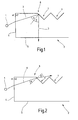
- FIG. 1 a lamp 1 and a light guide 2 is shown.
- An arrow 3 shows the course of a light beam. This passes from a medium with the refractive index n1 via an end face 4 of the light guide 2, which serves as a light coupling surface, into the light guide 2 with the refractive index n2.
- the light beam is deflected at the transition.
- the light guide 2 has a light exit surface 5 and, opposite this, a surface 6 on which prisms 7 are arranged.
- the prisms 7 are mirrored, so that the light beam is reflected and coupled out of the light guide 2 at the light exit surface 5.
- ⁇ ⁇
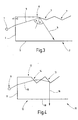
- Figure 2 illustrates what happens when the Light guide 2 the prisms are not mirrored.
- the direction of the light beam is shown with the help of an arrow 8 shown. It can be seen that without a mirror the light beam immediately hits the light guide 2 on the surface 6 would leave and not at the light exit surface 5 would decouple.
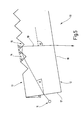
- FIG. 3 shows how total reflection of the light beam is achieved by a flatter angle of the prisms 7 in the conventional light guide 2.
- An arrow 9 shows the course of the light beam. Since the critical angle is exceeded when the light beam is incident, it is totally reflected on the prism 7. However, this means that the light beam on the opposite side, the light exit surface 5, does not leave the light guide 2 at all or at least not at the desired angle.
- the following applies: for is ⁇ ⁇
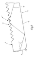
- FIG. 4 shows a signal light 10 according to the invention shown.
- This has a lamp 11 and one Light guide 12 on.
- a first prism 14 and a second prism 15 arranged on a surface 13 of the light guide 12 .
- the course of a light beam is with a Arrow 16 shown.
- the light beam comes from that Illuminant 11 through an end face 17 of the light guide 12 in this.
- the angle of the first prism 14 is like this chosen that the light beam for a certain distance decouples from the light guide 12 to at one of the the next areas. This will make the Direction of the light beam within the light guide 12 corrected.
- the light beam has on the second prism 15 an angle of incidence that a total reflection in the desired exit direction allowed.
- the beam of light couples out at the light exit surface 18.
- angles of the two prisms 14, 15 are selected so that no total reflection takes place with the first prism 14. Total reflection only occurs on the second prism 15. This is expressed mathematically by the following constraints:
- the light guide 12 is with another Light beam (arrow 19 ') shown. That beam of light is such in the prism 14 on a first surface 20 corrected that after re-entering the No light guide over a second surface 21 of the prism 14 meets the next prism but towards the Light exit surface 18 is directed. There the Light beam reflects and reaches prism 14 'in one rear section of the light guide 12. The light beam passes through this prism 14 'as described for FIG and then hits the light exit surface 18 through which he steps through. By the appropriate position of the surfaces 20 and 21 of prism 14, the light beam is in the rear Areas of the light guide 12 are directed.
- the light beam does not just cross Prism but two successive prisms.
Landscapes
- Engineering & Computer Science (AREA)
- General Engineering & Computer Science (AREA)
- Physics & Mathematics (AREA)
- Optics & Photonics (AREA)
- Microelectronics & Electronic Packaging (AREA)
- General Physics & Mathematics (AREA)
- Non-Portable Lighting Devices Or Systems Thereof (AREA)
- Optical Elements Other Than Lenses (AREA)
- Planar Illumination Modules (AREA)
- Light Guides In General And Applications Therefor (AREA)
- Optical Couplings Of Light Guides (AREA)
Applications Claiming Priority (2)
| Application Number | Priority Date | Filing Date | Title |
|---|---|---|---|
| DE10018284 | 2000-04-13 | ||
| DE10018284A DE10018284A1 (de) | 2000-04-13 | 2000-04-13 | Signalleuchte mit mindestens einem Leuchtmittel und einem Lichtleiter |
Publications (3)
| Publication Number | Publication Date |
|---|---|
| EP1146281A2 true EP1146281A2 (fr) | 2001-10-17 |
| EP1146281A3 EP1146281A3 (fr) | 2004-03-31 |
| EP1146281B1 EP1146281B1 (fr) | 2008-04-23 |
Family
ID=7638575
Family Applications (1)
| Application Number | Title | Priority Date | Filing Date |
|---|---|---|---|
| EP01102107A Expired - Lifetime EP1146281B1 (fr) | 2000-04-13 | 2001-01-31 | Lampe de signalisation avec au moins une source lumineuse et un guide de lumière |
Country Status (2)
| Country | Link |
|---|---|
| EP (1) | EP1146281B1 (fr) |
| DE (2) | DE10018284A1 (fr) |
Cited By (6)
| Publication number | Priority date | Publication date | Assignee | Title |
|---|---|---|---|---|
| EP1154197A2 (fr) | 2000-05-10 | 2001-11-14 | Hella KG Hueck & Co. | Guide de lumière en forme de barre |
| WO2005035308A1 (fr) * | 2003-10-18 | 2005-04-21 | Daimlerchrysler Ag | Dispositif d'eclairage pour un vehicule a moteur |
| US8333493B2 (en) | 2009-04-03 | 2012-12-18 | North American Lighting, Inc. | Dual-direction light pipe for automotive lighting |
| EP3413105A1 (fr) * | 2017-06-07 | 2018-12-12 | Valeo Iluminacion | Dispositif d'éclairage |
| FR3090074A1 (fr) | 2018-12-18 | 2020-06-19 | Valeo Vision | Guide de lumiere pour un module lumineux d’un vehicule automobile |
| EP3795895A1 (fr) * | 2019-09-20 | 2021-03-24 | ewo GmbH | Unité d'extraction de lumière modulaire pour la production d'une luminosité uniforme |
Families Citing this family (5)
| Publication number | Priority date | Publication date | Assignee | Title |
|---|---|---|---|---|
| DE10231326A1 (de) * | 2002-07-11 | 2004-02-19 | Hella Kg Hueck & Co. | Leuchteinheit für Fahrzeuge |
| DE20306739U1 (de) | 2003-04-30 | 2003-08-07 | Fer Fahrzeugelek K Gmbh | Fahrzeugleuchte |
| DE102008034052B4 (de) * | 2008-07-22 | 2019-08-14 | HELLA GmbH & Co. KGaA | Lichtleitkörper zur Anwendung als Positionslicht oder als Tagfahrlicht für ein Kraftfahrzeug |
| DE102009010507A1 (de) | 2009-02-25 | 2010-08-26 | Daimler Ag | Beleuchtungseinrichtung für ein Kraftfahrzeug |
| DE202016105104U1 (de) * | 2016-09-14 | 2017-12-15 | Zumtobel Lighting Gmbh | Anordnung zur Lichtabgabe |
Citations (2)
| Publication number | Priority date | Publication date | Assignee | Title |
|---|---|---|---|---|
| DE4129094A1 (de) | 1991-09-02 | 1993-03-04 | Hella Kg Hueck & Co | Signalleuchte fuer kraftfahrzeuge |
| EP0933587A2 (fr) | 1998-01-30 | 1999-08-04 | Hella KG Hueck & Co. | Guide de lumière en forme de barre |
Family Cites Families (6)
| Publication number | Priority date | Publication date | Assignee | Title |
|---|---|---|---|---|
| JPH0642028B2 (ja) * | 1983-06-07 | 1994-06-01 | セイコーエプソン株式会社 | 平面光源 |
| DE4212892C2 (de) * | 1992-04-17 | 1995-07-13 | Reitter & Schefenacker Gmbh | Linsensystem für eine Lichtscheibe einer Kraftfahrzeugheckleuchte |
| US5521725A (en) * | 1993-11-05 | 1996-05-28 | Alliedsignal Inc. | Illumination system employing an array of microprisms |
| US6072551A (en) * | 1996-02-14 | 2000-06-06 | Physical Optics Corporation | Backlight apparatus for illuminating a display with controlled light output characteristics |
| DE19803537A1 (de) * | 1998-01-30 | 1999-08-05 | Hella Kg Hueck & Co | Leuchte für Fahrzeuge |
| DE19806526A1 (de) * | 1998-02-17 | 1999-08-19 | Hella Kg Hueck & Co | Beleuchtungseinrichtung für Kraftfahrzeuge |
-
2000
- 2000-04-13 DE DE10018284A patent/DE10018284A1/de not_active Ceased
-
2001
- 2001-01-31 EP EP01102107A patent/EP1146281B1/fr not_active Expired - Lifetime
- 2001-01-31 DE DE50113875T patent/DE50113875D1/de not_active Expired - Lifetime
Patent Citations (2)
| Publication number | Priority date | Publication date | Assignee | Title |
|---|---|---|---|---|
| DE4129094A1 (de) | 1991-09-02 | 1993-03-04 | Hella Kg Hueck & Co | Signalleuchte fuer kraftfahrzeuge |
| EP0933587A2 (fr) | 1998-01-30 | 1999-08-04 | Hella KG Hueck & Co. | Guide de lumière en forme de barre |
Cited By (7)
| Publication number | Priority date | Publication date | Assignee | Title |
|---|---|---|---|---|
| EP1154197A2 (fr) | 2000-05-10 | 2001-11-14 | Hella KG Hueck & Co. | Guide de lumière en forme de barre |
| EP1154197A3 (fr) * | 2000-05-10 | 2004-05-12 | Hella KG Hueck & Co. | Guide de lumière en forme de barre |
| WO2005035308A1 (fr) * | 2003-10-18 | 2005-04-21 | Daimlerchrysler Ag | Dispositif d'eclairage pour un vehicule a moteur |
| US8333493B2 (en) | 2009-04-03 | 2012-12-18 | North American Lighting, Inc. | Dual-direction light pipe for automotive lighting |
| EP3413105A1 (fr) * | 2017-06-07 | 2018-12-12 | Valeo Iluminacion | Dispositif d'éclairage |
| FR3090074A1 (fr) | 2018-12-18 | 2020-06-19 | Valeo Vision | Guide de lumiere pour un module lumineux d’un vehicule automobile |
| EP3795895A1 (fr) * | 2019-09-20 | 2021-03-24 | ewo GmbH | Unité d'extraction de lumière modulaire pour la production d'une luminosité uniforme |
Also Published As
| Publication number | Publication date |
|---|---|
| DE50113875D1 (de) | 2008-06-05 |
| DE10018284A1 (de) | 2001-10-18 |
| EP1146281B1 (fr) | 2008-04-23 |
| EP1146281A3 (fr) | 2004-03-31 |
Similar Documents
| Publication | Publication Date | Title |
|---|---|---|
| DE19746025B4 (de) | Beleuchtungsanordnung eines Fahrzeugs | |
| EP0933587B1 (fr) | Guide de lumière en forme de barre | |
| DE10234110B4 (de) | Leuchte für Fahrzeuge, insbesondere Kraftfahrzeuge | |
| EP2502784B1 (fr) | Lampe de véhicule, en particulier pour éclairer l'intérieur du véhicule | |
| EP0944799A1 (fr) | Unite d'eclairage | |
| WO2016070210A1 (fr) | Système d'éclairage pour véhicule à moteur | |
| DE102007023076B4 (de) | Beleuchtungseinrichtung für Kraftfahrzeuge | |
| EP1146281A2 (fr) | Lampe de signalisation avec au moins une source lumineuse et un guide de lumière | |
| EP0933588A2 (fr) | Feu pour véhicule | |
| DE20206829U1 (de) | Leuchte, insbesondere Begrenzungsleuchte | |
| EP2500753B1 (fr) | Conducteur lumineux doté d'éléments de déclenchement déclenchés à lumière directe | |
| DE69707078T2 (de) | Kraftfahrzeug- Scheinwerfer mit einem Lichtleiter | |
| EP0936403B1 (fr) | Dispositif d'éclairage pour des véhicules automobiles. | |
| DE102006037797B4 (de) | Kraftfahrzeugleuchte | |
| DE102011090197B4 (de) | Lichtleiter für eine Kraftfahrzeugbeleuchtungseinrichtung | |
| EP2927572A1 (fr) | Lampe de véhicule automobile avec effet d'essuyage | |
| EP1154198A2 (fr) | Guide de lumière en forme de barre | |
| DE102005011760A1 (de) | Scheinwerfereinrichtung für Kraftfahrzeuge | |
| EP3812653B1 (fr) | Feu de signalisation pourvu de guide de lumière | |
| DE10317062A1 (de) | Beleuchtungseinrichtung für Kraftfahrzeuge | |
| DE102005059958A1 (de) | Beleuchtungseinrichtung | |
| DE102012213547B4 (de) | Beleuchtungseinrichtung für ein Kraftfahrzeug | |
| DE102017106441A1 (de) | Kraftfahrzeugleuchte mit einem flächigen Lichtleiter | |
| EP1686398B1 (fr) | Capteur optoélectronique | |
| DE19838221A1 (de) | Beleuchtungs- oder Signaleinrichtung mit optischem Lichtleiter, insbesondere für Kraftfahrzeuge |
Legal Events
| Date | Code | Title | Description |
|---|---|---|---|
| PUAI | Public reference made under article 153(3) epc to a published international application that has entered the european phase |
Free format text: ORIGINAL CODE: 0009012 |
|
| AK | Designated contracting states |
Kind code of ref document: A2 Designated state(s): AT BE CH CY DE DK ES FI FR GB GR IE IT LI LU MC NL PT SE TR |
|
| AX | Request for extension of the european patent |
Free format text: AL;LT;LV;MK;RO;SI |
|
| PUAL | Search report despatched |
Free format text: ORIGINAL CODE: 0009013 |
|
| AK | Designated contracting states |
Kind code of ref document: A3 Designated state(s): AT BE CH CY DE DK ES FI FR GB GR IE IT LI LU MC NL PT SE TR |
|
| AX | Request for extension of the european patent |
Extension state: AL LT LV MK RO SI |
|
| RIC1 | Information provided on ipc code assigned before grant |
Ipc: 7F 21V 8/00 B Ipc: 7F 21S 8/10 A Ipc: 7F 21W 101/14 B Ipc: 7F 21W 101/12 B |
|
| 17P | Request for examination filed |
Effective date: 20040710 |
|
| 17Q | First examination report despatched |
Effective date: 20041012 |
|
| AKX | Designation fees paid |
Designated state(s): DE ES FR GB IT |
|
| GRAP | Despatch of communication of intention to grant a patent |
Free format text: ORIGINAL CODE: EPIDOSNIGR1 |
|
| GRAS | Grant fee paid |
Free format text: ORIGINAL CODE: EPIDOSNIGR3 |
|
| GRAA | (expected) grant |
Free format text: ORIGINAL CODE: 0009210 |
|
| AK | Designated contracting states |
Kind code of ref document: B1 Designated state(s): DE ES FR GB IT |
|
| REG | Reference to a national code |
Ref country code: GB Ref legal event code: FG4D Free format text: NOT ENGLISH |
|
| REF | Corresponds to: |
Ref document number: 50113875 Country of ref document: DE Date of ref document: 20080605 Kind code of ref document: P |
|
| PG25 | Lapsed in a contracting state [announced via postgrant information from national office to epo] |
Ref country code: ES Free format text: LAPSE BECAUSE OF FAILURE TO SUBMIT A TRANSLATION OF THE DESCRIPTION OR TO PAY THE FEE WITHIN THE PRESCRIBED TIME-LIMIT Effective date: 20080803 |
|
| ET | Fr: translation filed | ||
| PLBE | No opposition filed within time limit |
Free format text: ORIGINAL CODE: 0009261 |
|
| STAA | Information on the status of an ep patent application or granted ep patent |
Free format text: STATUS: NO OPPOSITION FILED WITHIN TIME LIMIT |
|
| 26N | No opposition filed |
Effective date: 20090126 |
|
| PG25 | Lapsed in a contracting state [announced via postgrant information from national office to epo] |
Ref country code: IT Free format text: LAPSE BECAUSE OF FAILURE TO SUBMIT A TRANSLATION OF THE DESCRIPTION OR TO PAY THE FEE WITHIN THE PRESCRIBED TIME-LIMIT Effective date: 20080423 |
|
| GBPC | Gb: european patent ceased through non-payment of renewal fee |
Effective date: 20090131 |
|
| PG25 | Lapsed in a contracting state [announced via postgrant information from national office to epo] |
Ref country code: GB Free format text: LAPSE BECAUSE OF NON-PAYMENT OF DUE FEES Effective date: 20090131 |
|
| PGFP | Annual fee paid to national office [announced via postgrant information from national office to epo] |
Ref country code: FR Payment date: 20130225 Year of fee payment: 13 Ref country code: DE Payment date: 20130110 Year of fee payment: 13 |
|
| REG | Reference to a national code |
Ref country code: DE Ref legal event code: R119 Ref document number: 50113875 Country of ref document: DE |
|
| REG | Reference to a national code |
Ref country code: DE Ref legal event code: R119 Ref document number: 50113875 Country of ref document: DE Effective date: 20140801 |
|
| PG25 | Lapsed in a contracting state [announced via postgrant information from national office to epo] |
Ref country code: DE Free format text: LAPSE BECAUSE OF NON-PAYMENT OF DUE FEES Effective date: 20140801 |
|
| REG | Reference to a national code |
Ref country code: FR Ref legal event code: ST Effective date: 20140930 |
|
| PG25 | Lapsed in a contracting state [announced via postgrant information from national office to epo] |
Ref country code: FR Free format text: LAPSE BECAUSE OF NON-PAYMENT OF DUE FEES Effective date: 20140131 |