EP1146347B1 - Détection de particules magnétiques - Google Patents
Détection de particules magnétiques Download PDFInfo
- Publication number
- EP1146347B1 EP1146347B1 EP20010303319 EP01303319A EP1146347B1 EP 1146347 B1 EP1146347 B1 EP 1146347B1 EP 20010303319 EP20010303319 EP 20010303319 EP 01303319 A EP01303319 A EP 01303319A EP 1146347 B1 EP1146347 B1 EP 1146347B1
- Authority
- EP
- European Patent Office
- Prior art keywords
- coil
- sample
- tuned circuit
- resonant frequency
- magnetic field
- Prior art date
- Legal status (The legal status is an assumption and is not a legal conclusion. Google has not performed a legal analysis and makes no representation as to the accuracy of the status listed.)
- Expired - Lifetime
Links
- 239000006249 magnetic particle Substances 0.000 title claims description 34
- 238000001514 detection method Methods 0.000 title description 2
- 238000000034 method Methods 0.000 claims description 49
- 230000005291 magnetic effect Effects 0.000 claims description 29
- 239000000758 substrate Substances 0.000 claims description 25
- 239000004033 plastic Substances 0.000 claims description 21
- 238000003018 immunoassay Methods 0.000 claims description 13
- 239000003990 capacitor Substances 0.000 claims description 10
- 239000000427 antigen Substances 0.000 claims description 7
- 102000036639 antigens Human genes 0.000 claims description 7
- 108091007433 antigens Proteins 0.000 claims description 7
- 239000002052 molecular layer Substances 0.000 claims description 4
- 238000000159 protein binding assay Methods 0.000 claims description 4
- 208000006930 Pseudomyxoma Peritonei Diseases 0.000 claims 2
- 229920000306 polymethylpentene Polymers 0.000 claims 2
- 230000001419 dependent effect Effects 0.000 claims 1
- 239000002245 particle Substances 0.000 description 51
- 239000012071 phase Substances 0.000 description 23
- 230000008859 change Effects 0.000 description 17
- 230000035699 permeability Effects 0.000 description 14
- 238000012360 testing method Methods 0.000 description 13
- 230000005298 paramagnetic effect Effects 0.000 description 12
- 230000000694 effects Effects 0.000 description 10
- 238000005259 measurement Methods 0.000 description 9
- 230000010355 oscillation Effects 0.000 description 9
- 230000035945 sensitivity Effects 0.000 description 9
- 238000010586 diagram Methods 0.000 description 8
- 238000003556 assay Methods 0.000 description 7
- 238000010276 construction Methods 0.000 description 7
- 230000004044 response Effects 0.000 description 7
- 229910000859 α-Fe Inorganic materials 0.000 description 6
- 239000007853 buffer solution Substances 0.000 description 5
- 230000007423 decrease Effects 0.000 description 5
- RYGMFSIKBFXOCR-UHFFFAOYSA-N Copper Chemical compound [Cu] RYGMFSIKBFXOCR-UHFFFAOYSA-N 0.000 description 4
- 238000002474 experimental method Methods 0.000 description 4
- 230000005294 ferromagnetic effect Effects 0.000 description 4
- 230000001965 increasing effect Effects 0.000 description 4
- 230000007774 longterm Effects 0.000 description 4
- 238000004804 winding Methods 0.000 description 4
- 229920003319 Araldite® Polymers 0.000 description 3
- 102000004338 Transferrin Human genes 0.000 description 3
- 108090000901 Transferrin Proteins 0.000 description 3
- 239000000872 buffer Substances 0.000 description 3
- 238000013461 design Methods 0.000 description 3
- 230000008105 immune reaction Effects 0.000 description 3
- 239000000463 material Substances 0.000 description 3
- 239000004810 polytetrafluoroethylene Substances 0.000 description 3
- 229920001343 polytetrafluoroethylene Polymers 0.000 description 3
- 230000008569 process Effects 0.000 description 3
- 239000000126 substance Substances 0.000 description 3
- 239000000725 suspension Substances 0.000 description 3
- 239000012581 transferrin Substances 0.000 description 3
- 238000005406 washing Methods 0.000 description 3
- 238000013459 approach Methods 0.000 description 2
- 230000008901 benefit Effects 0.000 description 2
- 239000004020 conductor Substances 0.000 description 2
- 230000003247 decreasing effect Effects 0.000 description 2
- 238000011161 development Methods 0.000 description 2
- 231100000673 dose–response relationship Toxicity 0.000 description 2
- 230000005672 electromagnetic field Effects 0.000 description 2
- 239000007790 solid phase Substances 0.000 description 2
- 102000004190 Enzymes Human genes 0.000 description 1
- 108090000790 Enzymes Proteins 0.000 description 1
- 239000003082 abrasive agent Substances 0.000 description 1
- 239000012062 aqueous buffer Substances 0.000 description 1
- 238000011953 bioanalysis Methods 0.000 description 1
- 238000005119 centrifugation Methods 0.000 description 1
- 239000011248 coating agent Substances 0.000 description 1
- 238000000576 coating method Methods 0.000 description 1
- 230000000052 comparative effect Effects 0.000 description 1
- 239000004035 construction material Substances 0.000 description 1
- 238000005516 engineering process Methods 0.000 description 1
- 230000008713 feedback mechanism Effects 0.000 description 1
- 238000001914 filtration Methods 0.000 description 1
- 239000011521 glass Substances 0.000 description 1
- 238000009396 hybridization Methods 0.000 description 1
- 230000001939 inductive effect Effects 0.000 description 1
- 238000011835 investigation Methods 0.000 description 1
- 238000012417 linear regression Methods 0.000 description 1
- 238000004519 manufacturing process Methods 0.000 description 1
- 239000007769 metal material Substances 0.000 description 1
- 238000002156 mixing Methods 0.000 description 1
- 239000000203 mixture Substances 0.000 description 1
- 238000012544 monitoring process Methods 0.000 description 1
- 239000000615 nonconductor Substances 0.000 description 1
- 238000011017 operating method Methods 0.000 description 1
- 239000002907 paramagnetic material Substances 0.000 description 1
- 239000002985 plastic film Substances 0.000 description 1
- 229920006255 plastic film Polymers 0.000 description 1
- 229920000642 polymer Polymers 0.000 description 1
- 102000004169 proteins and genes Human genes 0.000 description 1
- 108090000623 proteins and genes Proteins 0.000 description 1
- 238000000746 purification Methods 0.000 description 1
- 230000002285 radioactive effect Effects 0.000 description 1
- 238000000926 separation method Methods 0.000 description 1
- 239000000243 solution Substances 0.000 description 1
- XLYOFNOQVPJJNP-UHFFFAOYSA-N water Substances O XLYOFNOQVPJJNP-UHFFFAOYSA-N 0.000 description 1
Images


Classifications
-
- G—PHYSICS
- G01—MEASURING; TESTING
- G01R—MEASURING ELECTRIC VARIABLES; MEASURING MAGNETIC VARIABLES
- G01R33/00—Arrangements or instruments for measuring magnetic variables
- G01R33/12—Measuring magnetic properties of articles or specimens of solids or fluids
- G01R33/1223—Measuring permeability, i.e. permeameters
Definitions
- the present invention relates to a method and apparatus for determining the number of magnetic particles within a sample, for example a method of determining the number of magnetic particles when performing an immunoassay.
- the technique allows coated paramagnetic particles (PMP's) to be used as labels and to detect them using a novel electronic circuitry design.
- the PMP's are typically 2.8 ⁇ m in diameter and consist of a core of a paramagnetic material coated with a suitable polymer layer to which are attached antibody/antigen layers depending on the particular application of the PMP.
- a suitable polymer layer to which are attached antibody/antigen layers depending on the particular application of the PMP.
- the main application of these particles is in sample separation, purification and as a solid phase for immunoassays.
- the PMP's are coated with proteins allowing them to be used as the solid phase material on which an immune reaction takes place.
- the immune reaction is detected and quantified using a label such as an enzyme, fluorescent or chemiluminescent molecule.
- the PMP's are not permanently magnetised but are attracted to permanent magnets allowing simple washing procedures, therefore washing the coated PMP's does not require filtration or centrifugation. Following the washing steps, the immobilized label on the surface of the coated PMP's is detected using a suitable technique.
- US-A-5978694 describes a method and apparatus for detecting in a sample a substance which responds to an applied magnetic field, such as a paramagnetic substance. The detection is achieved by placing the sample in an applied, external magnetic field and determining the effect of the sample on the performance of a characteristic such as resistance, conductance, inductance, capacitance, and efficiency of the conductor. This is a complex device requiring a permanent magnet or electromagnet to provide the external magnetic field and is not intended to determine the number of particles within the sample.
- US-A-5922537 describes the use of paramagnetic particles which selectively bind to a surface to affect the magnetic properties of the surface.
- US-A-4940939 describes a system for checking the composition of non-metallic materials, for example in the manufacture of abrasive materials, construction materials etc and utilizes a pair of LC oscillator circuits and determines the difference in phase between the two circuits one of which has a loop position near the (magnetic) sample.
- US-A-5528142 describes a method for quantifying the permeability of conductivity of a conducting material using an inductive circuit and monitoring a frequency difference.
- the present invention provides a method and apparatus for determining the number of magnetic particles within a sample.
- the present invention utilizes the fact that the presence of magnetic particles, such as paramagnetic, ferromagnetic particles, or the like will lead to an inherent change in the permeability of the sample. Because the self-inductance of a coil depends on the permeability of the material within the coil, placing a sample containing magnetic particles in a coil will result in a change in the inductance of the coil.
- the present invention utilizes this effect by obtaining an indication of the inductance of the coil by measuring the resonant frequency of an LC circuit including the coil. The resonant frequency of the circuit will be different when the sample is placed within the coil compared to when the sample is removed from the coil.
- the coil by measuring the change in the resonant frequency of the LC circuit, it is possible to determine the number of magnetic particles within the sample. Furthermore, by selecting the coil to be one of a solenoid, a ring coil and a flat coil, this helps minimize the dead space between the coil and the sample, thereby ensuring that an optimum signal is obtained.
- the step of determining the difference in the resonant frequency of the tuned circuit comprises placing the sample within the coil; determining the resonant frequency of the tuned circuit; removing the sample from the coil; and, determining the resonant frequency of the tuned circuit. It is preferred to determine the resonant frequency of the tuned circuit with the sample present and then with the sample removed to account for long term variation in the resonant frequency of the coil. These long term variations are typically caused by variations in temperature within the surrounding environment, and other such factors. However, as these variations are typically long term occurring over several hours, then by making subsequent measurements with the sample present and then shortly afterwards with the sample removed, this ensures that any variation in the measured resonant frequency is solely due to the presence and/or absence of the sample.
- the step of determining the resonant frequency comprises applying the driver signal to the tuned circuit; measuring the phase difference between the driver signal and the output signal taken from the tuned circuit; and adjusting the frequency of the applied signal until there is no phase difference between the applied signal and the output signal.
- Other suitable methods may be used but this advantageously allows the circuit to be adjusted using a feedback mechanism so that the circuit automatically locates the resonant frequency.
- the driver signal usually has a frequency of above 200kHz and more particularly preferably has a frequency above 500kHz. This is because at higher frequencies a given change in the inductance of a coil will result in a larger change in the resonant frequency of the tuned circuit. Accordingly, operating the circuit at a higher frequency increases the sensitivity of the system.
- the magnetic particles used are paramagnetic particles although ferromagnetic or any other magnetic particles may also be used.
- the detector for detecting the resonant frequency of the tuned circuit may comprise a phase comparator, for determining the phase difference between the driver signal and an output signal obtained from the tuned circuit, whilst the driver for applying the driver signal to the circuit comprises a voltage controlled oscillator (VCO).
- VCO voltage controlled oscillator
- the apparatus comprises a phase locked loop oscillator circuit. This is particularly advantageous because as mentioned above, this allows the resonant frequency of the tuned circuit to be accurately determined without human intervention. This is an automatic procedure resulting in highly accurate results.
- the invention is particularly suited for use during an immunoassay. However, it is also applicable for use with other types of samples such as bottles and other containers, labels etc.
- the present invention also provides a method of performing an assay using magnetic particles as labels. This is achieved using a substrate to which has been immobilized a layer of molecules appropriate to the assay.
- the reaction is designed in such a way that bonds form between the coating on the magnetic particle and the immobilized layer on the substrate.
- the number of particles bonding to the substrate depends on the concentration of species being measured. Accordingly, by measuring the change in the resonant frequency of the tuned circuit when the substrate is contained within, and when the substrate is not contained within the coil, allows the number of magnetic particles bound to the substrate to be determined.
- the magnetic particles are bound to a respective number of second molecules and wherein the reaction binds the second molecules with the layer of molecules so as to bind the magnetic particles to the substrate.
- the magnetic particles may be designed to react directly with the molecules bound to the substrate.
- the reaction may be any form of reaction, such as a DNA hybridization reaction.
- the first and second molecules would comprise portions of DNA.
- the binding assay is an immunoassay in which case the molecule layer is an antibody/antigen layer and the second molecules are antigens or antibodies. Accordingly, the magnetic particles can be coupled to the antigens or antibodies which then bind to the antibody/antigen layer formed on the substrate.
- the tuned circuit is one of a solenoid, a ring coil and a flat coil.
- the method typically involves exposing the sample to the magnetic field by placing it in the coil.
- the coil preferably has an oval cross-section, although a rectangular cross-section can be used.
- flat coils may be used with the sample being exposed to the magnetic field by placing the sample adjacent the coil.
- the third aspect of the present invention can advantageously be implemented using the first and second aspects of the present invention.
- the above described electronic circuitry can be used to generate an output directly related to the number of immobilized PMP's on the strip.
- the PMP particles are now being used as markers and separate fluorescent, radioactive, chemiluminescent or other markers are not required. This considerably reduces the number of analytical steps and speeds up the time required for an assay.
- the electronic circuitry is physically small enough to allow the development of a hand-held instrument.
- the number of coated paramagnetic particles on a plastic strip is determined by placing the strip in a coil of insulated wire and observing the effect their presence has on the self-inductance, L, of the coil. The assumption is that the only significant contribution to changes in the inductance of the coil comes from the high magnetic permeability of the particles.
- the effective value of ⁇ for the coil is some value related to the individual permeabilities of the plastic in the strip ⁇ v , any residual buffer solution on the plastic strip ⁇ s , the particles ⁇ p , and the air space in the coil ⁇ A .
- the magnetic field surrounding each particle is non-uniform, but since the particles are all the same shape and size (2.8 ⁇ m diameter) they contribute equally to the total effective permeability.
- the plastic strips were of identical construction and the volume of the buffer solution residue may be assumed to be constant.
- the inductance of the coil therefore increases uniformly with the number of particles on the strip.
- L 0 should be as small as possible and k as large as possible. Keeping the dead space in the coil to a minimum by decreasing the internal dimensions of the coil so that they are just large enough to contain the sample strip will reduce c A and hence L 0 . This will also ensure that more of the electromagnetic field in the coil passes through the particles so increasing c and hence k.
- f ⁇ 2 ⁇ (LC) 1 ⁇ 2 ⁇ -1
- f f 0 ⁇ 1 + (k/L 0 )n ⁇ -1 ⁇ 2
- Equation (6) predicts that the frequency of oscillation of the LC-tuned circuit should decrease linearly with increasing numbers of paramagnetic particles present on the strip.
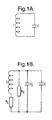
- the coil has an internal resistance R L , the capacitor a leakage resistance R C , and there is a stray capacitance C L mainly existing between individual windings in the coil.
- R C is very large and has a negligible effect on the performance of the circuit.
- the stray capacitance depends very much on the construction of the coil and reduces the resonant frequency of the circuit. If the coil has a rigid construction then C L should remain constant so its presence can be largely ignored.
- the resonant frequency of a practical LC circuit is very temperature dependant.
- the values of all of the components shown in Figure 1B vary with temperature to some extent and so contribute to the drift in the resonant frequency with temperature.
- the coil is made from thin copper wire which increases in resistance with temperature. Additionally, the dimensions of the coil and the capacitance of the capacitor C also change with temperature.
- the frequency of oscillation of a LC circuit is determined by using the LC circuit to control the frequency of oscillation of an oscillator circuit.
- Experimentation showed that typically the resonant frequency decreases by only a few Hz when a plastic strip with particles on it is placed in a coil oscillating at about 250 kHz.
- the oscillator circuit therefore has to be very stable.
- the circuit shown in Figure 3 comprises a voltage controlled oscillator (VCO) 1 whose output is coupled to a frequency meter 2 and a phase detector 3.
- the output of the voltage controlled oscillator 1 is also coupled via a resistor 5 to a tuned LC circuit 4 which includes a coil L and a capacitor C, as shown.
- the phase detector 3, as well as being coupled to the output of the VCO 1 is also coupled to the tuned circuit 4.
- the output of a phase detector 3 is transferred via a loop filter 6 to the VCO 1.
- the VCO 1 is used to generate a drive signal which is applied to the tuned circuit 4 via the resistor 5, which causes the tuned circuit 4 to oscillate.
- the phase detector 3 is coupled to the output of the VCO 1 so as to determine the phase of the driver signal, and to the tuned circuit 4 to determine the phase of the oscillation of the tuned circuit.
- the phase detector 3 then generates a DC signal representative of the difference in the phases of oscillation which is output to the loop filter 6.
- the loop filter filters the signal which is then returned to the voltage controlled oscillator 1.
- the VCO 1 is controlled such that upon the application of the DC error signal, it will change its output frequency until no phase difference exists between the drive signal and the oscillation of the tuned circuit and accordingly no error signal is output from the phase detector 3.
- the output frequency of the VCO is measured on the frequency meter.
- This circuit gives a considerably improved frequency stability and frequency changes of less than 1 Hz in the resonance frequency of 200 to 300 kHz can be measured.
- IC1 is a VCO with a sine wave output which can be varied over the range from about 18k ⁇ to 38k ⁇ using the 10k ⁇ preset.
- the output of the VCO is fed to the LC circuit via a 10k ⁇ resistor.
- OP1 is a comparator which derives a square wave from the sinusoidal wave at the output of the VCO and drives IC2, a D-type flip-flop.
- the sinewave voltage across the LC circuit is transferred via a high-input impedance buffer amplifier (OP2) to a second comparator (OP3) and flip-flop (IC3).
- the flip-flops in conjunction with the NAND gates (IC4) and the diodes D1 and D4, form an edge-sensitive lead-lag (type II) phase sensitive detector.
- OP4 a high-gain, low-pass, filter
- the error signal is limited to about ⁇ 0.6 V by diodes D3 and D4.
- the loop is closed by feeding back the dc error signal to the VCO via a buffer amplifier (OP5).
- the performance of the PLL circuit shown in Figure 3 was initially investigated using samples containing relatively large numbers of PMP's in suspension.
- the samples with known concentrations of PMP's suspended in buffer solutions (0, 1.03, 2.11, 4.19, 6.22 and 8.21 mg/ml) were used.
- the samples were contained in sealed, cylindrical, plastic vials, 30 mm in diameter and 47mm high.
- the vials contained 20 mls of suspension.
- the vials were shaken vigorously to ensure a uniform mixing and then placed in the coil (50 turns of 24 SWG enamelled copper wire, inductance ⁇ 75 ⁇ H) attached to the phase-locked-loop circuit ( Figure 5) and the frequency of oscillation measured.
- the sample vial was now removed and the increase in frequency noted.
- the experiment was repeated 10 times for all the vials and the difference in the two readings was plotted against the concentration of particles in the vials, as shown in Figure 4.
- the system can be used for carrying out measurements of a number of PMPs bonded to a substrate, as occurs for example in the immunoassay process.
- Calibration of the system was then performed by producing a number of substrates, which in this case were plastic strips such as those that would be used in an immunoassay process, with known numbers of PMPs thereon. These were then used to determine the frequency change obtained for a given number of particles.
- the particles used were Dynal M-230 which have diameters of 2.8 ⁇ m.
- the concentration of particles in a sample was determined by counting the number of particles in a known volume. This was achieved using a New Neubauer haemocytometer, which has calibrated squares etched into a glass slide and a known depth. Knowing the concentration, the number of particles applied to the plastic strip was calculated. The particles were dried onto the plastic strips. Several standards with numbers of particles ranging from 3.33 x 10 6 to 1.68 x 10 5 were made and these were used to calibrate the response of the instrument.
- the response of the PLL circuit of Figure 3 to the standard plastic strips using a basic coil configuration was determined.
- the method used was as described previously.
- a test strip with a known number of PMP's on it was inserted into the coil L and the resonant frequency of the tuned circuit 4 measured.
- the sample was then removed from the coil L and the resonant frequency again measured.
- the change in the reasonant frequency was noted.
- the experiment was repeated ten times using the same test strip.
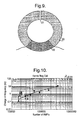
- the experiment was repeated using the other test strips. The results are shown on a graph of the number of PMPs against the change in resonant frequency as in Figure 6.
- the results are plotted on log - log axes with a best straight line being determined using a linear regression.
- the points show the mean value of the readings for each sample and the error bars are the standard errors of the mean.
- the PLL circuit has a good linear response to the increasing number of particles on the test strips as predicted by equation (6) with a sensitivity of about 0.16 Hz/10 5 particles.
- the optimum coil is a solenoidal coil having an oval cross-sectional shape into which the sample substrates used in the immunoassay procedure just fit.
- the inductance of a coil increases with the effective cross-sectional area of the coil and the number of turns in the coil. Decreasing the cross-sectional area of the coil means that the number of turns in the coil has to increase to produce a coil with the required inductance. Accordingly, the length of the coil is preferably made just slightly larger than the length of the sample. This means that the wire has to be very thin, otherwise a very thick, multilayered, coil is produced.
- a coil L as shown in Figure 7, was produced made with an oval cross-section of 2.5 x 7 mm and 7 mm long.
- This coil arrangement when used with the PLL circuit also had a good linear response with an improve sensitivity compared with the previous coil design of about 0.4Hz/10 5 particles on the test strip.
- the error bars were also smaller showing that the circuit was generally more stable.
- the sensitivity of this coil arrangement could be improved further by making the coil smaller so that there is even less dead space between the coil and the sample. Smaller coils would require even thinner wire than the 42 SWG used in this construction. Winding coils accurately by hand is difficult with such thin wire so some sort of machine winding would be necessary.
- FIG. 9 A further development to the coil construction is shown in Figure 9.
- This comprises a ferrite ring 20 around which is wound a winding 22.
- Ferrites are electrical insulators which can have very high magnetic permeabilities and which can operate at very high frequencies. This means that a coil with a ferrite core requires a relatively small number of turns to have a high inductance.
- the ferrite ring 20 includes a gap 21 which has a thickness of about 1mm.
- the gap between the two ends of the ferrite is small so that little of the electromagnetic field produced by the coil is lost and it passes through a sample strip placed in the slot.
- the presence of paramagnetic particles in the sample will increase the inductance of the coil and accordingly this configuration can be used as the coil L in the tuned circuit 4.
- a totally flat coil based on a circular or square spiral arrangement ( Figures 11A and 11B) can also be used.
- This design has several advantages over previously described arrangements.
- the coil can be placed in close contact with the sample, thus reducing the dead space between the sample and the coil, and reproducible coils could be mass produced using a photo-lithographic or similar technique. If two coils are connected in series and placed facing each other with the sample between them, then the presence of paramagnetic particles in the sample would increase the inductance of the pair.
- the coils were generally operated at frequencies between about 200 to 300kHz. This was found by experiment to be the best operating frequency range when the circuit was used with vials containing large numbers of PMP's suspended in aqueous buffer solutions. However, the presence of the water makes the circuits less stable when operated at higher frequencies.
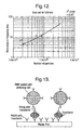
- Figure 12 shows the response of the circuit with the oval coil operating at 529kHz.
- the sensitivity is increased to 1.2 Hz/10 5 particles compared with 0.4 Hz/10 5 particles when the coil was operated at 217 kHz.
- the general technique would demonstrate improved sensitivity at even higher frequencies.
- the VCO circuit of Figure 5 is unable to operate reliably at a frequencies much higher than 519kHz because of limitations in the performance of some of the components used. To get it to operate at higher frequencies, it will be necessary to modified the circuit by using components which can operate at these frequencies.
- a model assay system using PMP's as a label, was developed. This was based on a double antibody, sandwich assay for transferrin. The model assay was developed so the immune reaction occurred on the surface of a plastic film and the test area could be easily introduced onto the detector.
- the label used to detect the immobilized immune complex was a PMP coated with a suitable antibody. This is shown schematically in Figure 13.
- the concentration of the different antibody layers was optimised to give maximum response over the working transferrin concentration range.
- a dose response curve was generated for the model assay, the numbers of particles being quantified both by manual counting using a microscope and using the detector.
Landscapes
- Physics & Mathematics (AREA)
- Condensed Matter Physics & Semiconductors (AREA)
- General Physics & Mathematics (AREA)
- Investigating Or Analyzing Materials By The Use Of Magnetic Means (AREA)
Claims (27)
- Procédé pour déterminer le nombre de particules magnétiques à l'intérieur d'un échantillon en utilisant un circuit à amplification directe comprenant un condensateur (C) et une bobine (L), le procédé comprenant:(a) la détermination de la différence de fréquence de résonance du circuit à amplification directe lorsque l'échantillon est exposé à un champ magnétique généré par la bobine (L) et lorsque l'échantillon n'est pas exposé au champ magnétique généré par la bobine (L) ; et(b) l'utilisation de la différence de fréquence de résonance pour déterminer le nombre de particules magnétiques à l'intérieur de l'échantillon.
- Procédé selon la revendication 1, dans lequel l'étape (a) comprend:i. l'exposition de l'échantillon au champ magnétique généré par la bobine (L) ;ii. la détermination de la fréquence de résonance du circuit à amplification directe ;iii. l'enlèvement de l'échantillon hors du champ magnétique généré par la bobine (L) ; etiv. la détermination de la fréquence de résonance du circuit à amplification directe.
- Procédé selon la revendication 2, dans lequel l'étape de détermination de la fréquence de résonance comprend :(a) l'application d'un signal de commande au circuit à amplification directe;(b) la mesure de la différence de phase entre le signal de commande et un signal de sortie émis par le circuit à amplification directe ; et(c) le réglage de la fréquence du signal appliqué jusqu'à ce qu'il n'y ait plus de différence de phase entre le signal appliqué et le signal de sortie.
- Procédé selon la revendication 3, dans lequel la fréquence du signal de commande est supérieure à 200 kHz.
- Procédé selon l'une quelconque des revendications précédentes, dans lequel les particules magnétiques comprennent des PMP.
- Procédé selon l'une quelconque des revendications précédentes, dans lequel la bobine (L) est soit une bobine de solénoïde, soit une bobine annulaire, soit une bobine plate.
- Procédé selon la revendication 6, dans lequel, lorsque la bobine (L) est une bobine de solénoïde, l'étape d'exposition de l'échantillon au champ magnétique comprend la mise en place de l'échantillon à l'intérieur de la bobine de solénoïde.
- Procédé selon la revendication 6, dans lequel, lorsque la bobine (L) est une bobine plate, le procédé comprend la mise en place de l'échantillon à proximité de la bobine.
- Procédé pour réaliser un test de liaison, le procédé comprenant(a) l'immobilisation d'une couche de molécules sur un substrat ;(b) la fourniture d'un certain nombre de particules magnétiques sous la forme d'étiquettes ;(c) l'exécution d'une réaction en utilisant la couche moléculaire de manière à lier au moins quelques-unes des particules magnétiques au substrat ; et(d) la détermination du nombre de particules magnétiques liées au substrat en déterminant la différence de fréquence de résonance d'un circuit à amplification directe lorsque le substrat est exposé à un champ magnétique généré par une bobine (L) et lorsque le substrat n'est pas exposé au champ magnétique généré par la bobine (L).
- Procédé selon la revendication 9, dans lequel les particules magnétiques sont liées à un nombre respectif de deuxièmes molécules, et dans lequel la réaction lie les deuxièmes molécules avec la couche moléculaire de manière à lier les particules magnétiques au substrat.
- Procédé selon la revendication 10, dans lequel le test de liaison est un immunoessai, la couche moléculaire étant une couche d'anticorps/d'antigène et les deuxièmes molécules étant des antigènes ou des anticorps.
- Procédé selon l'une quelconque des revendications 9 à 11, dans lequel le substrat comprend une bande de plastique.
- Procédé selon l'une quelconque des revendications 9 à 12, dans lequel la bobine (L) est soit une bobine de solénoïde, soit une bobine annulaire, soit une bobine plate.
- Procédé selon l'une quelconque des revendications 9 à 13, dans lequel l'étape de détermination du nombre de particules magnétiques comprend un procédé selon l'une quelconque des revendications 1 à 8.
- Dispositif pour déterminer le nombre de particules magnétiques à l'intérieur d'un échantillon, le dispositif comprenantcaractérisé en ce que la différence de fréquence de résonance du circuit à amplification directe lorsque l'échantillon est exposé à un champ magnétique généré par la bobine (L) et lorsque l'échantillon n'est pas exposé au champ magnétique généré par la bobine (L) représente le nombre de particules magnétiques à l'intérieur de l'échantillon.(a) un circuit à amplification directe comprenant un condensateur (C) et une bobine (L) ;(b) un dispositif de commande (1) générant un signal de commande pour activer le circuit à amplification directe ; et(c) un détecteur (2, 3) pour détecter la fréquence de résonance du circuit à amplification directe ;
- Dispositif selon la revendication 15, dans lequel le détecteur comprend un comparateur de phase (3) pour déterminer la différence de phase entre le signal de commande et un signal de sortie émis par le circuit à amplification directe.
- Dispositif selon la revendication 15 ou 16, dans lequel le dispositif de commande comprend un oscillateur commandé par la tension (1).
- Dispositif selon la revendication 17 lorsqu'elle dépend de la revendication 16, dans lequel l'oscillateur commandé par la tension (1) réagit en réponse au comparateur de phase (3) pour modifier la fréquence du signal de commande jusqu'à ce qu'il n'y ait plus de différence de phase.
- Dispositif selon l'une quelconque des revendications 15 à 18, dans lequel le dispositif forme un circuit d'oscillateur en boucle à verrouillage de phase.
- Dispositif selon l'une quelconque des revendications 15 à 19, dans lequel les particules magnétiques sont des PMP.
- Dispositif selon l'une quelconque des revendications 15 à 20, dans lequel la bobine (L) est soit une bobine de solénoïde, soit une bobine annulaire, soit une bobine plate.
- Dispositif selon la revendication 21, dans lequel, lorsque la bobine (L) est une bobine plate formée sur une surface essentiellement plane, l'échantillon est positionné à proximité de la bobine de manière à exposer l'échantillon au champ magnétique.
- Dispositif selon la revendication 21, dans lequel, lorsque la bobine (L) est une bobine de solénoïde, l'échantillon est positionné à l'intérieur de la bobine de solénoïde de manière à exposer l'échantillon au champ magnétique.
- Dispositif selon la revendication 23, dans lequel la bobine de solénoïde présente une section transversale ovale.
- Dispositif selon la revendication 21, dans lequel, lorsque la bobine (L) est une bobine annulaire, l'échantillon est positionné à l'intérieur d'un espace dans l'anneau de manière à exposer l'échantillon au champ magnétique.
- Dispositif selon l'une quelconque des revendications 15 à 25, dans lequel la fréquence du signal de commande est supérieure à 200 kHz.
- Procédé selon l'une quelconque des revendications 1 à 14, mis en oeuvre en utilisant un dispositif selon l'une quelconque des revendications 15 à 26.
Priority Applications (1)
| Application Number | Priority Date | Filing Date | Title |
|---|---|---|---|
| EP20010303319 EP1146347B1 (fr) | 2000-04-10 | 2001-04-09 | Détection de particules magnétiques |
Applications Claiming Priority (3)
| Application Number | Priority Date | Filing Date | Title |
|---|---|---|---|
| EP00302993 | 2000-04-10 | ||
| EP00302993 | 2000-04-10 | ||
| EP20010303319 EP1146347B1 (fr) | 2000-04-10 | 2001-04-09 | Détection de particules magnétiques |
Publications (2)
| Publication Number | Publication Date |
|---|---|
| EP1146347A1 EP1146347A1 (fr) | 2001-10-17 |
| EP1146347B1 true EP1146347B1 (fr) | 2005-07-27 |
Family
ID=26073101
Family Applications (1)
| Application Number | Title | Priority Date | Filing Date |
|---|---|---|---|
| EP20010303319 Expired - Lifetime EP1146347B1 (fr) | 2000-04-10 | 2001-04-09 | Détection de particules magnétiques |
Country Status (1)
| Country | Link |
|---|---|
| EP (1) | EP1146347B1 (fr) |
Cited By (1)
| Publication number | Priority date | Publication date | Assignee | Title |
|---|---|---|---|---|
| US9599591B2 (en) | 2009-03-06 | 2017-03-21 | California Institute Of Technology | Low cost, portable sensor for molecular assays |
Families Citing this family (7)
| Publication number | Priority date | Publication date | Assignee | Title |
|---|---|---|---|---|
| SE524168C2 (sv) * | 2002-03-08 | 2004-07-06 | Lifeassays Ab | Driftkompenserad magnetisk permeabilitetsdetektor |
| GB0410976D0 (en) * | 2004-05-17 | 2004-06-16 | Randox Lab Ltd | Magnetic particle detector system |
| GB0410980D0 (en) * | 2004-05-17 | 2004-06-16 | Randox Lab Ltd | Magnetic particle detector system and method of performing binding assay |
| CA2682211A1 (fr) | 2007-03-21 | 2008-09-25 | University Of The West Of England, Bristol | Test facilite de particules |
| SE532617C2 (sv) | 2007-11-13 | 2010-03-02 | Lifeassays Ab Publ | Spolmekanism för magnetisk detektor |
| EP2250491A4 (fr) * | 2008-03-07 | 2013-06-26 | California Inst Of Techn | Detection de particule magnetique par changement d'inductance efficace |
| US20210341360A1 (en) * | 2018-10-17 | 2021-11-04 | Hemex Health, Inc. | Diagnostic systems and methods |
Family Cites Families (5)
| Publication number | Priority date | Publication date | Assignee | Title |
|---|---|---|---|---|
| DE3900413A1 (de) * | 1989-01-09 | 1990-07-12 | N Proizv Ob Abrazivam I Slifov | Vorrichtung zum messen des gehalts magnetischer bestandteile nichtmetallischer proben |
| US5528142A (en) * | 1995-06-19 | 1996-06-18 | Feickert; Carl A. | Resonant eddy analysis- a contactless, inductive method for deriving quantitative information about the conductivity and permeability of a test sample |
| JP3248832B2 (ja) * | 1995-08-31 | 2002-01-21 | 三菱電機株式会社 | センサ回路 |
| US5922537A (en) * | 1996-11-08 | 1999-07-13 | N.o slashed.AB Immunoassay, Inc. | Nanoparticles biosensor |
| US5978694A (en) * | 1997-02-27 | 1999-11-02 | Uri Rapoport | Method and apparatus for detecting a magnetically responsive substance |
-
2001
- 2001-04-09 EP EP20010303319 patent/EP1146347B1/fr not_active Expired - Lifetime
Cited By (1)
| Publication number | Priority date | Publication date | Assignee | Title |
|---|---|---|---|---|
| US9599591B2 (en) | 2009-03-06 | 2017-03-21 | California Institute Of Technology | Low cost, portable sensor for molecular assays |
Also Published As
| Publication number | Publication date |
|---|---|
| EP1146347A1 (fr) | 2001-10-17 |
Similar Documents
| Publication | Publication Date | Title |
|---|---|---|
| US7241630B2 (en) | Paramagnetic particle detection | |
| Richardson et al. | A novel measuring system for the determination of paramagnetic particle labels for use in magneto-immunoassays | |
| US6825655B2 (en) | Method and arrangement for detecting changes of a magnetic response in magnetic particles | |
| KR100389778B1 (ko) | 자성 입자의 국지축적을 정량적으로 측정하기 위한 방법및 장치 | |
| JP4184268B2 (ja) | 物質を分析するための方法と構成 | |
| US10197564B2 (en) | Nuclear magnetic resonance apparatus and methods | |
| JP2010504515A (ja) | 粒子を検知するためのセンサデバイス及び方法 | |
| US20070159175A1 (en) | Method and device for on-chip magnetic resonance spectroscopy | |
| EP0760948B1 (fr) | Appareil de controle accoustique | |
| EP1146347B1 (fr) | Détection de particules magnétiques | |
| EP1747461B1 (fr) | Utilisation d' un systeme de detection de particules magnetiques | |
| EP0337253A2 (fr) | Dispositif et méthode pour déterminer la conductivité des matériaux | |
| JP2004530896A (ja) | アナライトを定性的および定量的に検出する方法および装置 | |
| US11353427B2 (en) | Electromagnetic sensing device for detecting magnetic nanoparticles | |
| US20160025825A1 (en) | Nuclear magnetic resonance apparatus and methods | |
| WO2008145813A1 (fr) | Dispositif et agencement de bobines pour mesurer des particules magnétiques et procédé correspondant | |
| US8069492B2 (en) | Spin-torque probe microscope | |
| Geng et al. | An oscillator-based CMOS magnetosensitive microarray biochip with on-chip inductor optimization methodology | |
| US10094897B2 (en) | Nuclear magnetic resonance apparatus and methods | |
| EP1936350A1 (fr) | Procédé de mesure quantitative des paramètres d'agglutination | |
| Chaychian et al. | MHz range frequency based sensor for Magnetic Particle Detection | |
| CN120490222A (zh) | 一种凝血功能与血栓标志物联合检测平台以及方法 |
Legal Events
| Date | Code | Title | Description |
|---|---|---|---|
| PUAI | Public reference made under article 153(3) epc to a published international application that has entered the european phase |
Free format text: ORIGINAL CODE: 0009012 |
|
| AK | Designated contracting states |
Kind code of ref document: A1 Designated state(s): AT BE CH CY DE DK ES FI FR GB GR IE IT LI LU MC NL PT SE TR |
|
| AX | Request for extension of the european patent |
Free format text: AL;LT;LV;MK;RO;SI |
|
| 17P | Request for examination filed |
Effective date: 20020402 |
|
| AKX | Designation fees paid |
Free format text: AT BE CH CY DE DK ES FI FR GB GR IE IT LI LU MC NL PT SE TR |
|
| 17Q | First examination report despatched |
Effective date: 20040908 |
|
| GRAP | Despatch of communication of intention to grant a patent |
Free format text: ORIGINAL CODE: EPIDOSNIGR1 |
|
| GRAS | Grant fee paid |
Free format text: ORIGINAL CODE: EPIDOSNIGR3 |
|
| GRAA | (expected) grant |
Free format text: ORIGINAL CODE: 0009210 |
|
| AK | Designated contracting states |
Kind code of ref document: B1 Designated state(s): AT BE CH CY DE DK ES FI FR GB GR IE IT LI LU MC NL PT SE TR |
|
| PG25 | Lapsed in a contracting state [announced via postgrant information from national office to epo] |
Ref country code: FI Free format text: LAPSE BECAUSE OF FAILURE TO SUBMIT A TRANSLATION OF THE DESCRIPTION OR TO PAY THE FEE WITHIN THE PRESCRIBED TIME-LIMIT Effective date: 20050727 Ref country code: TR Free format text: LAPSE BECAUSE OF FAILURE TO SUBMIT A TRANSLATION OF THE DESCRIPTION OR TO PAY THE FEE WITHIN THE PRESCRIBED TIME-LIMIT Effective date: 20050727 Ref country code: NL Free format text: LAPSE BECAUSE OF FAILURE TO SUBMIT A TRANSLATION OF THE DESCRIPTION OR TO PAY THE FEE WITHIN THE PRESCRIBED TIME-LIMIT Effective date: 20050727 Ref country code: LI Free format text: LAPSE BECAUSE OF FAILURE TO SUBMIT A TRANSLATION OF THE DESCRIPTION OR TO PAY THE FEE WITHIN THE PRESCRIBED TIME-LIMIT Effective date: 20050727 Ref country code: CH Free format text: LAPSE BECAUSE OF FAILURE TO SUBMIT A TRANSLATION OF THE DESCRIPTION OR TO PAY THE FEE WITHIN THE PRESCRIBED TIME-LIMIT Effective date: 20050727 Ref country code: BE Free format text: LAPSE BECAUSE OF FAILURE TO SUBMIT A TRANSLATION OF THE DESCRIPTION OR TO PAY THE FEE WITHIN THE PRESCRIBED TIME-LIMIT Effective date: 20050727 Ref country code: AT Free format text: LAPSE BECAUSE OF FAILURE TO SUBMIT A TRANSLATION OF THE DESCRIPTION OR TO PAY THE FEE WITHIN THE PRESCRIBED TIME-LIMIT Effective date: 20050727 |
|
| REG | Reference to a national code |
Ref country code: GB Ref legal event code: FG4D |
|
| REG | Reference to a national code |
Ref country code: CH Ref legal event code: EP |
|
| REG | Reference to a national code |
Ref country code: GB Ref legal event code: 732E |
|
| REG | Reference to a national code |
Ref country code: IE Ref legal event code: FG4D |
|
| REF | Corresponds to: |
Ref document number: 60112159 Country of ref document: DE Date of ref document: 20050901 Kind code of ref document: P |
|
| PG25 | Lapsed in a contracting state [announced via postgrant information from national office to epo] |
Ref country code: SE Free format text: LAPSE BECAUSE OF FAILURE TO SUBMIT A TRANSLATION OF THE DESCRIPTION OR TO PAY THE FEE WITHIN THE PRESCRIBED TIME-LIMIT Effective date: 20051027 Ref country code: DK Free format text: LAPSE BECAUSE OF FAILURE TO SUBMIT A TRANSLATION OF THE DESCRIPTION OR TO PAY THE FEE WITHIN THE PRESCRIBED TIME-LIMIT Effective date: 20051027 Ref country code: GR Free format text: LAPSE BECAUSE OF FAILURE TO SUBMIT A TRANSLATION OF THE DESCRIPTION OR TO PAY THE FEE WITHIN THE PRESCRIBED TIME-LIMIT Effective date: 20051027 |
|
| PG25 | Lapsed in a contracting state [announced via postgrant information from national office to epo] |
Ref country code: ES Free format text: LAPSE BECAUSE OF FAILURE TO SUBMIT A TRANSLATION OF THE DESCRIPTION OR TO PAY THE FEE WITHIN THE PRESCRIBED TIME-LIMIT Effective date: 20051107 |
|
| REG | Reference to a national code |
Ref country code: CH Ref legal event code: PL |
|
| NLV1 | Nl: lapsed or annulled due to failure to fulfill the requirements of art. 29p and 29m of the patents act | ||
| ET | Fr: translation filed | ||
| PG25 | Lapsed in a contracting state [announced via postgrant information from national office to epo] |
Ref country code: MC Free format text: LAPSE BECAUSE OF NON-PAYMENT OF DUE FEES Effective date: 20060430 |
|
| PLBE | No opposition filed within time limit |
Free format text: ORIGINAL CODE: 0009261 |
|
| STAA | Information on the status of an ep patent application or granted ep patent |
Free format text: STATUS: NO OPPOSITION FILED WITHIN TIME LIMIT |
|
| 26N | No opposition filed |
Effective date: 20060428 |
|
| PG25 | Lapsed in a contracting state [announced via postgrant information from national office to epo] |
Ref country code: LU Free format text: LAPSE BECAUSE OF NON-PAYMENT OF DUE FEES Effective date: 20060409 |
|
| PG25 | Lapsed in a contracting state [announced via postgrant information from national office to epo] |
Ref country code: CY Free format text: LAPSE BECAUSE OF FAILURE TO SUBMIT A TRANSLATION OF THE DESCRIPTION OR TO PAY THE FEE WITHIN THE PRESCRIBED TIME-LIMIT Effective date: 20050727 |
|
| REG | Reference to a national code |
Ref country code: GB Ref legal event code: 732E Free format text: REGISTERED BETWEEN 20100415 AND 20100421 |
|
| PG25 | Lapsed in a contracting state [announced via postgrant information from national office to epo] |
Ref country code: PT Free format text: LAPSE BECAUSE OF FAILURE TO SUBMIT A TRANSLATION OF THE DESCRIPTION OR TO PAY THE FEE WITHIN THE PRESCRIBED TIME-LIMIT Effective date: 20050727 |
|
| PGFP | Annual fee paid to national office [announced via postgrant information from national office to epo] |
Ref country code: IT Payment date: 20130423 Year of fee payment: 13 |
|
| PG25 | Lapsed in a contracting state [announced via postgrant information from national office to epo] |
Ref country code: IT Free format text: LAPSE BECAUSE OF NON-PAYMENT OF DUE FEES Effective date: 20140409 |
|
| REG | Reference to a national code |
Ref country code: FR Ref legal event code: PLFP Year of fee payment: 16 |
|
| PGFP | Annual fee paid to national office [announced via postgrant information from national office to epo] |
Ref country code: DE Payment date: 20160426 Year of fee payment: 16 Ref country code: IE Payment date: 20160429 Year of fee payment: 16 |
|
| PGFP | Annual fee paid to national office [announced via postgrant information from national office to epo] |
Ref country code: FR Payment date: 20160421 Year of fee payment: 16 |
|
| REG | Reference to a national code |
Ref country code: DE Ref legal event code: R119 Ref document number: 60112159 Country of ref document: DE |
|
| REG | Reference to a national code |
Ref country code: IE Ref legal event code: MM4A |
|
| REG | Reference to a national code |
Ref country code: FR Ref legal event code: ST Effective date: 20171229 |
|
| PG25 | Lapsed in a contracting state [announced via postgrant information from national office to epo] |
Ref country code: FR Free format text: LAPSE BECAUSE OF NON-PAYMENT OF DUE FEES Effective date: 20170502 Ref country code: DE Free format text: LAPSE BECAUSE OF NON-PAYMENT OF DUE FEES Effective date: 20171103 |
|
| PG25 | Lapsed in a contracting state [announced via postgrant information from national office to epo] |
Ref country code: IE Free format text: LAPSE BECAUSE OF NON-PAYMENT OF DUE FEES Effective date: 20170409 |
|
| PGFP | Annual fee paid to national office [announced via postgrant information from national office to epo] |
Ref country code: GB Payment date: 20180523 Year of fee payment: 18 |
|
| GBPC | Gb: european patent ceased through non-payment of renewal fee |
Effective date: 20190409 |
|
| PG25 | Lapsed in a contracting state [announced via postgrant information from national office to epo] |
Ref country code: GB Free format text: LAPSE BECAUSE OF NON-PAYMENT OF DUE FEES Effective date: 20190409 |