EP1146362A2 - Filtre dichroique pour séparation de différentes longueurs d'onde - Google Patents
Filtre dichroique pour séparation de différentes longueurs d'onde Download PDFInfo
- Publication number
- EP1146362A2 EP1146362A2 EP01301298A EP01301298A EP1146362A2 EP 1146362 A2 EP1146362 A2 EP 1146362A2 EP 01301298 A EP01301298 A EP 01301298A EP 01301298 A EP01301298 A EP 01301298A EP 1146362 A2 EP1146362 A2 EP 1146362A2
- Authority
- EP
- European Patent Office
- Prior art keywords
- optical
- filter
- fibre
- optical filter
- lens
- Prior art date
- Legal status (The legal status is an assumption and is not a legal conclusion. Google has not performed a legal analysis and makes no representation as to the accuracy of the status listed.)
- Withdrawn
Links
Images
Classifications
-
- G—PHYSICS
- G02—OPTICS
- G02B—OPTICAL ELEMENTS, SYSTEMS OR APPARATUS
- G02B6/00—Light guides; Structural details of arrangements comprising light guides and other optical elements, e.g. couplings
- G02B6/24—Coupling light guides
- G02B6/26—Optical coupling means
- G02B6/28—Optical coupling means having data bus means, i.e. plural waveguides interconnected and providing an inherently bidirectional system by mixing and splitting signals
- G02B6/293—Optical coupling means having data bus means, i.e. plural waveguides interconnected and providing an inherently bidirectional system by mixing and splitting signals with wavelength selective means
- G02B6/29346—Optical coupling means having data bus means, i.e. plural waveguides interconnected and providing an inherently bidirectional system by mixing and splitting signals with wavelength selective means operating by wave or beam interference
- G02B6/29361—Interference filters, e.g. multilayer coatings, thin film filters, dichroic splitters or mirrors based on multilayers, WDM filters
- G02B6/2937—In line lens-filtering-lens devices, i.e. elements arranged along a line and mountable in a cylindrical package for compactness, e.g. 3- port device with GRIN lenses sandwiching a single filter operating at normal incidence in a tubular package
-
- G—PHYSICS
- G02—OPTICS
- G02B—OPTICAL ELEMENTS, SYSTEMS OR APPARATUS
- G02B6/00—Light guides; Structural details of arrangements comprising light guides and other optical elements, e.g. couplings
- G02B6/24—Coupling light guides
- G02B6/26—Optical coupling means
- G02B6/28—Optical coupling means having data bus means, i.e. plural waveguides interconnected and providing an inherently bidirectional system by mixing and splitting signals
- G02B6/293—Optical coupling means having data bus means, i.e. plural waveguides interconnected and providing an inherently bidirectional system by mixing and splitting signals with wavelength selective means
- G02B6/29379—Optical coupling means having data bus means, i.e. plural waveguides interconnected and providing an inherently bidirectional system by mixing and splitting signals with wavelength selective means characterised by the function or use of the complete device
- G02B6/2938—Optical coupling means having data bus means, i.e. plural waveguides interconnected and providing an inherently bidirectional system by mixing and splitting signals with wavelength selective means characterised by the function or use of the complete device for multiplexing or demultiplexing, i.e. combining or separating wavelengths, e.g. 1xN, NxM
- G02B6/29382—Optical coupling means having data bus means, i.e. plural waveguides interconnected and providing an inherently bidirectional system by mixing and splitting signals with wavelength selective means characterised by the function or use of the complete device for multiplexing or demultiplexing, i.e. combining or separating wavelengths, e.g. 1xN, NxM including at least adding or dropping a signal, i.e. passing the majority of signals
- G02B6/29385—Channel monitoring, e.g. by tapping
-
- G—PHYSICS
- G02—OPTICS
- G02B—OPTICAL ELEMENTS, SYSTEMS OR APPARATUS
- G02B6/00—Light guides; Structural details of arrangements comprising light guides and other optical elements, e.g. couplings
- G02B6/24—Coupling light guides
- G02B6/26—Optical coupling means
- G02B6/28—Optical coupling means having data bus means, i.e. plural waveguides interconnected and providing an inherently bidirectional system by mixing and splitting signals
- G02B6/293—Optical coupling means having data bus means, i.e. plural waveguides interconnected and providing an inherently bidirectional system by mixing and splitting signals with wavelength selective means
- G02B6/29379—Optical coupling means having data bus means, i.e. plural waveguides interconnected and providing an inherently bidirectional system by mixing and splitting signals with wavelength selective means characterised by the function or use of the complete device
- G02B6/29395—Optical coupling means having data bus means, i.e. plural waveguides interconnected and providing an inherently bidirectional system by mixing and splitting signals with wavelength selective means characterised by the function or use of the complete device configurable, e.g. tunable or reconfigurable
Definitions
- This invention relates generally to the assembly of an optical element that has a response which varies with angle of incidence of light upon it, such as a dichotic filter element; the invention more particularly relates to a method of constructing and tuning a WDM filter during manufacture thereof and to a WDM itself.
- Precisely aligning an optical fibre with an optical component such as a multilayer thin film optical interference filter, for example, a dichroic filter, which has a wavelength response that is dependent upon the angle of incident light, is generally a time consuming activity requiring a high degree of precision from an operator.
- One method of achieving a required alignment between an optical fibre end and a filter element is to provide a plurality of different optical fibre ferrules or sleeves sometimes referred to as a fibre tubes, each having two spaced bores therein tightly accommodating two optical fibres. These sleeves are used for testing the response of an optical filter; and, each sleeve has a different spacing "b" between the pair of optical fibre ends contained therein.
- an optical filter comprising:
- an optic coupler having two optical fibres at an end disposed within an optical fibre tube housing ends of the two optical fibres in a fixed relative relationship having a fixed lateral distance between the ends comprising the steps of:
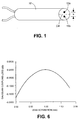
- an optical fibre tube 10 having two fibre ends 12a and 12b disposed therein and polished so that the end face of the tube and fibre ends form a planar surface.
- Sleeves or ferrules of this type are typically made of glass or a ceramic material and are manufactured to very tight tolerances of within a few ⁇ m.
- the two fibre ends 12a and 12b are disposed a same distance "b/2" from the central longitudinal axis CA of the fibre tube 10.
- Sleeves are manufactured with openings that are spaced with different distances from the central axis and wherein the offset from the central axis is the same for both openings.
- the two optical fibres shown in Fig. 2 are shown absent the fibre sleeve 10 in which they are housed.
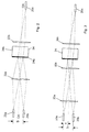
- a multilayer thin film dichroic optical filter 24 consisting of a transparent substrate 24b supporting a multi-layer thin film coating 24a is disposed between two lenses 22a and 22b in such a manner as to intercept a beam of light launched from one of the fibre ends 12a or 12b.
- the focal length and position of the lens 22a ensures that light launched from optical fibre end 20a will be substantially collimated as it impinges upon the filter 24.
- the lens 22b ensures that the beam transmitted through the filter 24 is focused at the fibre end 20c.
- the location of the lens 22a along the dotted line OA determines whether or not the beam passing therethrough will be collimated about the filter coating 24a. For a given separation between the fibre 20a and filter 24a, there is a unique position of the lens 22a along OA such that the light impinging on the filter 24a is substantially collimated.
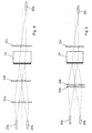
- FIGs. 3 through 5 three similar optical filter assemblies are shown, wherein a compound lens comprising two lenses 32a and 32b are disposed between the optical fibre 20a and the filter 24. As in the prior art circuit a single lens 32c is disposed between the filter and the single fibre 20c.
- Figs. 3, 4, and 5 illustrate that as the lenses 32a and 32b are brought closer together, the angle of incidence of the beam of light impinging upon the filter increases becoming steeper; alternatively, as the lenses are separated and the distance "d" between them increases, the angle of incidence upon the filter lessens.
- the filter can be tuned during manufacture to ensure a desired wavelength response of the filter. Furthermore, this affords using a standard fibre tube to contain the two optical fibres 20a and 20b or selecting one of a few standard tubes and subsequently tuning the filter by relatively moving the lenses 32a and 32b to vary the gap therebetween; in this manner a large tuning range is afforded.
- the effective focal length f eff of the compound lens combination 32a, 32b is: where f 1 is the focal length of the first lens 32a, f 2 is the focal length of the second lens 32b and d is the distance between opposing principal planes of lenses 32a and 32b, and if the lenses are "thin" d is the distance between the two lenses, 32a and 32 b,
- the effective focal length can be varied between a maximum value and a minimum value, i.e. f min ⁇ f eff ⁇ f max .
- the focal length of the single lens 32c which focuses transmitted light into the output fibre is preferably selected to be in the middle of the range for f eff .
- the graph of Fig. 6 illustrates coupling as a function of lens separation between lenses 32a and 32b over a tuning range of interest; this Gaussian coupling loss arises from a mismatch between the mode field diameter, MFD, of the output fibre and the focussed spot size at the entrance to the output fibre 20c. As shown in Fig. 6 there is an optimum focussed spot size that couples with the least loss into the fibre 20c.
- This minimum loss point occurs when the separation between lenses 32a and 32b is such that their effective focal length, f eff , is equal to the focal length of the single lens 32c. If f eff differs from the focal length of lens 32c, the spot size is too large or too small, and some loss is incurred.
- a compound lens is disposed on both sides of the filter 24. In this manner, the effective focal lengths are adjusted to be identical. Due to the additional cost and complexity of this embodiment, the more practical and cost effective embodiment is shown in Figs. 3, 4, and 5, wherein a single lens 32c is provided to focus the light into the fibre 20c.
- the device shown in Figs. 3, 4, and 5 is divided into two sides by the filter.
- One side referred to as the input side, has the input and reflection ports.
- the transmission side has the transmission port only.
- Figs. 3, 4 and 5 describe a three port device.
- an additional port may be provided on the transmission side to yield a four port device.
- Yet another embodiment is a two port device similar to Figs. 3, 4 and 5 except that the lens 32c and transmission fibre 20c are absent.
- the preferred embodiment consists of a compound lens on the input side and a singlet lens on the transmission side.
- the spacing of the elements of the compound lens 32a and 32b are adjusted while measuring the wavelength of light that is transmitted through the filter 24. Changing the spacing of the lenses changes the angle of incidence on the filter and, hence the wavelength of the transmitted light. When the desired wavelength is reached the lens spacing is fixed.
- the reflected signal is optimized.
- This requires simultaneous adjustment of the distance between the input fibre 20a and first lens 32a, referred to as the front working distance, FWD and the distance between the filter and the second element 32b of the compound lens, referred to as the back working distance, BWD by adjusting the positions of the input fibre 20a and the compound lens, whose component lenses 32a and 32b are relatively fixed, while monitoring the reflected signal.
- FWD front working distance
- BWD back working distance
- the transmission fibre tube accommodating the optical fibre 20c is positioned for optimum coupling while monitoring the transmitted test signal.
Landscapes
- Physics & Mathematics (AREA)
- General Physics & Mathematics (AREA)
- Optics & Photonics (AREA)
- Optical Couplings Of Light Guides (AREA)
- Mechanical Light Control Or Optical Switches (AREA)
- Optical Filters (AREA)
Applications Claiming Priority (2)
| Application Number | Priority Date | Filing Date | Title |
|---|---|---|---|
| US505868 | 2000-02-17 | ||
| US09/505,868 US6611642B1 (en) | 2000-02-17 | 2000-02-17 | Optical coupling arrangement |
Publications (2)
| Publication Number | Publication Date |
|---|---|
| EP1146362A2 true EP1146362A2 (fr) | 2001-10-17 |
| EP1146362A3 EP1146362A3 (fr) | 2004-05-19 |
Family
ID=24012207
Family Applications (1)
| Application Number | Title | Priority Date | Filing Date |
|---|---|---|---|
| EP01301298A Withdrawn EP1146362A3 (fr) | 2000-02-17 | 2001-02-13 | Filtre dichroique pour séparation de différentes longueurs d'onde |
Country Status (4)
| Country | Link |
|---|---|
| US (1) | US6611642B1 (fr) |
| EP (1) | EP1146362A3 (fr) |
| CN (1) | CN1309311A (fr) |
| CA (1) | CA2332763A1 (fr) |
Families Citing this family (6)
| Publication number | Priority date | Publication date | Assignee | Title |
|---|---|---|---|---|
| US6813420B1 (en) * | 2000-09-21 | 2004-11-02 | Axsun Technologies, Inc. | Process and system for tunable filter optical train alignment |
| WO2006051981A1 (fr) * | 2004-11-15 | 2006-05-18 | Hitachi Chemical Company, Ltd. | Reflecteur de lumiere, photocoupleur/filtre de derivation et systeme optique |
| ATE527565T1 (de) * | 2004-12-30 | 2011-10-15 | Proximion Fiber Systems Ab | Optischer koppler mit faser-bragg-gitter und fabry-perot-kavität entsprechende methode der nutzung |
| DE202007017386U1 (de) * | 2007-12-13 | 2008-02-28 | CCS Technology, Inc., Wilmington | Kopplungseinrichtung zum Koppeln von Lichtwellenleitern |
| WO2018146819A1 (fr) * | 2017-02-13 | 2018-08-16 | 三菱電機株式会社 | Dispositif d'oscillation laser |
| US12140416B2 (en) * | 2019-11-07 | 2024-11-12 | Spectricity | Collimating array for an optical sensing device |
Family Cites Families (8)
| Publication number | Priority date | Publication date | Assignee | Title |
|---|---|---|---|---|
| JPS61261707A (ja) * | 1985-05-16 | 1986-11-19 | Nec Corp | 光通信用光部品 |
| US5039193A (en) * | 1990-04-03 | 1991-08-13 | Focal Technologies Incorporated | Fibre optic single mode rotary joint |
| US5680237A (en) * | 1995-11-16 | 1997-10-21 | Jds Fitel Inc. | Graded index lens system and method for coupling light |
| US5917626A (en) * | 1997-02-14 | 1999-06-29 | Dicon Fiberotics, Inc. | Tunable filter for use in wavelength division multiplexer and demultiplexer |
| US6125221A (en) * | 1998-03-19 | 2000-09-26 | Lucent Technologies, Inc. | Three port optical filter |
| US6078710A (en) * | 1998-04-02 | 2000-06-20 | Oplink Communications, Inc. | Method and system for providing a multi-channel optical filter |
| JP2000028851A (ja) * | 1998-07-13 | 2000-01-28 | Mitsubishi Electric Corp | 光合分波装置 |
| US6215221B1 (en) | 1998-12-29 | 2001-04-10 | Honeywell International Inc. | Electrostatic/pneumatic actuators for active surfaces |
-
2000
- 2000-02-17 US US09/505,868 patent/US6611642B1/en not_active Expired - Fee Related
-
2001
- 2001-01-30 CA CA002332763A patent/CA2332763A1/fr not_active Abandoned
- 2001-02-13 EP EP01301298A patent/EP1146362A3/fr not_active Withdrawn
- 2001-02-16 CN CN01104616A patent/CN1309311A/zh active Pending
Also Published As
| Publication number | Publication date |
|---|---|
| US6611642B1 (en) | 2003-08-26 |
| CN1309311A (zh) | 2001-08-22 |
| CA2332763A1 (fr) | 2001-08-17 |
| EP1146362A3 (fr) | 2004-05-19 |
Similar Documents
| Publication | Publication Date | Title |
|---|---|---|
| US5612824A (en) | Narrow band filter and method of making same | |
| US6454465B1 (en) | Method of making an optical fiber collimating device | |
| US5799121A (en) | Multi-port optical device | |
| US4958897A (en) | Thin film optical component for use in optical transmission lines and method of manufacturing the same | |
| JP2786322B2 (ja) | 反射軽減集成装置 | |
| US6540411B1 (en) | Optical coupling | |
| US6860644B2 (en) | Dual fiber collimator assembly pointing control | |
| US6059462A (en) | Optical coupling system | |
| US6611642B1 (en) | Optical coupling arrangement | |
| CA2180711C (fr) | Dispositif optique comportant un film optique a variation d'angle d'incidence | |
| KR100413250B1 (ko) | 광학소자 및 그의 제조방법 | |
| US6621954B1 (en) | Precision optical filter with a ball-end joint | |
| US6876789B2 (en) | Optical filtering module and optical devices using such optical filtering module | |
| US6292604B1 (en) | Optical coupler arrangement | |
| US7171073B1 (en) | Structure and method for multi-ports optical apparatus | |
| JP3949137B2 (ja) | 光ファイバ端末とその製造方法並びに光結合器及び光部品 | |
| US6626583B2 (en) | Optical multiplexer/demultiplexer module and production method therefor | |
| KR100361441B1 (ko) | 탭 커플러 | |
| JPWO2004053547A6 (ja) | 光ファイバ端末とその製造方法並びに光結合器及び光部品 | |
| JP2004302292A (ja) | 光ファイバ端末とその作製方法並びに光結合器及び光部品 | |
| KR0170329B1 (ko) | 광통신용 광합분파기 | |
| KR0156967B1 (ko) | 광콜리메이터 및 이를 이용한 광부품 | |
| US7340130B1 (en) | Method for assembly of multi-ports optical apparatus | |
| US20020057871A1 (en) | Method for aligning optical components | |
| KR100720790B1 (ko) | 페룰 광섬유의 입사각 정밀도가 개선된 양방향 광모듈 |
Legal Events
| Date | Code | Title | Description |
|---|---|---|---|
| PUAI | Public reference made under article 153(3) epc to a published international application that has entered the european phase |
Free format text: ORIGINAL CODE: 0009012 |
|
| AK | Designated contracting states |
Kind code of ref document: A2 Designated state(s): AT BE CH CY DE DK ES FI FR GB GR IE IT LI LU MC NL PT SE TR |
|
| AX | Request for extension of the european patent |
Free format text: AL;LT;LV;MK;RO;SI |
|
| PUAL | Search report despatched |
Free format text: ORIGINAL CODE: 0009013 |
|
| AK | Designated contracting states |
Kind code of ref document: A3 Designated state(s): AT BE CH CY DE DK ES FI FR GB GR IE IT LI LU MC NL PT SE TR |
|
| AX | Request for extension of the european patent |
Extension state: AL LT LV MK RO SI |
|
| AKX | Designation fees paid | ||
| REG | Reference to a national code |
Ref country code: DE Ref legal event code: 8566 |
|
| STAA | Information on the status of an ep patent application or granted ep patent |
Free format text: STATUS: THE APPLICATION IS DEEMED TO BE WITHDRAWN |
|
| 18D | Application deemed to be withdrawn |
Effective date: 20041120 |