EP1146624A2 - Statorkern einer rotierenden elektrischen Maschine für Kraftfahrzeuge und Verfahen zur Herstellung desselben - Google Patents
Statorkern einer rotierenden elektrischen Maschine für Kraftfahrzeuge und Verfahen zur Herstellung desselben Download PDFInfo
- Publication number
- EP1146624A2 EP1146624A2 EP01108645A EP01108645A EP1146624A2 EP 1146624 A2 EP1146624 A2 EP 1146624A2 EP 01108645 A EP01108645 A EP 01108645A EP 01108645 A EP01108645 A EP 01108645A EP 1146624 A2 EP1146624 A2 EP 1146624A2
- Authority
- EP
- European Patent Office
- Prior art keywords
- teeth
- magnetic
- stator core
- circumferential
- electric machine
- Prior art date
- Legal status (The legal status is an assumption and is not a legal conclusion. Google has not performed a legal analysis and makes no representation as to the accuracy of the status listed.)
- Granted
Links
Images


Classifications
-
- H—ELECTRICITY
- H02—GENERATION; CONVERSION OR DISTRIBUTION OF ELECTRIC POWER
- H02K—DYNAMO-ELECTRIC MACHINES
- H02K15/00—Processes or apparatus specially adapted for manufacturing, assembling, maintaining or repairing of dynamo-electric machines
- H02K15/02—Processes or apparatus specially adapted for manufacturing, assembling, maintaining or repairing of dynamo-electric machines of stator or rotor bodies
- H02K15/021—Magnetic cores
-
- H—ELECTRICITY
- H02—GENERATION; CONVERSION OR DISTRIBUTION OF ELECTRIC POWER
- H02K—DYNAMO-ELECTRIC MACHINES
- H02K1/00—Details of the magnetic circuit
- H02K1/06—Details of the magnetic circuit characterised by the shape, form or construction
- H02K1/12—Stationary parts of the magnetic circuit
- H02K1/16—Stator cores with slots for windings
-
- H—ELECTRICITY
- H02—GENERATION; CONVERSION OR DISTRIBUTION OF ELECTRIC POWER
- H02K—DYNAMO-ELECTRIC MACHINES
- H02K15/00—Processes or apparatus specially adapted for manufacturing, assembling, maintaining or repairing of dynamo-electric machines
- H02K15/02—Processes or apparatus specially adapted for manufacturing, assembling, maintaining or repairing of dynamo-electric machines of stator or rotor bodies
- H02K15/021—Magnetic cores
- H02K15/026—Wound cores
-
- H—ELECTRICITY
- H02—GENERATION; CONVERSION OR DISTRIBUTION OF ELECTRIC POWER
- H02K—DYNAMO-ELECTRIC MACHINES
- H02K1/00—Details of the magnetic circuit
- H02K1/06—Details of the magnetic circuit characterised by the shape, form or construction
- H02K1/12—Stationary parts of the magnetic circuit
- H02K1/16—Stator cores with slots for windings
- H02K1/165—Shape, form or location of the slots
-
- Y—GENERAL TAGGING OF NEW TECHNOLOGICAL DEVELOPMENTS; GENERAL TAGGING OF CROSS-SECTIONAL TECHNOLOGIES SPANNING OVER SEVERAL SECTIONS OF THE IPC; TECHNICAL SUBJECTS COVERED BY FORMER USPC CROSS-REFERENCE ART COLLECTIONS [XRACs] AND DIGESTS
- Y10—TECHNICAL SUBJECTS COVERED BY FORMER USPC
- Y10T—TECHNICAL SUBJECTS COVERED BY FORMER US CLASSIFICATION
- Y10T29/00—Metal working
- Y10T29/49—Method of mechanical manufacture
- Y10T29/49002—Electrical device making
- Y10T29/49009—Dynamoelectric machine
- Y10T29/49012—Rotor
-
- Y—GENERAL TAGGING OF NEW TECHNOLOGICAL DEVELOPMENTS; GENERAL TAGGING OF CROSS-SECTIONAL TECHNOLOGIES SPANNING OVER SEVERAL SECTIONS OF THE IPC; TECHNICAL SUBJECTS COVERED BY FORMER USPC CROSS-REFERENCE ART COLLECTIONS [XRACs] AND DIGESTS
- Y10—TECHNICAL SUBJECTS COVERED BY FORMER USPC
- Y10T—TECHNICAL SUBJECTS COVERED BY FORMER US CLASSIFICATION
- Y10T29/00—Metal working
- Y10T29/49—Method of mechanical manufacture
- Y10T29/49002—Electrical device making
- Y10T29/4902—Electromagnet, transformer or inductor
- Y10T29/49071—Electromagnet, transformer or inductor by winding or coiling
-
- Y—GENERAL TAGGING OF NEW TECHNOLOGICAL DEVELOPMENTS; GENERAL TAGGING OF CROSS-SECTIONAL TECHNOLOGIES SPANNING OVER SEVERAL SECTIONS OF THE IPC; TECHNICAL SUBJECTS COVERED BY FORMER USPC CROSS-REFERENCE ART COLLECTIONS [XRACs] AND DIGESTS
- Y10—TECHNICAL SUBJECTS COVERED BY FORMER USPC
- Y10T—TECHNICAL SUBJECTS COVERED BY FORMER US CLASSIFICATION
- Y10T29/00—Metal working
- Y10T29/49—Method of mechanical manufacture
- Y10T29/49002—Electrical device making
- Y10T29/4902—Electromagnet, transformer or inductor
- Y10T29/49073—Electromagnet, transformer or inductor by assembling coil and core
Definitions
- the present invention relates to a stator core of a vehicle rotary electric machine, such as an AC generator, to be mounted in a passenger car, a truck, etc.
- a magnetic stator core is usually comprised of a spirally wound magnetic strip.
- Such a stator core can provide a high yield percentage of magnetic material and can be manufactured at a high manufacturing speed.
- conductors are to be disposed in the slots of the stator core at as a high space factor as possible.
- a pair long and thin magnetic sheets is stamped out to form a pair of magnetic strips that has a plurality of teeth and a core back in order to increase the yield percentage of the magnetic strips, the teeth of one of the pair of magnetic strips are respectively formed from portions inside slots of the other magnetic strip.
- each the magnetic strip is spirally wound into a cylindrical stack with the slots of one layer being aligned with those of another layer until the cylindrical stack has a prescribed thickness. Then, the stack is welded or riveted. Because two or more magnetic strips are formed at one time, the manpower and cost for manufacturing the stator cores can be reduced.
- JP-A-48-24204 discloses teeth whose tooth width becomes narrower toward the core back. In other words, slot width is widened at the middle thereof. This reduces strain of the strip when it is spirally wound and makes the size and shape of a cylindrical stator core accurate.
- each tooth has a pair of circumferential projections to increase the width of the tooth.
- the slot area is narrowed to thereby widen the cross-section of the tooth. If the teeth of one of the pair of magnetic strips are respectively formed from portions inside slots of the other magnetic strip as disclosed in JP-A-299136, it is not possible to provide such a circumferentially wide tooth.
- tooth width is narrowed at the middle thereof as shown in JP-A-48-24204, a widened tooth edge of one of a pair of magnetic strips can be formed from the portion inside a widened slot of the other magnetic strip.
- the tooth is narrowed at the middle, the magnetic reluctance of the teeth increases, and the magnetic flux flowing through the stator core decreases significantly. This lowers the output. power.
- a stator core of a vehicle AC generator that has an outside diameter between 90 mm and 140 mm is usually comprised of a laminated steel strip of a thickness between 0.5 mm and 1.0 mm. It is necessary to have a margin (or clearance) if teeth and slots are formed from a steel strip of the above thickness.
- the edge of the sheet may be drawn because of the low rigidity thereof.
- the projections of the tooth edge can not have proper length, and a sufficient cross-section of the magnetic flux from the rotor can not be provided.
- a main object of the invention is to provide a powerful and inexpensive vehicle rotary electric machine having a stator core that is free from the above problems.
- the invention is to provide a stator core of a powerful vehicle rotary machine that can be manufactured at a high yield percentage and a high speed.
- the invention is to improve the yield percentage of the magnetic strip forming the stator core, to reduce manpower of manufacturing the magnetic strip, to reduce the magnetic reluctance of the stator core and to improve the space factor of the conductor coils.
- each of teeth of the stator core has at least a circumferential projection at an inner edge thereof and at least a circumferentially extending notch at a base portion thereof, and a circumferential width of the teeth at the base portion is wider than a circumferential width of the teeth at the tooth edge from which the projection extends.
- the cross-section of the teeth at the middle thereof is not narrower than the cross-section at the base thereof. This shape prevents the magnetic reluctance thereof from increasing. In addition, it is possible to manufacture a plurality of magnetic strips from a long magnetic sheet.
- the yield percentage of the magnetic strip can be improved and the manpower for manufacturing the magnetic strip can be reduced.
- the magnetic strip can be wound easily because of the notches.
- the notch and projection are complementary to each other in shape before the magnetic strip is spirally wound, and the width of the notch is reduced after the strip is wound. Therefore, the yield percentage of the magnetic strip is drastically improved. Because the radial width of the notch is automatically reduced when the magnetic strip is wound, the magnetic reluctance from the teeth to the core back can be reduced.
- the slot has parallel walls facing each other in circumferential directions. Therefore, it is easy to align the conductors in the slots, resulting in improvement of the space factor.
- the magnetic strip is thicker than 0.2 mm and thinner than 0.5 mm. This thickness makes it possible to form the magnetic strips with small marginal portions and stamp out two magnetic strips at once in order to reduce cost and prevents the tooth edge from deforming.
- the invention can be applied to a vehicle rotary electric machine such as a generator or a motor.
- a vehicle rotary electric machine such as a generator or a motor.
- it is mounted in an engine and driven by the engine as an AC generator. It is also mounted in an engine as a motor.
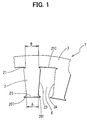
- a stator core of a vehicle AC generator according to a first embodiment of the invention is described with reference to Figs. 1 - 5.
- a cylindrical stator core 1 is comprised of a spirally wound and laminated magnetic strip 10 that is as thick as 0.35 mm.
- the magnetic strip 10 has a plurality of teeth 2 and a core back 3 from which the plurality of teeth 2 extends. When wound and laminated, tooth edges 20 of teeth 2 are disposed radially inside, as shown in Fig. 3.
- a plurality of conductor coils 5 is disposed in each slot 6 formed between adjacent teeth 2, as shown in Fig. 5, so that an electromotive force can be generated in the conductor coils 5 when a rotor having a field coil (not shown) supplies an alternating magnetic flux.
- a pair of circumferential notches 21 is formed at opposite sides of a base portion of each tooth 2 adjacent to the core back 3.
- a width B of the base between the notches 21 is set larger than a minimum width A between a pair of circumferential projections 201 formed at the tooth edge 20.
- Each slot 6 has a pair of walls 23 and 24 facing each other in the circumferential direction. The pair of walls 23 and 24 becomes parallel after the magnetic strip 10 is wound up.
- the pair of projections 201 is almost the same in shape as a slot bottom 210 that includes the pair of notches 21.
- a pair of magnetic strips 10 is formed from a long and thin magnetic sheet 100 such as a hoop of a steel sheet, the tooth edges 20 of one magnetic strip 10 and the slot bottom 210 of the other magnetic strip 10 is sheared and separated without any clearance or margin except for clearances or marginal portions 200 at opposite sides of each tooth 2, as shown in Fig. 2. This increases the yield percentage of the magnetic strip. Because the thickness of the magnetic strip 10 is 0.35 mm, the projections 201 do not deform and keep the magnetic reluctance at a low level.
- the magnetic cross-section of the teeth 2 is the smallest at the base of the projections 201, i.e. at the tooth edge 20 from which the projections 201 extend.
- the cross-section of middle portion of the teeth 2 between the base of the projections 201 and the core back 3 is not smaller than the magnetic cross-section at the base of the projections 201.
- the radial width of each notch 21 is narrowed when the magnetic strip 10 is spirally wound. Accordingly, the magnetic reluctance around the notches 21 is reduced when the stator core 1 is completed.
- a plurality of magnetic strips 10 can be formed from a single long and thin magnetic sheet 100, and the notches 21 make the winding step of the magnetic strip 10 easier.
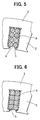
- the parallel walls 23 and 24 make it easy to align the conductor coils in the slot 6, as shown in Fig. 5 so that a high space factor can be provided, resulting in a high power generator.
- the conductor coils can have a rectangular cross-section to be fitted to the inside walls of each slot 6 including parallel walls, as shown in Fig. 6. This increases the space factor so that more output power can be provided.
- a pair of magnetic strips that is overlapped each other can be stamped as shown in Fig. 7. This step reduces time of manufacturing magnetic strips 10. It is also possible to stamp out three overlapping magnetic strips at one time. Because the thickness of the magnetic strip 10 is comparatively small, the iron loss of the stator core can be reduced to increase the output power.
- a long magnetic sheet can be loaded between a pair of parallel rollers having a punch and a die to stamp out the magnetic strip 10 continuously, as shown in Fig. 8. Because the magnetic strip 10 can be formed continuously, the production time and cost can be reduced.
- the thickness of the magnetic sheets can be changed from 0.35 mm to a thickness between 0.2 mm and 0.5 mm.
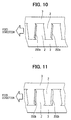
- a stator core according to a fourth embodiment of the invention is described with reference to Fig. 9.
- a unit of the conductor coils 5 can be divided into two groups, and each output power is added to each other.
- the number of the slots per each unit length of the magnetic sheet becomes twice as many as the number of the slots of the magnetic sheet according to the first embodiment.
- the width of the slots becomes a half the width of the slot of the magnetic sheet according to the first embodiment.
- the clearance 200a for stamping out can be formed at a side of each tooth 2, as shown in Fig. 10. Because the width of the clearance can be increased, the magnetic strips can be stamped out more easily.
- the pair of magnetic strips can be formed by the pair of parallel rollers, as shown in Fig. 8.
- a clearance 200b can be increased until the notches at the base of the teeth 2 are removed. This makes the manufacturing steps easier and the manufacturing cost lower.
Landscapes
- Engineering & Computer Science (AREA)
- Power Engineering (AREA)
- Manufacturing & Machinery (AREA)
- Iron Core Of Rotating Electric Machines (AREA)
- Manufacture Of Motors, Generators (AREA)
- Windings For Motors And Generators (AREA)
- Insulation, Fastening Of Motor, Generator Windings (AREA)
Priority Applications (1)
| Application Number | Priority Date | Filing Date | Title |
|---|---|---|---|
| EP02019090A EP1276210B1 (de) | 2000-04-14 | 2001-04-05 | Verfahren und Vorrichtung zur Herstellung eines Statorkerns einer rotierenden elektrischen Maschine für Kraftfahrzeuge |
Applications Claiming Priority (4)
| Application Number | Priority Date | Filing Date | Title |
|---|---|---|---|
| JP2000113966 | 2000-04-14 | ||
| JP2000113966 | 2000-04-14 | ||
| JP2000359639 | 2000-11-27 | ||
| JP2000359639A JP3656733B2 (ja) | 2000-04-14 | 2000-11-27 | 車両用回転電機の固定子、およびその製造方法 |
Related Child Applications (1)
| Application Number | Title | Priority Date | Filing Date |
|---|---|---|---|
| EP02019090A Division EP1276210B1 (de) | 2000-04-14 | 2001-04-05 | Verfahren und Vorrichtung zur Herstellung eines Statorkerns einer rotierenden elektrischen Maschine für Kraftfahrzeuge |
Publications (3)
| Publication Number | Publication Date |
|---|---|
| EP1146624A2 true EP1146624A2 (de) | 2001-10-17 |
| EP1146624A3 EP1146624A3 (de) | 2001-11-21 |
| EP1146624B1 EP1146624B1 (de) | 2003-11-05 |
Family
ID=26590162
Family Applications (2)
| Application Number | Title | Priority Date | Filing Date |
|---|---|---|---|
| EP01108645A Expired - Lifetime EP1146624B1 (de) | 2000-04-14 | 2001-04-05 | Statorkern einer rotierenden elektrischen Maschine für Kraftfahrzeuge und Verfarhen zur Herstellung desselben |
| EP02019090A Expired - Lifetime EP1276210B1 (de) | 2000-04-14 | 2001-04-05 | Verfahren und Vorrichtung zur Herstellung eines Statorkerns einer rotierenden elektrischen Maschine für Kraftfahrzeuge |
Family Applications After (1)
| Application Number | Title | Priority Date | Filing Date |
|---|---|---|---|
| EP02019090A Expired - Lifetime EP1276210B1 (de) | 2000-04-14 | 2001-04-05 | Verfahren und Vorrichtung zur Herstellung eines Statorkerns einer rotierenden elektrischen Maschine für Kraftfahrzeuge |
Country Status (4)
| Country | Link |
|---|---|
| US (2) | US6559572B2 (de) |
| EP (2) | EP1146624B1 (de) |
| JP (1) | JP3656733B2 (de) |
| DE (2) | DE60120953T2 (de) |
Cited By (6)
| Publication number | Priority date | Publication date | Assignee | Title |
|---|---|---|---|---|
| WO2005107037A1 (de) * | 2004-04-30 | 2005-11-10 | Thyssenkrupp Transrapid Gmbh | Statorpaket für magnetschwebebahnen |
| DE102006016249A1 (de) * | 2006-03-31 | 2007-10-04 | Robert Bosch Gmbh | Stator für eine Elektromaschine und Verfahren zur Herstellung |
| CN102959833A (zh) * | 2010-06-25 | 2013-03-06 | 三菱电机株式会社 | 旋转电机的层叠铁芯 |
| CN103430435A (zh) * | 2011-04-29 | 2013-12-04 | 三菱电机株式会社 | 线性马达的层叠铁心及其制造方法 |
| EP3367539A1 (de) * | 2017-02-28 | 2018-08-29 | Hamilton Sundstrand Corporation | Elektrische maschinenbleche |
| EP3879673A1 (de) * | 2020-03-11 | 2021-09-15 | Siemens Gamesa Renewable Energy A/S | Laminierter segmentkern für einen stator oder rotor eines generators fuer eine windkraftanlage |
Families Citing this family (74)
| Publication number | Priority date | Publication date | Assignee | Title |
|---|---|---|---|---|
| JP4327960B2 (ja) * | 1999-10-25 | 2009-09-09 | 富士通株式会社 | 電子メール端末装置及びコンピュータ可読媒体 |
| SE516002C2 (sv) * | 2000-03-01 | 2001-11-05 | Abb Ab | Roterande elektrisk maskin samt förfarande för framställning av en statorlindning |
| JP3960122B2 (ja) * | 2002-05-01 | 2007-08-15 | 株式会社デンソー | 電動圧縮機 |
| DE10245691A1 (de) * | 2002-09-30 | 2004-04-08 | Robert Bosch Gmbh | Ständer für eine elektrische Maschine |
| JP4042612B2 (ja) | 2003-04-11 | 2008-02-06 | 株式会社デンソー | 回転電機の回転子およびその製造方法 |
| US7271519B2 (en) * | 2003-10-02 | 2007-09-18 | Lg Electronics Inc. | Laminated body of motor and manufacturing method thereof |
| US7728481B2 (en) * | 2003-10-02 | 2010-06-01 | Lg Electronics Inc. | Laminated body of motor and manufacturing method thereof |
| KR100565652B1 (ko) * | 2003-12-30 | 2006-03-30 | 엘지전자 주식회사 | 톱로딩 방식 드럼세탁기의 구동부 |
| KR101033579B1 (ko) * | 2004-03-03 | 2011-05-11 | 엘지전자 주식회사 | 드럼세탁기용 아웃터로터형 모터의 스테이터 구조 |
| KR101033573B1 (ko) * | 2004-02-26 | 2011-05-11 | 엘지전자 주식회사 | 드럼세탁기용 아웃터로터형 모터의 스테이터 구조 |
| US7362028B2 (en) * | 2004-02-26 | 2008-04-22 | Lg Electronics Inc. | Stator of outer rotor type motor for drum type washer |
| KR101033580B1 (ko) * | 2004-03-03 | 2011-05-11 | 엘지전자 주식회사 | 스파이럴 코어의 구조 및 이의 제조방법 |
| JP4798965B2 (ja) * | 2004-05-31 | 2011-10-19 | 株式会社東芝 | 回転機鉄心の製造方法 |
| DE102004034526A1 (de) * | 2004-07-16 | 2006-02-16 | Elmotec Statomat Vertriebs Gmbh | Stator für elektrische Maschinen |
| US6989622B1 (en) | 2004-11-23 | 2006-01-24 | Visteon Global Technologies, Inc. | Alternator having claw-pole rotor |
| JP2006345671A (ja) * | 2005-06-10 | 2006-12-21 | Denso Corp | 車両用回転電機 |
| US7536526B2 (en) * | 2005-07-11 | 2009-05-19 | General Electric Company | Hierarchical state based migration of structured data |
| DE102006034109A1 (de) * | 2006-07-24 | 2008-01-31 | Robert Bosch Gmbh | Radiale Zentrierfläche eines Ständekerns |
| JP5061788B2 (ja) * | 2007-08-10 | 2012-10-31 | トヨタ自動車株式会社 | ステータ |
| US7939984B2 (en) * | 2007-10-30 | 2011-05-10 | Woodward Hrt, Inc. | Lamination having tapered tooth geometry which is suitable for use in electric motor |
| JPWO2010103634A1 (ja) * | 2009-03-11 | 2012-09-10 | 株式会社日立製作所 | 車両用交流発電機 |
| WO2011042036A1 (en) * | 2009-10-09 | 2011-04-14 | Thyssenkrupp Aufzugswerke Gmbh | Elevator drive |
| EP2309624A1 (de) | 2009-10-09 | 2011-04-13 | ThyssenKrupp Aufzugswerke GmbH | Aufzugantrieb |
| EP2567450A4 (de) | 2010-05-04 | 2018-01-17 | Remy Technologies, LLC | Kühlsystem und -verfahren für eine elektromaschine |
| US8659191B2 (en) | 2010-05-18 | 2014-02-25 | Remy Technologies, Llc | Sleeve member for an electric machine |
| DE112011101912T5 (de) | 2010-06-04 | 2013-03-28 | Remy Technologies Llc. | Kühlsystem und -verfahren für eine elektrische Maschine |
| US8519581B2 (en) | 2010-06-08 | 2013-08-27 | Remy Technologies, Llc | Electric machine cooling system and method |
| JP2013528353A (ja) | 2010-06-08 | 2013-07-08 | レミー テクノロジーズ リミテッド ライアビリティー カンパニー | 電気機械冷却システム及び方法 |
| US8456046B2 (en) * | 2010-06-08 | 2013-06-04 | Remy Technologies, Llc | Gravity fed oil cooling for an electric machine |
| US8269383B2 (en) * | 2010-06-08 | 2012-09-18 | Remy Technologies, Llc | Electric machine cooling system and method |
| US8482169B2 (en) | 2010-06-14 | 2013-07-09 | Remy Technologies, Llc | Electric machine cooling system and method |
| US8552600B2 (en) | 2010-06-14 | 2013-10-08 | Remy Technologies, Llc | Potted end turns of an electric machine |
| US8614538B2 (en) | 2010-06-14 | 2013-12-24 | Remy Technologies, Llc | Electric machine cooling system and method |
| US8446056B2 (en) | 2010-09-29 | 2013-05-21 | Remy Technologies, Llc | Electric machine cooling system and method |
| US8508085B2 (en) | 2010-10-04 | 2013-08-13 | Remy Technologies, Llc | Internal cooling of stator assembly in an electric machine |
| US8492952B2 (en) | 2010-10-04 | 2013-07-23 | Remy Technologies, Llc | Coolant channels for electric machine stator |
| US8395287B2 (en) | 2010-10-04 | 2013-03-12 | Remy Technologies, Llc | Coolant channels for electric machine stator |
| US8593021B2 (en) | 2010-10-04 | 2013-11-26 | Remy Technologies, Llc | Coolant drainage system and method for electric machines |
| US8546983B2 (en) | 2010-10-14 | 2013-10-01 | Remy Technologies, Llc | Split drain system and method for an electric machine module |
| US8648506B2 (en) | 2010-11-09 | 2014-02-11 | Remy Technologies, Llc | Rotor lamination cooling system and method |
| US8497608B2 (en) | 2011-01-28 | 2013-07-30 | Remy Technologies, Llc | Electric machine cooling system and method |
| CN103415979B (zh) * | 2011-03-08 | 2016-10-26 | 松下电器产业株式会社 | 电动机的定子以及电动机 |
| WO2012145302A2 (en) | 2011-04-18 | 2012-10-26 | Remy Technologies, Llc | Electric machine module cooling system and method |
| US8692425B2 (en) | 2011-05-10 | 2014-04-08 | Remy Technologies, Llc | Cooling combinations for electric machines |
| US8803380B2 (en) | 2011-06-03 | 2014-08-12 | Remy Technologies, Llc | Electric machine module cooling system and method |
| JP5638475B2 (ja) * | 2011-07-01 | 2014-12-10 | 三菱電機株式会社 | リニアモータの積層鉄心およびその製造方法 |
| US9041260B2 (en) | 2011-07-08 | 2015-05-26 | Remy Technologies, Llc | Cooling system and method for an electronic machine |
| US8803381B2 (en) | 2011-07-11 | 2014-08-12 | Remy Technologies, Llc | Electric machine with cooling pipe coiled around stator assembly |
| US8546982B2 (en) | 2011-07-12 | 2013-10-01 | Remy Technologies, Llc | Electric machine module cooling system and method |
| US9048710B2 (en) | 2011-08-29 | 2015-06-02 | Remy Technologies, Llc | Electric machine module cooling system and method |
| US8975792B2 (en) | 2011-09-13 | 2015-03-10 | Remy Technologies, Llc | Electric machine module cooling system and method |
| US8901789B2 (en) | 2011-10-07 | 2014-12-02 | Remy Technologies, Llc | Electric machine module |
| US9634529B2 (en) * | 2011-12-05 | 2017-04-25 | Fisher & Paykel Appliances Ltd. | Electrical machine |
| US9099900B2 (en) | 2011-12-06 | 2015-08-04 | Remy Technologies, Llc | Electric machine module cooling system and method |
| KR101306317B1 (ko) * | 2012-01-11 | 2013-09-09 | 백서재 | 타발공법에 있어서 발전기 코어의 쇼트 방지를 위한 금형 및 그의 제품 |
| US8941274B2 (en) | 2012-03-23 | 2015-01-27 | Whirlpool Corporation | Stator for an electric motor of a washing machine and method of manufacturing the same |
| US9331543B2 (en) | 2012-04-05 | 2016-05-03 | Remy Technologies, Llc | Electric machine module cooling system and method |
| US10069375B2 (en) | 2012-05-02 | 2018-09-04 | Borgwarner Inc. | Electric machine module cooling system and method |
| WO2013188742A2 (en) * | 2012-06-15 | 2013-12-19 | Vasostar, Inc. | Magnet orientation and positioning sysetm, method and apparatus |
| TWI459688B (zh) | 2012-10-19 | 2014-11-01 | Ind Tech Res Inst | 捲繞式定子芯結構 |
| GB2502385B (en) * | 2012-11-15 | 2014-07-09 | Emiliane Trancerie Spa | Method and apparatus for producing cores for electrical machines |
| JP6079240B2 (ja) * | 2013-01-08 | 2017-02-15 | トヨタ自動車株式会社 | 回転電機用ステータおよび回転電機 |
| CN104051387B (zh) * | 2013-03-15 | 2017-01-18 | 台湾积体电路制造股份有限公司 | 使用预制金属柱的金属柱接合 |
| US9263407B2 (en) | 2013-03-15 | 2016-02-16 | Taiwan Semiconductor Manufacturing Company, Ltd. | Method for manufacturing a plurality of metal posts |
| JP6214951B2 (ja) | 2013-07-19 | 2017-10-18 | 株式会社三井ハイテック | 帯状固定子鉄心片の製造方法及びこれに用いる金型装置 |
| US9614406B2 (en) | 2013-09-16 | 2017-04-04 | Nidec Motor Corporation | Wedge for stator having overmolded insulation |
| US9479022B2 (en) | 2013-09-16 | 2016-10-25 | Nidec Motor Corporation | Stator tooth wire retention wings |
| JP6248566B2 (ja) * | 2013-11-18 | 2017-12-20 | 株式会社デンソー | 回転電機の固定子鉄心およびその製造方法 |
| CN107925279B (zh) * | 2015-09-18 | 2019-12-24 | 爱信艾达株式会社 | 旋转电机和定子 |
| KR102478369B1 (ko) * | 2020-10-13 | 2022-12-16 | 엘지전자 주식회사 | 팬 모터 |
| CN112803630B (zh) * | 2021-03-22 | 2021-12-31 | 湖南科技大学 | 交流牵引电机降噪优化设计方法 |
| US11817741B2 (en) * | 2021-03-23 | 2023-11-14 | Ford Global Technologies, Llc | Electrified vehicle having electric machine stator with slot pocket |
| JPWO2024004437A1 (de) * | 2022-06-30 | 2024-01-04 | ||
| DE102024102667A1 (de) * | 2024-01-31 | 2025-07-31 | Schaeffler Technologies AG & Co. KG | Stator einer elektrischen Rotationsmaschine sowie ein Verfahren zur Herstellung eines Stators |
Family Cites Families (16)
| Publication number | Priority date | Publication date | Assignee | Title |
|---|---|---|---|---|
| US2845555A (en) * | 1955-09-12 | 1958-07-29 | Westinghouse Electric Corp | Motors |
| US3029403A (en) * | 1958-05-23 | 1962-04-10 | Honeywell Regulator Co | Magnetic core structures |
| US3283399A (en) * | 1964-03-11 | 1966-11-08 | Gen Electric | Method of forming electromagnetic cores |
| JPS5341321B1 (de) * | 1971-07-30 | 1978-11-02 | ||
| US3886256A (en) * | 1971-07-30 | 1975-05-27 | Hitachi Ltd | Stator core for rotary electric machines and method of manufacturing the same |
| JPS5494603A (en) * | 1978-01-10 | 1979-07-26 | Mitsubishi Electric Corp | Rotor core of revolving armature and its manufacture |
| US4260925A (en) * | 1978-04-17 | 1981-04-07 | Barrett Edward L | Stator for an electromagnetic transducer |
| JPS5725139A (en) * | 1980-07-21 | 1982-02-09 | Mitsui Haitetsuku:Kk | Manufacture of laminated core |
| JPS5785552A (en) * | 1980-11-13 | 1982-05-28 | Nippon Denso Co Ltd | Manufacture of core material of core for rotary electric machine |
| DE3110339C2 (de) * | 1981-03-17 | 1984-09-27 | Thyssen Industrie Ag, 4300 Essen | Verfahren zum Herstellen eines Blechpakets für einen Langstator-Linearmotor |
| US4613780A (en) * | 1984-10-12 | 1986-09-23 | General Electric Company | Lanced strip and edgewise wound core |
| US4914934A (en) * | 1984-10-12 | 1990-04-10 | General Electric Company | Method of forming an edgewise wound core |
| EP0823771B1 (de) * | 1996-02-23 | 2006-04-26 | Matsushita Electric Industrial Co., Ltd. | Motor |
| JP3359863B2 (ja) * | 1998-04-08 | 2002-12-24 | 三菱電機株式会社 | 固定子鉄芯の製造方法 |
| EP0961384B1 (de) * | 1998-05-25 | 2005-02-09 | Denso Corporation | Kraftfahrzeugwechselstromgenerator und Herstellungsverfahren |
| JP3538039B2 (ja) * | 1998-10-23 | 2004-06-14 | 三菱電機株式会社 | 交流発電機 |
-
2000
- 2000-11-27 JP JP2000359639A patent/JP3656733B2/ja not_active Expired - Lifetime
-
2001
- 2001-04-05 DE DE60120953T patent/DE60120953T2/de not_active Expired - Lifetime
- 2001-04-05 DE DE60101111T patent/DE60101111T2/de not_active Expired - Lifetime
- 2001-04-05 EP EP01108645A patent/EP1146624B1/de not_active Expired - Lifetime
- 2001-04-05 EP EP02019090A patent/EP1276210B1/de not_active Expired - Lifetime
- 2001-04-06 US US09/827,213 patent/US6559572B2/en not_active Expired - Fee Related
-
2003
- 2003-02-24 US US10/370,709 patent/US7010846B2/en not_active Expired - Fee Related
Cited By (10)
| Publication number | Priority date | Publication date | Assignee | Title |
|---|---|---|---|---|
| WO2005107037A1 (de) * | 2004-04-30 | 2005-11-10 | Thyssenkrupp Transrapid Gmbh | Statorpaket für magnetschwebebahnen |
| DE102006016249A1 (de) * | 2006-03-31 | 2007-10-04 | Robert Bosch Gmbh | Stator für eine Elektromaschine und Verfahren zur Herstellung |
| US8344580B2 (en) | 2006-03-31 | 2013-01-01 | Robert Bosch Gmbh | Stator for a polyphase electric machine and method for manufacturing same |
| CN102959833A (zh) * | 2010-06-25 | 2013-03-06 | 三菱电机株式会社 | 旋转电机的层叠铁芯 |
| CN102959833B (zh) * | 2010-06-25 | 2015-01-28 | 三菱电机株式会社 | 旋转电机的层叠铁芯 |
| EP2587632A4 (de) * | 2010-06-25 | 2018-01-17 | Mitsubishi Electric Corporation | Laminatkern für eine dynamoelektrische maschine |
| CN103430435A (zh) * | 2011-04-29 | 2013-12-04 | 三菱电机株式会社 | 线性马达的层叠铁心及其制造方法 |
| CN103430435B (zh) * | 2011-04-29 | 2016-03-02 | 三菱电机株式会社 | 线性马达的层叠铁心及其制造方法 |
| EP3367539A1 (de) * | 2017-02-28 | 2018-08-29 | Hamilton Sundstrand Corporation | Elektrische maschinenbleche |
| EP3879673A1 (de) * | 2020-03-11 | 2021-09-15 | Siemens Gamesa Renewable Energy A/S | Laminierter segmentkern für einen stator oder rotor eines generators fuer eine windkraftanlage |
Also Published As
| Publication number | Publication date |
|---|---|
| US7010846B2 (en) | 2006-03-14 |
| DE60120953D1 (de) | 2006-08-03 |
| JP2001359246A (ja) | 2001-12-26 |
| DE60101111D1 (de) | 2003-12-11 |
| EP1146624A3 (de) | 2001-11-21 |
| EP1146624B1 (de) | 2003-11-05 |
| DE60101111T2 (de) | 2004-08-19 |
| JP3656733B2 (ja) | 2005-06-08 |
| US6559572B2 (en) | 2003-05-06 |
| US20030127942A1 (en) | 2003-07-10 |
| DE60120953T2 (de) | 2006-12-21 |
| US20010030484A1 (en) | 2001-10-18 |
| EP1276210A1 (de) | 2003-01-15 |
| EP1276210B1 (de) | 2006-06-21 |
Similar Documents
| Publication | Publication Date | Title |
|---|---|---|
| US6559572B2 (en) | Stator core of vehicle rotary electric machine and method of manufacturing the same | |
| US6317962B1 (en) | Method for producing a stator of an alternating-current dynamo-electric machine | |
| EP1766757B1 (de) | Statorkern einer dynamoelektrischen maschine mit mini-kappen | |
| JP4998450B2 (ja) | ステータの製造方法 | |
| US8354770B2 (en) | Alternator for motor vehicles | |
| CN105932807A (zh) | 分段导线、定子、旋转电机、车辆以及分段导线的制造方法 | |
| CN103378701A (zh) | 用于马达的转子和马达 | |
| US20030033709A1 (en) | High slot-fill stator | |
| US20010005104A1 (en) | Stator for dynamo-electric machine | |
| CN107251370A (zh) | 旋转电机及其制造方法 | |
| US20070267932A1 (en) | Stator for inner rotor type rotating electric machine | |
| JPH10304608A (ja) | 電動機 | |
| US7239059B2 (en) | Stator of rotating electric machine and manufacturing method of the stator | |
| CN110635584A (zh) | 定子及旋转电机 | |
| JPS5915459B2 (ja) | 電気機械の磁気回路 | |
| JP2932883B2 (ja) | 電動機用ステータ鉄心および電動機用ステータ鉄心の製造方法 | |
| US7009322B2 (en) | Rotor of rotary electric machine and method of manufacturing the rotor | |
| WO2021064883A1 (ja) | 回転電機 | |
| JP2006230081A (ja) | 電動機のステータ | |
| JP2000245081A (ja) | 直流電動機用ステータ及びその製造方法 | |
| EP4340192A1 (de) | Statorkern mit axialem fluss | |
| JP2000295801A (ja) | 分割形ステータコア | |
| US20220140668A1 (en) | Electric Machine and Method for Manufacture | |
| JP3307542B2 (ja) | 車両用交流発電機の固定子鉄心 | |
| JP2003348777A (ja) | 回転電機の固定子 |
Legal Events
| Date | Code | Title | Description |
|---|---|---|---|
| PUAI | Public reference made under article 153(3) epc to a published international application that has entered the european phase |
Free format text: ORIGINAL CODE: 0009012 |
|
| PUAL | Search report despatched |
Free format text: ORIGINAL CODE: 0009013 |
|
| AK | Designated contracting states |
Kind code of ref document: A2 Designated state(s): DE FR GB IT Kind code of ref document: A2 Designated state(s): AT BE CH CY DE DK ES FI FR GB GR IE IT LI LU MC NL PT SE TR |
|
| AX | Request for extension of the european patent |
Free format text: AL;LT;LV;MK;RO;SI |
|
| 17P | Request for examination filed |
Effective date: 20010914 |
|
| AK | Designated contracting states |
Kind code of ref document: A3 Designated state(s): AT BE CH CY DE DK ES FI FR GB GR IE IT LI LU MC NL PT SE TR |
|
| AX | Request for extension of the european patent |
Free format text: AL;LT;LV;MK;RO;SI |
|
| AKX | Designation fees paid |
Free format text: DE FR GB IT |
|
| 17Q | First examination report despatched |
Effective date: 20020708 |
|
| GRAH | Despatch of communication of intention to grant a patent |
Free format text: ORIGINAL CODE: EPIDOS IGRA |
|
| GRAS | Grant fee paid |
Free format text: ORIGINAL CODE: EPIDOSNIGR3 |
|
| GRAA | (expected) grant |
Free format text: ORIGINAL CODE: 0009210 |
|
| AK | Designated contracting states |
Kind code of ref document: B1 Designated state(s): DE FR GB IT |
|
| REG | Reference to a national code |
Ref country code: GB Ref legal event code: FG4D |
|
| REF | Corresponds to: |
Ref document number: 60101111 Country of ref document: DE Date of ref document: 20031211 Kind code of ref document: P |
|
| ET | Fr: translation filed | ||
| PLBE | No opposition filed within time limit |
Free format text: ORIGINAL CODE: 0009261 |
|
| STAA | Information on the status of an ep patent application or granted ep patent |
Free format text: STATUS: NO OPPOSITION FILED WITHIN TIME LIMIT |
|
| 26N | No opposition filed |
Effective date: 20040806 |
|
| REG | Reference to a national code |
Ref country code: FR Ref legal event code: PLFP Year of fee payment: 16 |
|
| REG | Reference to a national code |
Ref country code: FR Ref legal event code: PLFP Year of fee payment: 17 |
|
| REG | Reference to a national code |
Ref country code: FR Ref legal event code: PLFP Year of fee payment: 18 |
|
| PGFP | Annual fee paid to national office [announced via postgrant information from national office to epo] |
Ref country code: DE Payment date: 20200420 Year of fee payment: 20 Ref country code: FR Payment date: 20200420 Year of fee payment: 20 |
|
| PGFP | Annual fee paid to national office [announced via postgrant information from national office to epo] |
Ref country code: GB Payment date: 20200427 Year of fee payment: 20 Ref country code: IT Payment date: 20200428 Year of fee payment: 20 |
|
| REG | Reference to a national code |
Ref country code: DE Ref legal event code: R071 Ref document number: 60101111 Country of ref document: DE |
|
| REG | Reference to a national code |
Ref country code: GB Ref legal event code: PE20 Expiry date: 20210404 |
|
| PG25 | Lapsed in a contracting state [announced via postgrant information from national office to epo] |
Ref country code: GB Free format text: LAPSE BECAUSE OF EXPIRATION OF PROTECTION Effective date: 20210404 |