EP1146625A2 - Machine électrique tournante - Google Patents
Machine électrique tournante Download PDFInfo
- Publication number
- EP1146625A2 EP1146625A2 EP01108850A EP01108850A EP1146625A2 EP 1146625 A2 EP1146625 A2 EP 1146625A2 EP 01108850 A EP01108850 A EP 01108850A EP 01108850 A EP01108850 A EP 01108850A EP 1146625 A2 EP1146625 A2 EP 1146625A2
- Authority
- EP
- European Patent Office
- Prior art keywords
- rotating electrical
- electrical machine
- set forth
- rotor
- machine
- Prior art date
- Legal status (The legal status is an assumption and is not a legal conclusion. Google has not performed a legal analysis and makes no representation as to the accuracy of the status listed.)
- Withdrawn
Links
- 238000010276 construction Methods 0.000 abstract description 14
- 229910000831 Steel Inorganic materials 0.000 description 5
- 239000010959 steel Substances 0.000 description 5
- 239000012530 fluid Substances 0.000 description 3
- 239000007787 solid Substances 0.000 description 3
- 239000004734 Polyphenylene sulfide Substances 0.000 description 2
- 230000000712 assembly Effects 0.000 description 2
- 238000000429 assembly Methods 0.000 description 2
- 238000002485 combustion reaction Methods 0.000 description 2
- 239000004020 conductor Substances 0.000 description 2
- 230000008878 coupling Effects 0.000 description 2
- 238000010168 coupling process Methods 0.000 description 2
- 238000005859 coupling reaction Methods 0.000 description 2
- 238000003475 lamination Methods 0.000 description 2
- 229920000069 polyphenylene sulfide Polymers 0.000 description 2
- 230000002441 reversible effect Effects 0.000 description 2
- 229910000838 Al alloy Inorganic materials 0.000 description 1
- 229910000760 Hardened steel Inorganic materials 0.000 description 1
- QJVKUMXDEUEQLH-UHFFFAOYSA-N [B].[Fe].[Nd] Chemical compound [B].[Fe].[Nd] QJVKUMXDEUEQLH-UHFFFAOYSA-N 0.000 description 1
- 229910000828 alnico Inorganic materials 0.000 description 1
- 230000004323 axial length Effects 0.000 description 1
- 239000011248 coating agent Substances 0.000 description 1
- 238000000576 coating method Methods 0.000 description 1
- 238000011217 control strategy Methods 0.000 description 1
- 230000000694 effects Effects 0.000 description 1
- JEIPFZHSYJVQDO-UHFFFAOYSA-N iron(III) oxide Inorganic materials O=[Fe]O[Fe]=O JEIPFZHSYJVQDO-UHFFFAOYSA-N 0.000 description 1
- 239000003562 lightweight material Substances 0.000 description 1
- 239000000696 magnetic material Substances 0.000 description 1
- 239000000463 material Substances 0.000 description 1
- 229910052751 metal Inorganic materials 0.000 description 1
- 239000002184 metal Substances 0.000 description 1
- 230000004048 modification Effects 0.000 description 1
- 238000012986 modification Methods 0.000 description 1
- 229910001172 neodymium magnet Inorganic materials 0.000 description 1
- 239000011347 resin Substances 0.000 description 1
- 229920005989 resin Polymers 0.000 description 1
- 239000000126 substance Substances 0.000 description 1
- 238000004804 winding Methods 0.000 description 1
- 229910000859 α-Fe Inorganic materials 0.000 description 1
Images








Classifications
-
- B—PERFORMING OPERATIONS; TRANSPORTING
- B62—LAND VEHICLES FOR TRAVELLING OTHERWISE THAN ON RAILS
- B62D—MOTOR VEHICLES; TRAILERS
- B62D5/00—Power-assisted or power-driven steering
- B62D5/06—Power-assisted or power-driven steering fluid, i.e. using a pressurised fluid for most or all the force required for steering a vehicle
- B62D5/062—Details, component parts
- B62D5/064—Pump driven independently from vehicle engine, e.g. electric driven pump
-
- H—ELECTRICITY
- H02—GENERATION; CONVERSION OR DISTRIBUTION OF ELECTRIC POWER
- H02K—DYNAMO-ELECTRIC MACHINES
- H02K11/00—Structural association of dynamo-electric machines with electric components or with devices for shielding, monitoring or protection
- H02K11/30—Structural association with control circuits or drive circuits
- H02K11/33—Drive circuits, e.g. power electronics
-
- H—ELECTRICITY
- H02—GENERATION; CONVERSION OR DISTRIBUTION OF ELECTRIC POWER
- H02K—DYNAMO-ELECTRIC MACHINES
- H02K5/00—Casings; Enclosures; Supports
- H02K5/04—Casings or enclosures characterised by the shape, form or construction thereof
-
- H—ELECTRICITY
- H02—GENERATION; CONVERSION OR DISTRIBUTION OF ELECTRIC POWER
- H02K—DYNAMO-ELECTRIC MACHINES
- H02K7/00—Arrangements for handling mechanical energy structurally associated with dynamo-electric machines, e.g. structural association with mechanical driving motors or auxiliary dynamo-electric machines
-
- H—ELECTRICITY
- H02—GENERATION; CONVERSION OR DISTRIBUTION OF ELECTRIC POWER
- H02K—DYNAMO-ELECTRIC MACHINES
- H02K7/00—Arrangements for handling mechanical energy structurally associated with dynamo-electric machines, e.g. structural association with mechanical driving motors or auxiliary dynamo-electric machines
- H02K7/08—Structural association with bearings
- H02K7/083—Structural association with bearings radially supporting the rotary shaft at both ends of the rotor
-
- H—ELECTRICITY
- H02—GENERATION; CONVERSION OR DISTRIBUTION OF ELECTRIC POWER
- H02K—DYNAMO-ELECTRIC MACHINES
- H02K7/00—Arrangements for handling mechanical energy structurally associated with dynamo-electric machines, e.g. structural association with mechanical driving motors or auxiliary dynamo-electric machines
- H02K7/08—Structural association with bearings
- H02K7/085—Structural association with bearings radially supporting the rotary shaft at only one end of the rotor
-
- H—ELECTRICITY
- H02—GENERATION; CONVERSION OR DISTRIBUTION OF ELECTRIC POWER
- H02K—DYNAMO-ELECTRIC MACHINES
- H02K7/00—Arrangements for handling mechanical energy structurally associated with dynamo-electric machines, e.g. structural association with mechanical driving motors or auxiliary dynamo-electric machines
- H02K7/08—Structural association with bearings
- H02K7/086—Structural association with bearings radially supporting the rotor around a fixed spindle; radially supporting the rotor directly
-
- H—ELECTRICITY
- H02—GENERATION; CONVERSION OR DISTRIBUTION OF ELECTRIC POWER
- H02K—DYNAMO-ELECTRIC MACHINES
- H02K7/00—Arrangements for handling mechanical energy structurally associated with dynamo-electric machines, e.g. structural association with mechanical driving motors or auxiliary dynamo-electric machines
- H02K7/14—Structural association with mechanical loads, e.g. with hand-held machine tools or fans
Definitions
- This invention relates to a rotating electrical machine and more particularly to an improved housing construction and bearing arrangement for the rotor of such machines.
- Rotating electrical machines can take many types and generally consist of either electrical motors or electrical generators. Regardless of the type, however, it is quite common for the rotating electrical machine to be associated with the rotating shaft of another machine. For example, if the machine consists an electrical motor, than the motor normally drives a load.
- the rotor of the electrical motor is supported at opposite ends of its housing on bearings generally held in the end caps of the housing. Then, the motor is coupled to a hydraulic pump which itself has its own bearings.
- the external coupling causes an increase in the overall length and the added bearings can add significantly to the cost and size of the resulting mechanism.
- the bearing arrangement for a rotating electrical machine generally includes a pair of spaced apart bearings that are mounted in the end caps of the housing and which cooperate with ends of the rotor shaft for its journaling.
- One problem with this construction is that when the mechanism is coupled to another rotating machine, there is some problem in shaft alignment. Also if the end housing is removed from the rotating electrical machine, the remaining end bearing may not be of such a nature so as to hold the rotor shaft in a fixed position.
- a first feature of this invention is adapted to be embodied in a DC rotating electrical machine that is comprised of an outer housing forming a stator of the DC rotating electrical machine.
- the outer housing is comprised of a generally cylindrical center section closed at opposite ends by first and second end closures.
- a rotor is journalled within the outer housing and extends through the first end closure for driving connection to a related rotating shaft of another machine.
- the first end closure forms a cavity in which a substantial portion of the related machine is contained.
- an outer housing forms a stator of the machine and is comprised of a generally cylindrical center section closed at opposites ends by first and second end closures.
- a rotor is positioned within the outer housing and extends through the first end closure for driving connection to a related rotating shaft of another machine.
- the second end closure carries a cylindrical post that extends into a cylindrical opening in the rotor for journaling the rotor within the outer housing.
- FIG. 1 is a schematic view showing an automotive power steering system utilizing a rotating electrical machine embodying the invention.
- FIG.2 is an enlarged side elevational view of the rotating electrical machine.
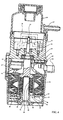
- FIG.3 is a cross sectional view taken along the axis of the rotating electrical machine and showing the associated hydraulic pump driven thereby.
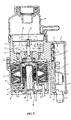
- FIG. 4 is a cross sectional view, in part similar to FIG. 3 and shows another embodiment of the invention.
- FIG. 5 is a cross sectional view, in part similar to FIGS. 3 and 4, and shows a third embodiment of the invention.
- FIG. 6 is a partial cross sectional view, in part similar to FIGS. 3, 4 and 5, and shows a fourth embodiment of the invention.
- FIG.7 is a partial cross sectional view, in part similar to FIGS. 3-6, and shows a fifth embodiment of the invention.
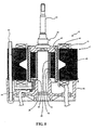
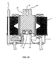
- FIG. 8. is a partial cross sectional view, in part similar to FIGS. 3-7, and shows a sixth embodiment of the invention.
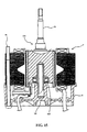
- FIG. 9 is a cross sectional view, in part similar to FIGS. 3-8, and shows a seventh embodiment of the invention.
- FIG. 10 is an end elevational view of the rotor shaft in this embodiment.
- FIG.11 is a cross sectional view, in part similar to FIGS. 3-8, and shows an eighth embodiment of the invention.
- FIG. 12 is a cross sectional view, in part similar to FIGS. 3-8 and 11, and shows a ninth embodiment of the invention.
- FIG. 13 is a partial cross sectional view, in part similar to FIGS. 3-8, 11 and 12, and shows a tenth embodiment of the invention.
- FIG. 14 is a partial cross sectional view, in part similar to FIGS. 3-8 and 11-13, and shows an eleventh embodiment of the invention.
- FIG. 15 is partial cross sectional view, in part similar to FIGS. 3-8 and 11-14, and shows a twelfth embodiment of the invention.
- FIG. 16 is a partial cross sectional view, in part similar to FIGS. 3-8 and 11-15, and shows a thirteenth embodiment of the invention.
- FIG. 17 is a partial cross sectional view, in part similar to FIGS. 3-8 and 11-16, and shows an fourteenth embodiment of the invention.
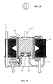
- FIG. 18 is a partial cross sectional view, in part similar to FIGS. 3-8 and 11-1 7, and shows an fifteenth embodiment of the invention.
- FIG. 19 is a partial cross sectional view, in part similar to FIGS. 3-8 and 11-18, and shows a sixteenth embodiment of the invention.
- FIG. 20 is an end elevational view of the rotor shaft of this embodiment.
- FIG. 1 shows a typical type of environment in which the invention can be utilized.
- a rotating electrical machine in the form of a brushless DC motor, which drives another load in the form of a hydraulic pump for utilization in an automotive power steering system.
- the combined assembly is indicated generally by the reference numeral 21 that includes the brushless DC motor 22 having a main motor housing to be described in more detail by reference later to Fig. 3 and an end closure 23 therefore which forms a bearing for the rotor of the electric motor, as will become apparent.
- a hydraulic pump to be described in more detail by reference to Fig. 3, is contained in substantial part in the end closure 23.
- a further closure member 24 encloses the hydraulic pump, which in turn, supplies hydraulic fluid from a reservoir formed therein for power assist to a hydraulic power steering mechanism, indicated generally by the reference numeral 25.
- the power steering mechanism 25 provides assist power to the gear mechanism that couples a vehicle steering wheel 26 to a steering rack 27.
- the steering rack 27 is mechanically coupled by means of tie rods 28 to the steering links of the vehicle.
- the torque of the electric driving motor 22 formed in part by the main motor housing is controlled by means of a controller, indicated generally by the reference numeral 29.
- the controller 29 that receives certain vehicle inputs so as to determine the amount of assist power that will be generated by the hydraulic pump in the end closure 23.
- the system can include a sensor 31 which senses the rotational angle of the steering wheel 26, a vehicle speed sensor, indicated generally by the reference numeral 32 and which inputs a signal indicative of the vehicle speed and an engine speed sensor 33 that inputs a signal indicative of the speed of rotation of the driving engine.
- the amount of power assist that would be optimal for the steering under various conditions. For example, if the vehicle is traveling at a load speed and the steering angle sensors senses large steering inputs, it can be assumed that the vehicle is being parked and greater assist may be necessary. This also can be determined by low vehicle engine speed, which indicates that the vehicle is in the parking mode.
- the specific control strategy that is employed forms no part of the invention and, as should be apparent from the foregoing description, the invention can be utilized in other applications and also in applications where rather than employing an electric motor the system employs an electrical generator, which may preferably be of the brushless DC type and which is driven by another form of prime mover and specifically a rotating shaft thereof.
- FIG. 2 this illustrates in more detail the assembly 21 and which includes three major components all contained within a basic common housing assembly. These include the housing of the main motor housing assembly 22 on to which is assembled an end closure 23 which, in turn, contains a reversible hydraulic pump 34. This pump 34 draws fluid from a reservoir contained within the further closure member 24.
- FIG. 3 is a cross sectional view of this assembly.
- the DC brushless reversible electric motor 22 includes a housing assembly that is comprised of a main housing piece 35 which had a generally cylindrical configuration and which is preferably formed from a high strength, lightweight material such as aluminum alloy or the like.
- the lower end of the main housing 35 is closed by an integral end closure 36 formed therewith.
- This end closure 36 has a boss portion 37 that receives a hardened steel, rotor support shaft 38, which extends into the cylindrical portion of the housing 35.
- This passes through a bore formed in a rotor assembly, indicated generally by the reference numeral 39. More specifically, this bore is comprised of an oil impregnated bearing 41 that is pressed or otherwise fitted into a bore 42 formed in the rotor assembly 39.
- the rotor assembly 39 is preferably formed from laminated electromagnetic steel plates on to which permanent magnets 43 are bonded at spaced intervals around the circumference.
- the magnets 43 are preferably formed from a magnetic material such as alnico, ferrite, neodymium-iron-boron or like materials.
- the magnets 43 are magnetized so that the polarity changes alternately in the circumferential direction and may be formed by either cylindrical shaped magnets or rectangular plate-like magnets bonded in side by side relation to the center axis.
- the outside surface of the rotor assembly 39 is preferably protected by a coating for rust proofing and to contain the plates by a suitable molded resin such as PPS (polyphenylene sulfide manufactured by DOW Chemicals). This is preferably for protection of the magnets 43.
- an armature assembly Positioned within the housing portion 35 radially outwardly of the outer surface of the permanent magnets 43 of the rotor assembly 39 is an armature assembly comprised of a three-phase field magnet coil, indicated at 44. This is comprised of a laminated core 45. The coil windings 44 are wound around insulating bobbins 46 surrounding the core poles to form the armature assembly, indicated generally by the reference numeral 47.
- a plurality of sensors specifically Hall-type sensors indicated by the reference numeral 48 which are mounted on a sensor plate 49 and which extend axially inwardly of the radial inner periphery of the magnets 43.
- These magnets 43 therefore extend axially beyond the core plates 45 so as to provide a very compact assembly.
- Electrical conductors 51 and 52 pass through the integral end closure 36 for receipt of the electric power.
- the controller assembly is suitably mounted externally of the motor assembly 22. Other control mounting arrangements are shown in Figs. 4 and 5.
- the end closure 23 has an integral wall portion 53 that receives an anti-friction bearing 54 that is received on a shoulder formed on the rotor assembly 39 at one end of a driving shaft portion 55 thereof.
- This shaft portion 55 extends into a cavity 56 formed in the end closure 23 for the motor assembly 22.
- the hydraulic pump 34 is received in this cavity 56 and thus, is contained and closed by the further closure member 24.
- the hydraulic fittings one of which is shown in this figure and identified by the reference numeral 57, are provided for transmitting the fluid under pressure to the hydraulic steering control mechanism 25 shown in FIG. 1.
- the rotor 39 can be mounted in the housing piece 35 and when the armature plates 45 and complete armature assembly 47 are in position. Then, the end closure 23 can be placed into position with the hydraulic pump 34 mounted therein into driving relationship with the shaft portion 55.
- this arrangement permits the use of conventional type pumps, which do not have to be specially designed so as to cooperate with the specific form of electric motor employed.
- FIG. 4 shows another embodiment of the invention, which is generally similar to the embodiment thus far described and particularly to the construction as shown in FIG. 3. Therefore, where components of this embodiment are the same as that previously described, they will be identified by the same reference numerals and will be described again only insofar as is necessary to understand the construction and operation of this embodiment.
- a controller assembly indicated generally by the reference numeral 61, is provided within the combined housing assembly 21.
- This controller assembly 61 is comprised of a further housing piece 62, which is sandwiched between the cylindrical portion of the motor housing 35 and the end closure 23 therefore.
- this housing 62 Contained within this housing 62 is the control mechanism for the motor assembly 22 and this includes a bridge circuit that is comprised of, for example, six FETS 63 that are mounted on a support plate 64 in close thermal contact with the metal housing pieces 23 and 35 so as to rapidly dissipate heat therefrom.
- a bridge circuit that is comprised of, for example, six FETS 63 that are mounted on a support plate 64 in close thermal contact with the metal housing pieces 23 and 35 so as to rapidly dissipate heat therefrom.
- other control circuit components such as an IC element 65 are mounted on the plate 64 and are connected to a external connector 66 so that the electrically connections can be made externally without the need to pass any conductors therethrough as with the preceding described embodiment.
- this embodiment is the same as that previously described and it has the same advantages and features as previously set forth.
- FIG. 5 shows another embodiment of the invention, which is quite similar to those already, described but in this embodiment, a control assembly, indicated generally by the reference numeral 71, is mounted on the side of the end closure 23 of the assembly so as to shorten the overall length.
- This control assembly 71 cooperates with a mounting boss 72 formed on the closure member 23 and also supports six FETS 73 on an insulating plate or circuit board 74 on which other electrical components are mounted such as an IC element 75.
- the controller 71 is comprised of an elongated housing member 76 that defines the cavity 77 in which these components are located and which cavity is closed by a closure plate 78 for servicing purposes.
- An end mounted electrical connector 79 provides for the electrical connections for the control.
- the first embodiment shown in FIG. 6 basically is the same as the electric motor portion of those embodiments already described. Therefore, it is believed that further description of this embodiment is not necessary to permit those skilled in the art to practice the invention and common parts are identified by the same reference numerals.
- FIG. 7 illustrates another embodiment that further reduces the costs and simplifies the overall construction in that the armature assembly 47 of the motor assembly 22 is not totally covered by the end closure and housing portion 35.
- the axial length of this portion 35 is reduced and threaded fasteners 81 pass through the laminated plates of the armature core 45 and can be fasten to the end closure 23.
- the end closure 23 need not be extended downwardly so as to enclose the outer periphery of the armature plates 45 that are not covered by the portion 35. This reduces the cost and weight of the overall construction.
- FIG. 8 illustrates another embodiment of motor assembly, which is basically the same as that shown in FIG. 7.
- the laminations of the rotor have in their center a steel plate sleeve 91 into which the oil impregnated bearing 41 is pressed fit. Because of the fact that the steel sleeve 91 has a smooth surface as opposed to the rougher surface provided by the laminations of the core 45, the oil impregnated bearing 41 can be more easily inserted without the likelihood of damage occurring to it.
- FIGS. 9 and 10 show another embodiment of this invention and this embodiment is similar to those of FIGS. 7 and 8. Therefore parts which are the same are identified by the same reference numerals.
- rotor indicated generally by the reference numeral 101, has a solid rather than a laminated cylindrical body 102.
- the permanent magnets 43 are bonded to the outer circumference of this body 102.
- the extended portion of the rotor body 102 is formed with a rectangular shaped opening 103 so that the driven load will have a tongue shape that fits into this opening so as to establish a driving relationship, thus eliminating the need for keys or splines.
- the structure is basically the same as that shown in FIG. 9, however, in this embodiment the main housing 35 is longer and extends up to the top of the structure much like the embodiments of FIGS. 3-5 and 6.
- FIG. 12 is like the embodiment of FIGS. 9 and 10, however, this embodiment employs a laminated core 111 for main portion of the rotor, indicated generally by the reference numeral 112. Where other components are the same as those previously described, they have been identified by the same reference numerals.
- FIG. 13 shows another embodiment having a housing construction like those of FIGS. 3-5,6 and 11 but instead of the larger diameter, longer steel post, there is provided a pin like support post 121 that is received in the end plate opening formed by the boss portion 37 and which carries a ball bearing 122 on its outer periphery. This ball bearing is pressed fitted into the rotor body, which, in this embodiment, is solid, and the rotor is indicated by the reference numeral 123. This provides a longer life.
- FIG. 14 shows another embodiment that is like that of the embodiment of FIG. 13, however, in this embodiment the stator case is shorter and only engages one end of the stator like the embodiments of FIGS. 7, 8, 9 and 10, and 12.
- FIGS. 15 and 16 illustrate different embodiments of the invention wherein rather than using a solid pin as in the embodiments of FIGS. 13 and 14, the anti-friction ball bearing 122 is carried on a tubular steel rod 131.
- the end of the rotor shaft indicated by the reference numeral 132, is provided with a rectangular projection that can fit into a similarly shaped female key opening formed in the associated pump.
- FIGS. 17-19 shows another type of bearing arrangement for the rotor.
- the integral end closure 36 of the motor housing 35 is formed with an upstanding cylindrical projection 141 having a smaller diameter part 142 on which the ball bearing 122 is mounted.
- FIG. 17 shows a conventional type shaft arrangement for the rotor like shown in FIGS. 2-4, 5-8, and 17, while FIG. 18 shows a slotted arrangement as in FIGS. 9 and 10, 11 and 12.
- FIG. 19 shows a tongue like shaft end as in FIG. 16 for coupling to the associated hydraulic pump.
Landscapes
- Engineering & Computer Science (AREA)
- Power Engineering (AREA)
- Microelectronics & Electronic Packaging (AREA)
- Chemical & Material Sciences (AREA)
- Combustion & Propulsion (AREA)
- Transportation (AREA)
- Mechanical Engineering (AREA)
- Motor Or Generator Frames (AREA)
- Connection Of Motors, Electrical Generators, Mechanical Devices, And The Like (AREA)
Applications Claiming Priority (4)
| Application Number | Priority Date | Filing Date | Title |
|---|---|---|---|
| JP2000108258 | 2000-04-10 | ||
| JP2000108258A JP2001298903A (ja) | 2000-04-10 | 2000-04-10 | ブラシレスdcモータ |
| US681430 | 2001-04-03 | ||
| US09/681,430 US20010033113A1 (en) | 2000-04-10 | 2001-04-03 | Rotating electrical machine |
Publications (2)
| Publication Number | Publication Date |
|---|---|
| EP1146625A2 true EP1146625A2 (fr) | 2001-10-17 |
| EP1146625A3 EP1146625A3 (fr) | 2004-04-28 |
Family
ID=26589791
Family Applications (1)
| Application Number | Title | Priority Date | Filing Date |
|---|---|---|---|
| EP01108850A Withdrawn EP1146625A3 (fr) | 2000-04-10 | 2001-04-09 | Machine électrique tournante |
Country Status (3)
| Country | Link |
|---|---|
| EP (1) | EP1146625A3 (fr) |
| CN (1) | CN1326257A (fr) |
| TW (1) | TW525336B (fr) |
Cited By (4)
| Publication number | Priority date | Publication date | Assignee | Title |
|---|---|---|---|---|
| EP2701291A1 (fr) * | 2012-08-21 | 2014-02-26 | Pierburg Pump Technology GmbH | Pompe à fluide électrique pour véhicule automobile |
| WO2017036549A1 (fr) * | 2015-09-04 | 2017-03-09 | Pierburg Pump Technology Gmbh | Dispositif auxiliaire d'automobile à moteur d'entraînement électrique |
| WO2019081011A1 (fr) | 2017-10-25 | 2019-05-02 | Pierburg Pump Technology Gmbh | Pompe à fluide électrique de véhicule automobile |
| WO2022162599A1 (fr) * | 2021-01-29 | 2022-08-04 | Amer S.P.A. | Capuchon d'extrémité pour moteurs électriques, et unité de moteur comprenant un moteur électrique associé audit capuchon d'extrémité |
Families Citing this family (3)
| Publication number | Priority date | Publication date | Assignee | Title |
|---|---|---|---|---|
| JP3866237B2 (ja) * | 2003-10-06 | 2007-01-10 | 三菱電機株式会社 | 電動パワーステアリング用モータ |
| CN111315634B (zh) * | 2017-11-07 | 2022-07-29 | 欧尼贝耐电力股份公司 | 电动动力转向设备 |
| CN119190179B (zh) * | 2024-11-06 | 2025-06-27 | 滁州学院 | 一种具有能量回收和冗余安全功能的车辆多模式切换转向系统及控制方法 |
Family Cites Families (8)
| Publication number | Priority date | Publication date | Assignee | Title |
|---|---|---|---|---|
| US2501814A (en) * | 1948-09-03 | 1950-03-28 | George A Gillen | Electric motor |
| DE1191899B (de) * | 1962-09-14 | 1965-04-29 | Licentia Gmbh | Kleiner Elektromotor, insbesondere zum Antrieb von Tongeraeten |
| JPS56139052A (en) * | 1980-03-31 | 1981-10-30 | Matsushita Electric Works Ltd | Small-sized motor |
| US4438359A (en) * | 1982-04-14 | 1984-03-20 | Emerson Electric Co. | Dynamoelectric machine structure and method |
| US4992690A (en) * | 1988-10-07 | 1991-02-12 | Emerson Electric Co. | Combination motor endshield and pump housing |
| DE19627668A1 (de) * | 1996-07-10 | 1998-01-15 | Hydraulik Ring Gmbh | Antriebsvorrichtung, insbesondere als Lenkhilfe für Kraftfahrzeuge |
| DE19728802A1 (de) * | 1997-07-05 | 1999-01-07 | Itt Mfg Enterprises Inc | Lageranordnung für ein motorangetriebenes Aggregat |
| WO2000008338A1 (fr) * | 1998-08-06 | 2000-02-17 | Automotive Motion Technology Limited | Pompe entrainee par un moteur |
-
2001
- 2001-04-09 EP EP01108850A patent/EP1146625A3/fr not_active Withdrawn
- 2001-04-10 TW TW090108546A patent/TW525336B/zh not_active IP Right Cessation
- 2001-04-10 CN CN01119609A patent/CN1326257A/zh active Pending
Cited By (7)
| Publication number | Priority date | Publication date | Assignee | Title |
|---|---|---|---|---|
| EP2701291A1 (fr) * | 2012-08-21 | 2014-02-26 | Pierburg Pump Technology GmbH | Pompe à fluide électrique pour véhicule automobile |
| WO2017036549A1 (fr) * | 2015-09-04 | 2017-03-09 | Pierburg Pump Technology Gmbh | Dispositif auxiliaire d'automobile à moteur d'entraînement électrique |
| US10778073B2 (en) | 2015-09-04 | 2020-09-15 | Pierburg Pump Technology Gmbh | Automotive auxiliary device with electric drive motor |
| WO2019081011A1 (fr) | 2017-10-25 | 2019-05-02 | Pierburg Pump Technology Gmbh | Pompe à fluide électrique de véhicule automobile |
| US11462971B2 (en) | 2017-10-25 | 2022-10-04 | Pierburg Pump Technology Gmbh | Electric fluid pump for a motor vehicle |
| WO2022162599A1 (fr) * | 2021-01-29 | 2022-08-04 | Amer S.P.A. | Capuchon d'extrémité pour moteurs électriques, et unité de moteur comprenant un moteur électrique associé audit capuchon d'extrémité |
| US12401251B2 (en) | 2021-01-29 | 2025-08-26 | Amer S.P.A. | End cap for electric motors, and motor unit comprising an electric motor associated with said end cap |
Also Published As
| Publication number | Publication date |
|---|---|
| CN1326257A (zh) | 2001-12-12 |
| TW525336B (en) | 2003-03-21 |
| EP1146625A3 (fr) | 2004-04-28 |
Similar Documents
| Publication | Publication Date | Title |
|---|---|---|
| US20010033113A1 (en) | Rotating electrical machine | |
| KR100508315B1 (ko) | 개선된 고속 전기 모터 | |
| KR100998542B1 (ko) | 보조 기계 구동 장치 | |
| US7663282B2 (en) | Traction drive for elevator | |
| US7863789B2 (en) | Brushless permanent magnet motor/generator with axial rotor decoupling to eliminate magnet induced torque losses | |
| US10855121B2 (en) | Rotary electric machine, electric power steering device, and method of manufacturing a rotary electric machine | |
| US8739919B2 (en) | Motor and electric power steering system | |
| EP1850455A2 (fr) | Rotor de moteur électrique pour simplifier le procédé de fabrication et moteur électrique doté de celui-ci | |
| EP1182766B1 (fr) | Moteur sans balais | |
| JP2005517373A (ja) | 電気モータおよびそれを動力源とする車両 | |
| JP2015159706A (ja) | 電動機、電動パワーステアリング装置及び車両 | |
| US20160297470A1 (en) | Drive device and electric power steering apparatus | |
| EP1650851B1 (fr) | Moteur asynchrone monophasé | |
| EP1146625A2 (fr) | Machine électrique tournante | |
| JP2007531489A (ja) | 電動アクチュエータ | |
| US20130181563A1 (en) | Electric Motor | |
| CA1237184A (fr) | Machine electrique a aimant permanent de ferrite, et son emploi dans des dispositifs de traction pour vehicules | |
| WO2002020293A3 (fr) | Servo-direction electrique sans ondulation de couple | |
| EP1257042A3 (fr) | Motor suspendu magnétiquement | |
| CN101258662A (zh) | 电动动力转向装置用马达 | |
| EP1691475A3 (fr) | Servo-direction électrique sans ondulation de couple | |
| JP2006280088A (ja) | ブラシレスモータ | |
| KR102224049B1 (ko) | 차량용 인휠 모터 | |
| CN223079827U (zh) | 一种外转子辊筒电机及电辊筒 | |
| JP2001213336A (ja) | 電動油圧パワーステアリング装置 |
Legal Events
| Date | Code | Title | Description |
|---|---|---|---|
| PUAI | Public reference made under article 153(3) epc to a published international application that has entered the european phase |
Free format text: ORIGINAL CODE: 0009012 |
|
| AK | Designated contracting states |
Kind code of ref document: A2 Designated state(s): AT BE CH CY DE DK ES FI FR GB GR IE IT LI LU MC NL PT SE TR |
|
| AX | Request for extension of the european patent |
Free format text: AL;LT;LV;MK;RO;SI |
|
| PUAL | Search report despatched |
Free format text: ORIGINAL CODE: 0009013 |
|
| AK | Designated contracting states |
Kind code of ref document: A3 Designated state(s): AT BE CH CY DE DK ES FI FR GB GR IE IT LI LU MC NL PT SE TR |
|
| AX | Request for extension of the european patent |
Extension state: AL LT LV MK RO SI |
|
| RIC1 | Information provided on ipc code assigned before grant |
Ipc: 7F 04D 29/04 B Ipc: 7B 62D 5/06 B Ipc: 7H 02K 7/14 A |
|
| 17P | Request for examination filed |
Effective date: 20041018 |
|
| 17Q | First examination report despatched |
Effective date: 20041115 |
|
| AKX | Designation fees paid |
Designated state(s): DE FR GB |
|
| STAA | Information on the status of an ep patent application or granted ep patent |
Free format text: STATUS: THE APPLICATION IS DEEMED TO BE WITHDRAWN |
|
| 18D | Application deemed to be withdrawn |
Effective date: 20051206 |