EP1147383B2 - Dispositif de pesage pour vehicules sur rails - Google Patents
Dispositif de pesage pour vehicules sur rails Download PDFInfo
- Publication number
- EP1147383B2 EP1147383B2 EP99963566A EP99963566A EP1147383B2 EP 1147383 B2 EP1147383 B2 EP 1147383B2 EP 99963566 A EP99963566 A EP 99963566A EP 99963566 A EP99963566 A EP 99963566A EP 1147383 B2 EP1147383 B2 EP 1147383B2
- Authority
- EP
- European Patent Office
- Prior art keywords
- weighing
- rail
- load
- weighing device
- load measuring
- Prior art date
- Legal status (The legal status is an assumption and is not a legal conclusion. Google has not performed a legal analysis and makes no representation as to the accuracy of the status listed.)
- Expired - Lifetime
Links
Images

Classifications
-
- G—PHYSICS
- G01—MEASURING; TESTING
- G01G—WEIGHING
- G01G19/00—Weighing apparatus or methods adapted for special purposes not provided for in the preceding groups
- G01G19/02—Weighing apparatus or methods adapted for special purposes not provided for in the preceding groups for weighing wheeled or rolling bodies, e.g. vehicles
- G01G19/04—Weighing apparatus or methods adapted for special purposes not provided for in the preceding groups for weighing wheeled or rolling bodies, e.g. vehicles for weighing railway vehicles
- G01G19/045—Weighing apparatus or methods adapted for special purposes not provided for in the preceding groups for weighing wheeled or rolling bodies, e.g. vehicles for weighing railway vehicles for weighing railway vehicles in motion
- G01G19/047—Weighing apparatus or methods adapted for special purposes not provided for in the preceding groups for weighing wheeled or rolling bodies, e.g. vehicles for weighing railway vehicles for weighing railway vehicles in motion using electrical weight-sensitive devices
Definitions
- the invention relates to a weighing device for rail vehicles according to the preamble of patent claim 1.
- the weighing of rail vehicles was carried out years ago mostly with the help of weighbridges, in which the total weight of a single railroad car was determined statically.
- the rails on the weighing platform were separated from the rails of the track section by gaps in front of and behind the weighbridge.
- the weighing platform was stored on at least four load cells and supported against a foundation. For this purpose, weighing platforms in wagon length were necessary, which required a very elaborate bridge substructure made of concrete or steel components.
- a weighing device for rail vehicles for static and dynamic weight determination in which between the rails and a cross member load cells are arranged, through which the axle load of a passing railroad cars can be determined.
- the rails are each provided with three consecutively arranged recesses in the rail base and web, so that the rails are articulated on the load cells. Due to this articulated support of the two sections of each rail a complex foundation or a frame construction is required in each case, which receives the axle against the ground.
- the cross members obviously consist of double T-shaped steel girders, which can not be installed in the rail network without major modifications.
- the invention is therefore an object of the invention to provide a weighing device for rail vehicles, which requires only minor structural changes in the rail network and with the still high accuracy can be achieved.
- ballast bonding technology in which the stabilization of the ballast bed is achieved with an epoxy resin.
- the epoxy resin is sprayed with a hardener on the ballast bed, which penetrates by its viscosity in this and the contact surfaces of the ballast stones glued together.
- This ballast bonding technique is used in track construction but mainly only to protect against ballast and to steadily increase the stabilization at transition areas between ballast track and fixed carriageway. In any case, it is not known to provide ballast bonding for supporting a weighing platform.
- the invention has the advantage that both static and dynamic weight measurement of rail vehicles is made possible by the force measurement by means of weighing thresholds.
- a measuring device can be calibrated in a simple manner for a dynamic weight determination, without the need for a far-removed weighbridge would have to be used.
- the entire weighing device consists of only one or more weighing sleepers that can be installed in the normal ballast bed like other sleepers. This eliminates the necessary transport problems of long track pieces or concrete or steel components, as they are otherwise necessary for static weighbridges.
- the invention has the advantage that the entire measuring technique can be poured in today's conventional concrete sleepers in the manufacturing process without much extra effort.
- variable bridge lengths can then be assembled in a simple manner, for example, a weighing threshold for a single axis or eight weighing sleepers for a three-axle bogie or forty weighing sleepers for a complete high-precision wagon weighing.
- weighing sleepers in particular also the ease of service is advantageous because in case of defects in the sensor in the worst case, the whole weighing threshold must be replaced as any other track threshold.
- the load cells in the weighing sleepers are also executable that These are individually interchangeable, because they are always installed from above or from the side and are so easily accessible.
- the weighing sleeper is glued in a glued ballast bed, with no bridge construction is more necessary, as otherwise in concrete or steel bridges.
- a stabilization of the ground stiffness jumps can be avoided as in concrete or steel bridges, as in a defined arrival and departure a continuous stiffening increase or decrease takes place, so that the track-related suggestions are minimized to Waggonstörschwingungen during the weighing process.
- the force bypass effect can be corrected or reduced by the uninterruptible rail track.
- rail switches are also unnecessary at the same time, which are otherwise necessary for determining the wagon type in the driving consideration.
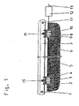
- Fig. 1 the drawing is a weighing device for rail vehicles with two glued in Weighing waves 2, 8 shown as a cross member in a bonded gravel bed 6, wherein at the beginning and at the end of the measuring section in each rail each Meßauge 1, 11 is provided as shear stress sensor for Kraftnebenschluß correction in the region of the threshold compartment ,
- the two weighing sleepers 2, 8 are arranged in a ballast bed 6, as is customary as a rail track in railway construction.
- the two weighing sleepers 2, 8 as other thresholds are arranged transversely to the direction of travel parallel to each other, these being surrounded by the stones of the ballast bed 6 performing.
- the ballast stones are sprayed with a two-component adhesive based on epoxy resin with hardener, so that a ballast bond is formed by the liquid, penetrating into the ballast bed 6 adhesive. In this case, there is also an adhesion of the weighing sleepers 2, 8 with the ballast stones.
- ballast bonding has hitherto been customary for track construction work to protect against ballast on high-speed lines and for stabilization at transition areas between ballast lanes and fixed carriageways. In many cases, such a ballast bond is already provided for stabilization at points and road edges in stations.
- a ballast bond has proven to be advantageous, which is about a wagon length before and a wagon length after the or the weighing sleepers 2, 8 is made and should take place depending on the load to a depth of 0.5 m.
- the gravel stones stick together at their points of contact or edges, so that a solid stabilized ballast bed 6 is formed.
- the stabilization of the ballast bed 6 is dependent on the amount and the penetration depth of the two-component adhesive.
- different degrees of stabilization of the ballast bed can be produced, so that in particular a steady increase in the stiffening or hardening at the beginning and / or a steady reduction at the end of the weighing device is advantageous.
- this stabilized ballast bed 6 the weighing sleepers 2, 8 glued to this, so that a frictional connection between the weighing sleepers 2, 8 and the ballast bed 6 is formed.
- the weighing sleepers 2, 8 are designed essentially like normal sleepers only with the difference that the force measuring devices are integrated in them.
- the weighing sleepers 2, 8 can also be manufactured from other materials suitable for the production of sleepers.
- the provided in the recesses 4, 9 force measuring devices 4, 10 are provided on its upper side with connecting elements which establish a firm connection with the overlying rail 7.
- connecting elements which establish a firm connection with the overlying rail 7.
- clamp connections 15, 14 are preferably provided, as are also customary for connecting the rails 7 to the other sleepers.
- other connecting elements may be provided if this is necessary or advantageous due to the construction of the force measuring device 3, 10.
- the rails 7 are formed without interruption in the weighing device and represent common rails.
- the entire weighing device is preferably formed from six to eight Weighing waves 2, 8, which are suitable for weighing railway cars or other rail vehicles with up to three-axle bogies and a test section of 4 to 5 m. In the described embodiment, however, only two weighing sleepers 2, 8 are shown for reasons of clarity. For weight determination of rail vehicles with only two axes but weighing devices with only one weighing threshold 2, 8 would be sufficient.
- a so-called measuring eye 11 is provided as a shear stress sensor in the neutral fiber of each rail 7 at the beginning and / or at the end of the measuring path in the middle between the first and last weighing threshold 2, 8 and the adjacent threshold.
- a measuring eye 11 in a simple manner, the shear stress is measured, which occurs when rolling over a vehicle axle in the neutral fiber of each rail 7.
- Meßaugen 11 have proved to be advantageous because they are designed as a circular pick-up unit with strain gauges.
- These measuring eyes 11 can advantageously be fastened in a bore in the neutral fiber of each rail in a simple manner.
- Such Schubhardsaufêt 11 but can also be designed differently, for example, they can also be applied directly to the rail web.
- both the signals of shear stress sensors 11, 1 and of the force measuring devices 3, 10 of each weighing threshold 2, 8 are fed to a central evaluation device 12.
- the weighing device can first be statically calibrated. In this case, the detection of the location-dependent force bypass effect by means of the shear stress sensors 1, 11 takes place.
- a reference mass or the test device is placed at different positions of the test section. Alternatively, this process can also be carried out automatically with moving reference mass.
- the correction functions derived from the shear stress measurements of the calibration process are stored.
- the static weights can be determined for unknown masses.
- the weighing device can be dynamically calibrated.
- the determined dynamic correction functions are also stored in the central evaluation device 12. It is thus possible to calibrate such a weighing device in a simple manner statically and dynamically with known reference masses or a testing device, as well as other unknown masses.
- the weighing signal calibrated in the central evaluation device 12 can be queried or displayed at its output for further processing or for display by another device.
- the force bypass effect is so far reduced by a recess in the rail foot and web that their influence on the measurement result is only slightly.
- a recess in the rail base and web is incorporated before the first weighing sleeper 8, but does not interrupt the drive-over part, so that an articulated coupling is formed.
- the force bypass effect is the lower, the farther this joint is removed bearing free from the first measuring threshold 8 and the less bending stress is transmitted through the joint.
- a certain shear stress must not be exceeded in this joint so as not to be damaged when passing over a permissible load, a certain force bypass effect can not be prevented.
- the measurement result can be particularly improved by the fact that both at the beginning and at the end of the test section, a recess and a shear stress measurement is made.
- the shear stress sensors 1, 11 are used simultaneously as a rail switch. For this purpose, with the aid of predetermined center distances of known rail vehicles by the central evaluation device 12, respectively the beginning and the end of a vehicle traveling over are determined. From the known and measured center distances, the vehicle weight can then be determined in the evaluation device 12.
- a force measuring device 3 is shown as a sectional view of a section of a weighing threshold 2 in detail.
- the same reference numerals have been used as they are for functionally identical parts of Fig. 1 the drawing were used.
- the Wägeschwelle 2 contains a force measuring device 3, which is fixedly disposed in a cast-housing 22. Conveniently, this housing unit 22 reinforcing elements 23 which ensure a permanent connection with the reinforced concrete sleepers 2.
- a force measuring device 3 is provided as a load cell, which is arranged below the rail 7.
- This load cell 3 includes a force introduction part 18, a deformation body 17 to which strain gauges 20 are applied, and a force extraction part 21 fixedly secured to the housing 22.
- This load cell 3 is S-shaped, so that the force introduction parts 18 and the force extraction parts 21 are simultaneously formed as force return elements.
- the force introduction 18 and the Kraftaus effetselement 21 are separated by horizontal slots 16, 26 from the deformation part 17.
- the deformation part 17 contains in the center two opposing horizontal blind holes 19, so that between the two holes a vertical deformation surface remains, to which the strain gauges 20 are applied. These generate a signal proportional to the weight on the rail 7.
- clamping elements 14 between which the rail 7 extends transversely to the load cell 3 and is firmly screwed to this.
- load cells 3 are provided with force return elements 18, 21 advantageously, since in these the measured force is largely independent of the force application point, so that focal shifts on the rail 7 have no influence on the measurement result. It is therefore advantageously also load beam with force return elements used, the rail 7 would be attached to an upper force return element, while a lower force return element would be firmly connected to the housing 22.
- the force measuring devices 3, 10 may also be designed so that they are secured to the housing 22 by a detachable connection. In particular, this can advantageously screw connections are provided so that the individual measuring devices 3, 10 can be replaced in case of damage after lifting the rail 7 individually from above.
- the housing 22 of the force measuring devices 3, 10 could also be brought up to the threshold end and be provided with a detachable side part, so that the force measuring devices 3, 10 could also be advantageously laterally replaced without having to raise the rail 7.
- a horizontal cable channel 25 is provided, in which the wiring to the strain gauges 20 and the measuring eyes 1, 11 is guided damage safely.
- the cable channel 25 terminates in the middle of the weighing threshold 2, 8 in a Verschaltungsaussparung 24, in addition, electrical circuits are arranged, which are used for power supply and for distance-independent Meßsignalumwandlung (A / D converter).
- a tubular connecting channel 5 is provided in the rail direction, through which the weighing sleepers 2, 8 are electrically connected to each other and to a central evaluation device 12.
Landscapes
- Physics & Mathematics (AREA)
- General Physics & Mathematics (AREA)
- Force Measurement Appropriate To Specific Purposes (AREA)
- Machines For Laying And Maintaining Railways (AREA)
- Electric Propulsion And Braking For Vehicles (AREA)
Claims (16)
- Dispositif de pesage pour véhicules sur rails, où, entre non moins d'un rail de roulement et non moins d'une traverse, est disposé un capteur dynamométrique, qui forme une section mesurée émettant un signal proportionnel à la charge exercée sur le rail, caractérisé en ce que en amont du premier et en aval du dernier capteur dynamométrique (3, 10) de la section mesurée du rail de roulement (7), au moins un capteur de contrainte au cisaillement additionnel (1, 11) est placé sur l'axe neutre du rail (7) pour déterminer le couplage de dérivation de force, dont les signaux de mesure servent à la correction du couplage de dérivation de force.
- Dispositif de pesée selon l'une des revendications 1, caractérisé en ce qu'une fonction de rectification dépendant du lieu est formée et mémorisée dans un dispositif d'analyse (12) sur la base de la mesure de la contrainte au cisaillement et d'un calibrage statique, laquelle fonction sert à la prise en considération du couplage de dérivation de force pendant la pesée dynamique.
- Dispositif de pesée selon l'une des revendications 1 ou 2 , caractérisé en ce que des cellules de pesage (3) sont prévues comme dispositifs dynamométrique (3, 10), dont les signaux de pesée sont reliés entre eux de telle sorte que le poids des véhicules sur rails ou de parties de ceux-ci peut être calculé à partir des signaux de mesure.
- Dispositif de pesée selon l'une quelconque des revendications précédentes, caractérisé en ce que les signaux d'au moins un capteur de contrainte au cisaillement (11) servent en même temps de commutateurs de rails, à partir desquels un début et une fin de wagon ou un début ou une fin de bogie sont déterminés dans le dispositif d'analyse (12) et à l'aide d'entraxes des essieux prédéfinis.
- Dispositif de pesée selon l'une quelconque des revendications précédentes, caractérisé en ce que le capteur de contrainte au cisaillement (11) est réalisé comme oeil de mesure qui est agencé dans un perçage du rail (7) ou formé par des jauges d'allongement appliquées directement.
- Dispositif de pesée selon l'une quelconque des revendications précédentes, caractérisé en ce qu'il est prévu dans le patin du rail, au moins avant le premier dispositif dynamométrique (3, 10), un évidement ouvert vers le bas verticalement ou obliquement, qui relie le rail de roulement (7) de façon articulée avec le ou les dispositifs dynamométriques (3, 10).
- Dispositif de pesée selon l'une quelconque des revendications précédentes, caractérisé en ce qu'il est prévu dans le patin du rail, au moins avant le premier et/ou le dernier dispositif dynamométrique (3, 10), un évidement ouvert vers le bas verticalement ou obliquement, qui relie le rail de roulement (7) de façon articulée avec le ou les dispositifs dynamométriques (3, 10).
- Dispositif de pesée selon l'une quelconque des revendications précédentes, caractérisé en ce que le dispositif dynamométrique (3, 10) est agencé pour chaque rail (7) entre le rail concerné (7) et une traverse.
- Dispositif de pesée selon l'une quelconque des revendications précédentes, caractérisé en ce que la poutre transversale est réalisée comme traverse de pesée (2, 8), dans laquelle les dispositifs dynamoétrique (3, 10) sont intégrés et prennent appui sur une surface stabilisée.
- Dispositif de pesée selon l'une quelconque des revendications précédentes, caractérisé en ce que le dispositif de pesée est constitué d'au moins une traverse de pesée (2, 8) ou d'une pluralité de traverses de pesée (2, 8).
- Dispositif de pesée selon l'une quelconque des revendications précédentes, caractérisé en ce que la traverse de pesée (2, 8) est constituée de béton armé ou d'un autre matériau prévu pour la fabrication de traverses.
- Dispositif de pesée selon l'une quelconque des revendications précédentes, caractérisé en ce que chaque traverse de pesée (2, 8) comprend au moins deux évidements (4, 9) pour l'intégration des dispositifs dynamoùétrique (3, 10), qui sont prévus en dessous de l'assise du rail.
- Dispositif de pesée selon l'une quelconque des revendications précédentes, caractérisé en ce que dans les évidements (4, 9) sont agencés des dispositifs dynamométriques (3, 10) dont la partie d'arrivée de force (18) est reliée avec le rail (7) et la partie de sortie de force (21) avec la traverse (2, 8) par force et par moment.
- Dispositif de pesée selon l'une quelconque des revendications précédentes, caractérisé en ce que le dispositif dynamométrique (3, 10) est fixé dans un élément de logement fixe (22) qui est soudé ou relié de façon rigide par d'autres moyens d'assemblage avec la traverses (2, 8).
- Dispositif de pesée selon l'une quelconque des revendications précédentes, caractérisé en ce que le dispositif dynamométrique (3, 10) est relié à l'élément de logement (22) par un assemblage démontable, l'élément de logement (22) disposant d'une partie de fermeture pouvant être enlevée sur le haut ou sur le côté, par laquelle le dispositif dynamoùétrique (3, 10) peut être remplacé.
- Dispositif de pesée selon l'une quelconque des revendications précédentes, caractérisé en ce que le dispositif dynamométrique (3, 10) est réalisé comme cellules de pesée des éléments de rétroaction de force (18,21).
Applications Claiming Priority (3)
| Application Number | Priority Date | Filing Date | Title |
|---|---|---|---|
| DE19861099A DE19861099A1 (de) | 1998-12-22 | 1998-12-22 | Wägevorrichtung für Schienenfahrzeuge |
| DE19861099 | 1998-12-22 | ||
| PCT/EP1999/010028 WO2000037900A1 (fr) | 1998-12-22 | 1999-12-17 | Dispositif de pesage pour vehicules sur rails |
Publications (3)
| Publication Number | Publication Date |
|---|---|
| EP1147383A1 EP1147383A1 (fr) | 2001-10-24 |
| EP1147383B1 EP1147383B1 (fr) | 2004-10-06 |
| EP1147383B2 true EP1147383B2 (fr) | 2010-09-08 |
Family
ID=7893296
Family Applications (1)
| Application Number | Title | Priority Date | Filing Date |
|---|---|---|---|
| EP99963566A Expired - Lifetime EP1147383B2 (fr) | 1998-12-22 | 1999-12-17 | Dispositif de pesage pour vehicules sur rails |
Country Status (5)
| Country | Link |
|---|---|
| EP (1) | EP1147383B2 (fr) |
| AT (1) | ATE278938T1 (fr) |
| AU (1) | AU1981500A (fr) |
| DE (1) | DE19859492A1 (fr) |
| WO (1) | WO2000037900A1 (fr) |
Families Citing this family (7)
| Publication number | Priority date | Publication date | Assignee | Title |
|---|---|---|---|---|
| DE10031092A1 (de) * | 2000-06-30 | 2002-01-10 | Schenck Process Gmbh | Wägevorrichtung für Schienenfahrzeuge |
| DE102004030742B4 (de) * | 2004-06-25 | 2006-06-01 | Schenck Process Gmbh | Verfahren zur Ermittlung von Referenzgewichten mit einer dynamischen Gleiswaage |
| CA2684677C (fr) * | 2007-04-26 | 2016-04-19 | Digi Sens Ag | Dispositif dynamique de pesage de dechets |
| FR2983812B1 (fr) * | 2011-12-09 | 2015-06-05 | Sateba Systeme Vagneux | Support en beton instrumente pour rails de voie ferree |
| CN105170930A (zh) * | 2015-08-27 | 2015-12-23 | 北京中远通科技有限公司 | 一种在线称重辊道 |
| AT522346B1 (de) | 2019-03-22 | 2020-11-15 | Getzner Werkstoffe Holding Gmbh | Eisenbahnfahrweg |
| CN113566941B (zh) * | 2021-08-24 | 2025-10-03 | 柳州市铁科科技有限责任公司 | 一种新型轨道称重结构 |
Citations (6)
| Publication number | Priority date | Publication date | Assignee | Title |
|---|---|---|---|---|
| EP0500971A1 (fr) † | 1991-02-25 | 1992-09-02 | Carl Schenck Ag | Méthode de pesage |
| US5205368A (en) † | 1990-07-26 | 1993-04-27 | Pfister Messtechnik Gmbh | Apparatus and method for weighing rail-supported vehicles |
| DE4444337A1 (de) † | 1994-12-14 | 1996-06-20 | Tron Suisse S A K | Vorrichtung für das fortlaufende Abwiegen von Fahrzeugen |
| DE4439342C2 (de) † | 1994-11-04 | 1997-02-20 | Deutsche Bahn Ag | Anordnung zur Ermittlung unrunder Räder von Eisenbahnfahrzeugen |
| JPH10185666A (ja) † | 1996-12-25 | 1998-07-14 | Unyusho Senpaku Gijutsu Kenkyusho | 地上側測定による鉄道車両の輪重・横圧の連続測定方法及びその装置 |
| WO2000023770A1 (fr) † | 1998-10-20 | 2000-04-27 | Pfister Waagen Gmbh | Bascule a wagons |
Family Cites Families (3)
| Publication number | Priority date | Publication date | Assignee | Title |
|---|---|---|---|---|
| DE4014529A1 (de) * | 1990-05-07 | 1991-11-14 | Koch Marmorit Gmbh | Verfahren zum vergroessern des querverschiebewiderstands von eisenbahnschwellen auf einem schotterbett |
| US5224561A (en) * | 1992-04-07 | 1993-07-06 | Flintab Ab | Weigh-rail |
| DE4214889A1 (de) * | 1992-05-07 | 1993-11-11 | Koch Marmorit Gmbh | Verfahren zur Sanierung und Stabilisierung von Eisenbahngleisen |
-
1998
- 1998-12-22 DE DE19859492A patent/DE19859492A1/de not_active Withdrawn
-
1999
- 1999-12-17 WO PCT/EP1999/010028 patent/WO2000037900A1/fr not_active Ceased
- 1999-12-17 AU AU19815/00A patent/AU1981500A/en not_active Abandoned
- 1999-12-17 AT AT99963566T patent/ATE278938T1/de active
- 1999-12-17 EP EP99963566A patent/EP1147383B2/fr not_active Expired - Lifetime
Patent Citations (8)
| Publication number | Priority date | Publication date | Assignee | Title |
|---|---|---|---|---|
| US5205368A (en) † | 1990-07-26 | 1993-04-27 | Pfister Messtechnik Gmbh | Apparatus and method for weighing rail-supported vehicles |
| EP0468397B1 (fr) † | 1990-07-26 | 1995-02-15 | Pfister Messtechnik GmbH | Ligne de mesure pour véhicules ferroviaires |
| EP0500971A1 (fr) † | 1991-02-25 | 1992-09-02 | Carl Schenck Ag | Méthode de pesage |
| DE4439342C2 (de) † | 1994-11-04 | 1997-02-20 | Deutsche Bahn Ag | Anordnung zur Ermittlung unrunder Räder von Eisenbahnfahrzeugen |
| DE4444337A1 (de) † | 1994-12-14 | 1996-06-20 | Tron Suisse S A K | Vorrichtung für das fortlaufende Abwiegen von Fahrzeugen |
| JPH10185666A (ja) † | 1996-12-25 | 1998-07-14 | Unyusho Senpaku Gijutsu Kenkyusho | 地上側測定による鉄道車両の輪重・横圧の連続測定方法及びその装置 |
| WO2000023770A1 (fr) † | 1998-10-20 | 2000-04-27 | Pfister Waagen Gmbh | Bascule a wagons |
| EP1121573B1 (fr) † | 1998-10-20 | 2003-08-13 | Pfister Waagen GmbH | Bascule a wagons |
Non-Patent Citations (5)
| Title |
|---|
| "Dubbel Taschenbuch für den Maschinenbau", pages: 192-193 † |
| "Dubbel Taschenbuch für den Maschinenbau", pages: W14-W15 † |
| "Norm-Schienenprofil der Deutschen Bahn" † |
| "Sensoren des Typs Gozinta", KATALOG DER FA. REVERE TRANSDUCERS EUROPE † |
| FRITZ BIRMANN / JOSEF EISENMANN, EISENBAHNTECHNISCHE RUNDSCHAU, no. 5, 1966, pages 155-164 † |
Also Published As
| Publication number | Publication date |
|---|---|
| ATE278938T1 (de) | 2004-10-15 |
| WO2000037900A1 (fr) | 2000-06-29 |
| EP1147383A1 (fr) | 2001-10-24 |
| AU1981500A (en) | 2000-07-12 |
| EP1147383B1 (fr) | 2004-10-06 |
| DE19859492A1 (de) | 2000-07-06 |
Similar Documents
| Publication | Publication Date | Title |
|---|---|---|
| EP0654654B1 (fr) | Capteur à profile creux incorporable dans les chaussées | |
| DE2147096A1 (de) | Waage | |
| DE102010047234B4 (de) | Wägemodul zur Messung von Radaufstandskräften | |
| DE10304008B4 (de) | Vorrichtung zur Messung der Schienenbelastung | |
| EP1147383B1 (fr) | Dispositif de pesage pour vehicules sur rails | |
| DE19848119A1 (de) | Gleiswaage | |
| WO2002003040A1 (fr) | Dispositif de pesee pour vehicules sur rails | |
| DE2147097B2 (de) | Waage zum Wiegen von Schienenfahrzeugen | |
| DE10347812B4 (de) | Kraftmessvorrichtung zur Erfassung der Schienenbelastung | |
| EP1141667B1 (fr) | Dispositif de pesage pour vehicules sur rails | |
| DE102004030742B4 (de) | Verfahren zur Ermittlung von Referenzgewichten mit einer dynamischen Gleiswaage | |
| DE10114482B4 (de) | Vorrichtung und Verfahren zur dynamischen Messung der Achslast oder des Gewichts von Schienenfahrzeugen | |
| AT506047B1 (de) | Vorrichtung zur bestimmung von rad- und/oder achslasten und/oder gesamtgewichten von fahrenden strassenfahrzeugen | |
| EP1584536B1 (fr) | Dispositif de mesure de force pour la détection de la charge sur les rails | |
| DE2300337A1 (de) | Vorrichtung zum wiegen von schienenfahrzeugen | |
| DE3336412C2 (de) | Wägeeinrichtung, insbesondere Schienenwaage | |
| DE19925891C2 (de) | Verfahren und Vorrichtung zum Eichen einer Überfahrwaage | |
| DE2043484C3 (de) | Vorrichtung zum Messen der Belastungen, die durch Fahren von Fahrzeugen auf einer Straße aufgebracht werden | |
| DE3805272A1 (de) | Vorrichtung zur ermittlung der bruttomasse von schienenfahrzeugen | |
| EP0338553B1 (fr) | Balance pour véhicules de chemin de fer | |
| DE3100949C2 (de) | Vorrichtung zum Wägen von Transportfahrzeugen während der Fahrt | |
| DE10356867A1 (de) | Messeinrichtung für die Radsatzdiagnose und zum Erfassen von Radaufstandskräften von Schienenfahrzeugen | |
| DE19832567A1 (de) | Gleisintegrierte Wiegeeinrichtung | |
| DE1262628B (de) | Waegevorrichtung fuer auf Schienen rollende Lasten | |
| DE20214267U1 (de) | Messeinrichtung zum Erfassen von Radlasten von Schienenfahrzeugen |
Legal Events
| Date | Code | Title | Description |
|---|---|---|---|
| PUAI | Public reference made under article 153(3) epc to a published international application that has entered the european phase |
Free format text: ORIGINAL CODE: 0009012 |
|
| 17P | Request for examination filed |
Effective date: 20010720 |
|
| AK | Designated contracting states |
Kind code of ref document: A1 Designated state(s): AT BE CH CY DE DK ES FI FR GB GR IE IT LI LU MC NL PT SE |
|
| GRAP | Despatch of communication of intention to grant a patent |
Free format text: ORIGINAL CODE: EPIDOSNIGR1 |
|
| GRAS | Grant fee paid |
Free format text: ORIGINAL CODE: EPIDOSNIGR3 |
|
| GRAA | (expected) grant |
Free format text: ORIGINAL CODE: 0009210 |
|
| AK | Designated contracting states |
Kind code of ref document: B1 Designated state(s): AT BE CH CY DE DK ES FI FR GB GR IE IT LI LU MC NL PT SE |
|
| PG25 | Lapsed in a contracting state [announced via postgrant information from national office to epo] |
Ref country code: SE Free format text: LAPSE BECAUSE OF FAILURE TO SUBMIT A TRANSLATION OF THE DESCRIPTION OR TO PAY THE FEE WITHIN THE PRESCRIBED TIME-LIMIT Effective date: 20041006 Ref country code: NL Free format text: LAPSE BECAUSE OF FAILURE TO SUBMIT A TRANSLATION OF THE DESCRIPTION OR TO PAY THE FEE WITHIN THE PRESCRIBED TIME-LIMIT Effective date: 20041006 Ref country code: IE Free format text: LAPSE BECAUSE OF FAILURE TO SUBMIT A TRANSLATION OF THE DESCRIPTION OR TO PAY THE FEE WITHIN THE PRESCRIBED TIME-LIMIT Effective date: 20041006 Ref country code: CY Free format text: LAPSE BECAUSE OF FAILURE TO SUBMIT A TRANSLATION OF THE DESCRIPTION OR TO PAY THE FEE WITHIN THE PRESCRIBED TIME-LIMIT Effective date: 20041006 |
|
| REG | Reference to a national code |
Ref country code: GB Ref legal event code: FG4D Free format text: NOT ENGLISH |
|
| REG | Reference to a national code |
Ref country code: CH Ref legal event code: NV Representative=s name: TROESCH SCHEIDEGGER WERNER AG Ref country code: CH Ref legal event code: EP |
|
| GBT | Gb: translation of ep patent filed (gb section 77(6)(a)/1977) | ||
| REG | Reference to a national code |
Ref country code: IE Ref legal event code: FG4D Free format text: GERMAN |
|
| REF | Corresponds to: |
Ref document number: 59910779 Country of ref document: DE Date of ref document: 20041111 Kind code of ref document: P |
|
| PG25 | Lapsed in a contracting state [announced via postgrant information from national office to epo] |
Ref country code: LU Free format text: LAPSE BECAUSE OF NON-PAYMENT OF DUE FEES Effective date: 20041217 |
|
| PG25 | Lapsed in a contracting state [announced via postgrant information from national office to epo] |
Ref country code: MC Free format text: LAPSE BECAUSE OF NON-PAYMENT OF DUE FEES Effective date: 20041231 Ref country code: BE Free format text: LAPSE BECAUSE OF NON-PAYMENT OF DUE FEES Effective date: 20041231 |
|
| PG25 | Lapsed in a contracting state [announced via postgrant information from national office to epo] |
Ref country code: GR Free format text: LAPSE BECAUSE OF FAILURE TO SUBMIT A TRANSLATION OF THE DESCRIPTION OR TO PAY THE FEE WITHIN THE PRESCRIBED TIME-LIMIT Effective date: 20050106 Ref country code: DK Free format text: LAPSE BECAUSE OF FAILURE TO SUBMIT A TRANSLATION OF THE DESCRIPTION OR TO PAY THE FEE WITHIN THE PRESCRIBED TIME-LIMIT Effective date: 20050106 |
|
| PG25 | Lapsed in a contracting state [announced via postgrant information from national office to epo] |
Ref country code: ES Free format text: LAPSE BECAUSE OF FAILURE TO SUBMIT A TRANSLATION OF THE DESCRIPTION OR TO PAY THE FEE WITHIN THE PRESCRIBED TIME-LIMIT Effective date: 20050117 |
|
| NLV1 | Nl: lapsed or annulled due to failure to fulfill the requirements of art. 29p and 29m of the patents act | ||
| REG | Reference to a national code |
Ref country code: IE Ref legal event code: FD4D |
|
| BERE | Be: lapsed |
Owner name: SCHENCK PROCESS G.M.B.H. Effective date: 20041231 |
|
| PLBI | Opposition filed |
Free format text: ORIGINAL CODE: 0009260 |
|
| PLAX | Notice of opposition and request to file observation + time limit sent |
Free format text: ORIGINAL CODE: EPIDOSNOBS2 |
|
| 26 | Opposition filed |
Opponent name: PFISTER WAAGEN BILANCIAI GMBH Effective date: 20050706 Opponent name: OEBB-INFRASTRUKTUR BAU AKTIENGESELLSCHAFT Effective date: 20050705 |
|
| ET | Fr: translation filed | ||
| PLAF | Information modified related to communication of a notice of opposition and request to file observations + time limit |
Free format text: ORIGINAL CODE: EPIDOSCOBS2 |
|
| PLBB | Reply of patent proprietor to notice(s) of opposition received |
Free format text: ORIGINAL CODE: EPIDOSNOBS3 |
|
| PLBP | Opposition withdrawn |
Free format text: ORIGINAL CODE: 0009264 |
|
| APBP | Date of receipt of notice of appeal recorded |
Free format text: ORIGINAL CODE: EPIDOSNNOA2O |
|
| APAH | Appeal reference modified |
Free format text: ORIGINAL CODE: EPIDOSCREFNO |
|
| APBQ | Date of receipt of statement of grounds of appeal recorded |
Free format text: ORIGINAL CODE: EPIDOSNNOA3O |
|
| BERE | Be: lapsed |
Owner name: *SCHENCK PROCESS G.M.B.H. Effective date: 20041231 |
|
| PG25 | Lapsed in a contracting state [announced via postgrant information from national office to epo] |
Ref country code: PT Free format text: LAPSE BECAUSE OF NON-PAYMENT OF DUE FEES Effective date: 20050306 |
|
| PLAB | Opposition data, opponent's data or that of the opponent's representative modified |
Free format text: ORIGINAL CODE: 0009299OPPO |
|
| APBU | Appeal procedure closed |
Free format text: ORIGINAL CODE: EPIDOSNNOA9O |
|
| PGFP | Annual fee paid to national office [announced via postgrant information from national office to epo] |
Ref country code: FI Payment date: 20091215 Year of fee payment: 11 |
|
| PUAH | Patent maintained in amended form |
Free format text: ORIGINAL CODE: 0009272 |
|
| STAA | Information on the status of an ep patent application or granted ep patent |
Free format text: STATUS: PATENT MAINTAINED AS AMENDED |
|
| 27A | Patent maintained in amended form |
Effective date: 20100908 |
|
| AK | Designated contracting states |
Kind code of ref document: B2 Designated state(s): AT BE CH CY DE DK ES FI FR GB GR IE IT LI LU MC NL PT SE |
|
| REG | Reference to a national code |
Ref country code: CH Ref legal event code: AEN Free format text: AUFRECHTERHALTUNG DES PATENTES IN GEAENDERTER FORM |
|
| REG | Reference to a national code |
Ref country code: ES Ref legal event code: FD2A Effective date: 20041218 |
|
| PG25 | Lapsed in a contracting state [announced via postgrant information from national office to epo] |
Ref country code: FI Free format text: LAPSE BECAUSE OF FAILURE TO SUBMIT A TRANSLATION OF THE DESCRIPTION OR TO PAY THE FEE WITHIN THE PRESCRIBED TIME-LIMIT Effective date: 20100907 |
|
| PGFP | Annual fee paid to national office [announced via postgrant information from national office to epo] |
Ref country code: IT Payment date: 20111227 Year of fee payment: 13 |
|
| PGFP | Annual fee paid to national office [announced via postgrant information from national office to epo] |
Ref country code: CH Payment date: 20121221 Year of fee payment: 14 |
|
| PGFP | Annual fee paid to national office [announced via postgrant information from national office to epo] |
Ref country code: GB Payment date: 20121220 Year of fee payment: 14 |
|
| PGFP | Annual fee paid to national office [announced via postgrant information from national office to epo] |
Ref country code: AT Payment date: 20121212 Year of fee payment: 14 |
|
| PGFP | Annual fee paid to national office [announced via postgrant information from national office to epo] |
Ref country code: DE Payment date: 20121220 Year of fee payment: 14 Ref country code: FR Payment date: 20130130 Year of fee payment: 14 |
|
| PG25 | Lapsed in a contracting state [announced via postgrant information from national office to epo] |
Ref country code: IT Free format text: LAPSE BECAUSE OF NON-PAYMENT OF DUE FEES Effective date: 20121217 |
|
| REG | Reference to a national code |
Ref country code: DE Ref legal event code: R119 Ref document number: 59910779 Country of ref document: DE |
|
| REG | Reference to a national code |
Ref country code: CH Ref legal event code: PL |
|
| REG | Reference to a national code |
Ref country code: AT Ref legal event code: MM01 Ref document number: 278938 Country of ref document: AT Kind code of ref document: T Effective date: 20131217 |
|
| GBPC | Gb: european patent ceased through non-payment of renewal fee |
Effective date: 20131217 |
|
| REG | Reference to a national code |
Ref country code: FR Ref legal event code: ST Effective date: 20140829 |
|
| REG | Reference to a national code |
Ref country code: DE Ref legal event code: R119 Ref document number: 59910779 Country of ref document: DE Effective date: 20140701 |
|
| PG25 | Lapsed in a contracting state [announced via postgrant information from national office to epo] |
Ref country code: CH Free format text: LAPSE BECAUSE OF NON-PAYMENT OF DUE FEES Effective date: 20131231 Ref country code: LI Free format text: LAPSE BECAUSE OF NON-PAYMENT OF DUE FEES Effective date: 20131231 Ref country code: DE Free format text: LAPSE BECAUSE OF NON-PAYMENT OF DUE FEES Effective date: 20140701 |
|
| PG25 | Lapsed in a contracting state [announced via postgrant information from national office to epo] |
Ref country code: FR Free format text: LAPSE BECAUSE OF NON-PAYMENT OF DUE FEES Effective date: 20131231 Ref country code: AT Free format text: LAPSE BECAUSE OF NON-PAYMENT OF DUE FEES Effective date: 20131217 Ref country code: GB Free format text: LAPSE BECAUSE OF NON-PAYMENT OF DUE FEES Effective date: 20131217 |