EP1147701B1 - Moissonneuse-batteuse automotrice - Google Patents
Moissonneuse-batteuse automotrice Download PDFInfo
- Publication number
- EP1147701B1 EP1147701B1 EP01107220A EP01107220A EP1147701B1 EP 1147701 B1 EP1147701 B1 EP 1147701B1 EP 01107220 A EP01107220 A EP 01107220A EP 01107220 A EP01107220 A EP 01107220A EP 1147701 B1 EP1147701 B1 EP 1147701B1
- Authority
- EP
- European Patent Office
- Prior art keywords
- separating
- rotor
- self
- conveyor
- rotors
- Prior art date
- Legal status (The legal status is an assumption and is not a legal conclusion. Google has not performed a legal analysis and makes no representation as to the accuracy of the status listed.)
- Expired - Lifetime
Links
- 238000012546 transfer Methods 0.000 claims description 13
- 239000000463 material Substances 0.000 claims description 10
- 230000000694 effects Effects 0.000 claims description 4
- 238000012545 processing Methods 0.000 claims description 3
- 238000007599 discharging Methods 0.000 claims 1
- 230000002093 peripheral effect Effects 0.000 claims 1
- 230000007704 transition Effects 0.000 description 10
- 238000003780 insertion Methods 0.000 description 9
- 230000037431 insertion Effects 0.000 description 9
- 238000003306 harvesting Methods 0.000 description 4
- 210000000056 organ Anatomy 0.000 description 4
- 238000013461 design Methods 0.000 description 3
- 238000000926 separation method Methods 0.000 description 3
- 238000011144 upstream manufacturing Methods 0.000 description 3
- 241001124569 Lycaenidae Species 0.000 description 2
- 230000001419 dependent effect Effects 0.000 description 2
- 238000011161 development Methods 0.000 description 2
- 230000018109 developmental process Effects 0.000 description 2
- 239000002184 metal Substances 0.000 description 2
- 239000010902 straw Substances 0.000 description 2
- 241000251169 Alopias vulpinus Species 0.000 description 1
- 238000005352 clarification Methods 0.000 description 1
- 230000005484 gravity Effects 0.000 description 1
- 230000012447 hatching Effects 0.000 description 1
- 230000003319 supportive effect Effects 0.000 description 1
- 230000009747 swallowing Effects 0.000 description 1
- 238000012549 training Methods 0.000 description 1
Images


Classifications
-
- A—HUMAN NECESSITIES
- A01—AGRICULTURE; FORESTRY; ANIMAL HUSBANDRY; HUNTING; TRAPPING; FISHING
- A01F—PROCESSING OF HARVESTED PRODUCE; HAY OR STRAW PRESSES; DEVICES FOR STORING AGRICULTURAL OR HORTICULTURAL PRODUCE
- A01F7/00—Threshing apparatus
- A01F7/02—Threshing apparatus with rotating tools
- A01F7/06—Threshing apparatus with rotating tools with axles in line with the feeding direction ; Axial threshing machines
-
- A—HUMAN NECESSITIES
- A01—AGRICULTURE; FORESTRY; ANIMAL HUSBANDRY; HUNTING; TRAPPING; FISHING
- A01F—PROCESSING OF HARVESTED PRODUCE; HAY OR STRAW PRESSES; DEVICES FOR STORING AGRICULTURAL OR HORTICULTURAL PRODUCE
- A01F12/00—Parts or details of threshing apparatus
- A01F12/10—Feeders
Definitions
- the invention relates to a self-propelled combine harvester with a chassis, a framework, work tools for reception, transport, processing and delivery of the crop and drive devices for driving the work organs, the work organs have at least one threshing or working according to the tangential flow principle Insert drum and two downstream, working according to the axial flow principle Separating rotors, which are mounted in a rotatably driven manner in these extensive rotor housings, and on the separating rotors in their front area as seen in the crop flow direction Conveying tools attached, which when rotating a substantially cylindrical basic shape of the outer contour of the equipped with the conveyor tools Separating rotors result, and the jacket of the rotor cores tapers in the front area conical forward.
- Such a self-propelled combine harvester is known, for example, from document EP-A-0 591 688 known.
- the separator rotors in which the crop moves in the axial direction, can under unfavorable crop flow conditions to a less than optimal acceptance of the crop come through the separation rotors. It is the object of the present invention that To optimize crop flow behavior in this zone.
- the task is solved by side plates of the rotor housing in the front acceptance area seen in a horizontal position in the direction of crop flow converging to the assigned Separating rotor are arranged and so in relation to the rotor core Form the direction of conveyance narrowing acceptance zone in which only a partial area of this Acceptance zone can be grasped by the conveyor tools with an effect on the funding.
- the guide rails give the crop an upward and axial direction Impulse, whereby the increasing elevation amplifies the impulse without the Lock the receiving pocket in the front area.
- the arrangement of such passive Elements on the corresponding side panels is particularly important because here in this Otherwise there is no corresponding upward and axial impulse would, since the conveyor tools do not cover this area with an effect on funding.
- the two central side plates have a longitudinally arranged one Separating wedge is arranged in front of the threshing or Insert drum is adapted and from the floor area to about the height of the axes of rotation the separating rotors extends.
- the flow of material interacts with the threshing or inlay drum separated into two partial material flows.
- the crop glides over the separating wedge to one of the two rotor housings.
- the Stem gripped by one of the two separating rotors and inserted into the appropriate rotor housing retracted. So that the crop is not cut or is damaged, it is advantageous if the separating wedge has a rounded surface.
- the distance between the threshing or insertion drum and the conveyor tools of the separating rotors do not become too large, otherwise valuable Separation area is lost and the crop flow could be disrupted.
- the threshing or insertion drum upstream of the separating rotors should be in their relative altitude so that they are arranged in front of the separating rotors so that the crop approximately in the middle between the axes of rotation of the separating rotors and the on the bottom-side feed plates of the transfer zone.
- the receiving pockets can be made wide enough to hold crop to be able to record.
- the bearing arms can be suspended from above not hinder the flow of crop.
- the supply of crop is also particularly supported when one of the two Bottom plate connecting a rotor housing from a triangular or trapezoidal flat surface, the wide base of which is arranged at the front and which extends up to the effective range of the conveyor tools of a separating rotor becomes narrower, as well as laterally the flat surface at a seam adjoining transition surfaces that connect to the lower edge of the side panels are bent or folded up and in Widen the conveying direction.
- the interface lies between the flat surface and the transition surfaces outside of a concentric to the separating rotor and the transition surface inside the tangent arch, because there is between the flat surface and the transition surface always forms a kink angle at the interface.
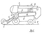
- a combine harvester 2 is shown with a chassis, a frame, a Cutting device 4 and inclined conveyor 6 for harvesting and transporting crops and one Threshing or insertion drum 8, a separating rotor 10 which rotates in a rotor housing 12 is drivably mounted, and a storage chute 14 for processing and dispensing the Crop.
- a motor 16 through which the self-propelled combine as well as his work organs are driven.
- the transfer zone can be seen from the front in the direction of the insertion drum. It is well recognizable that practically the entire width of the acceptance zone below the cutting line III-III can harvest harvested crop without immediate crop redirection.
- the side and below the separating rotors 10 arranged pockets are on the by dashes sketched edge lines of the transition zone recognizable. With an appropriate tool the surface of the transition zone could also be smoothly rounded. It is good recognizable that the rounded baffles in the transition zone from the outside widen the corner points towards the rear and inside towards the rotor housing opening
- a transfer zone is shown in a sectional view from above in FIG.
- the Threshing or inserting drum 8 undermines the crop in the effective range of Separating rotors 10, which are equipped with conveyor tools 18 in the form of screw plates.
- the separating rotor 10 has a tubular rotor core 20 which is located in its front part tapered. In this zone, the web height of the conveyor tools increases accordingly Cone angle so that an essentially cylindrical outer contour is maintained. It would also be conceivable that the outer contour is slightly forward expands or diminishes without being of concern to the claimed invention.
- the rotor housing 12 has side plates 22 in its front region, which in one horizontal position in the direction of crop flow - i.e. to the rear - seen converging to associated separating rotor 10 are arranged.
- 3 are both Side plates 22 of a rotor housing 12 shown converging, can according to the invention however, only one of the side plates 22 can be made converging.
- the degree of convergence and indirectly also the angle of convergence are essentially dependent on the Width of the threshing or insertion drum 8, the diameters of the separating rotors 10 and the Distance between the enveloping circle of the separating rotors 10 and the rotor housings 12 and that itself derived diameter of the rotor housing 12
- the angle of convergence is dependent of the degree of convergence and the depth of the acceptance zone 24. That of the side plates 22 realized convergence measure can be the difference between the width of the whole or in part Threshing or insertion drum 8 and the sum of the overall width of the two rotor housings 12 remove. The person skilled in the art is able to use these values to determine one for his application select appropriate design.
- FIG. 3 The sectional view of Figure 3 runs along the line III - III in Figure 2 and shows the Transfer zone approximately at the level of the axis of rotation of the separating rotors 10, with a lower one horizontal position of the section under consideration would result in the smaller rotor diameter correspondingly adapted geometries of the side plates 22. If the side plates 22 one
- the rotor housing is formed from a single piece of sheet metal Side panel of course only in a horizontal position to the side of the axis of rotation Separating rotor 10 arranged parts of the sheet metal piece, which then down in Transition zones and a bottom piece 23 merges.
- a side plate 22 and the opposite jacket of the conical rotor core 20 each have an acceptance zone 24.
- Zones 24 in FIG. 2 identified by hatching.
- This acceptance zone 24 will only about half captured by the conveyor tool 18.
- a comparable acceptance zone is also on 3 other places recognizable.
- a separating wedge 28 is flush with the two middle side plates 22, but is detachable upstream, the side flanks 29 the areas of the side plates 22 in some areas continue and merge into a wedge edge 31, which is the enveloping circle of threshers Insert drum 8 adapted and rises to about the level of the axes of rotation Separating rotors 10.
- Such an arrangement of the separating wedge 28 allows the threshing or Positioning drum 8 very close to the conveyor tools 18, which is a very space-saving arrangement and a good conveying effect results.
- the side plate 22 is roughly to be understood as the zone that between the dotted lines.
- the floor pan consists of the flat surface shown in a triangle 30, which can also be trapezoidal. It is important that the broad base is ahead and the triangle or trapezoid tapers towards the back and becomes narrower.
- the Side plates 22 and the flat surface 30 are interconnected by the transition surfaces 32 connected, which are bent up or folded sideways and in their area to the rear increasingly widen it. In this way, seams 34 form in their Towards the cross-section of the separator housing.
- One stretched in length Feed zone can be formed if the bottom plate is below the threshing or Insert drum extends and extends to the front edge of the rotor housing.
- FIG 5 it can be seen how the crop from the threshing or loading drum 8 on the side Separating rotor 10 demanded past in the receiving pockets and from there from the separating rotor 10 taken and converted into a radial conveying movement. This is preferably done on both sides of both separating rotors. Also the relative altitude of threshing or is good Insert drum 8 can be seen relative to the height of the separating rotors 10. In the shown Arrangement ensures that the crop preferably the crop in the area promotes between the axis of rotation of the separating rotors and the bottom plate in which the trained Bags are the easiest to swallow.
Landscapes
- Life Sciences & Earth Sciences (AREA)
- Environmental Sciences (AREA)
- Harvester Elements (AREA)
- Threshing Machine Elements (AREA)
- Guiding Agricultural Machines (AREA)
Claims (8)
- Moissonneuse-batteuse (2) automotrice comportant un train roulant, un châssis, des outils de travail pour ramasser, transporter, traiter et délivrer le produit récolté et des moyens d'entraínement pour entraíner les organes de travail, les organes de travail comprenant au moins un tambour de battage ou tambour d'alimentation (8) qui travaille selon le principe dit à flux tangentiel et deux rotors de séparation (10) placés derrière celui-ci, qui travaillent selon le principe dit à flux axial et sont montés entraínés en rotation dans des carters de rotor (12) enveloppants, des outils de transport (18) étant prévus sur les rotors de séparation, dans la région antérieure de ceux-ci vu dans la direction d'écoulement du produit, outils de transport qui, en rotation, engendrent un contour extérieur à forme de base essentiellement cylindrique des rotors de séparation portant lesdits outils de transport et la paroi extérieure des corps de rotor (20), dans la région antérieure, se rétrécissant en forme de cône dirigé vers l'avant,
caractérisée par le fait que
des tôles latérales (22) des carters de rotor (12) dans la région d'entrée antérieure, dans une position horizontale vu dans la direction d'écoulement du produit, sont disposées de manière convergente en direction du rotor de séparation (10) associé pour former une zone d'entrée qui se rétrécit en rapport avec le corps de rotor dans la direction de transport et dans laquelle seule une portion de zone d'entrée coopère de manière active sur le plan du transport avec les outils de transport (18). - Moissonneuse-batteuse automotrice selon la revendication 1,
caractérisée par le fait que sur la face intérieure d'une tôle latérale (22) le long de laquelle le rotor de séparation (10) associé se déplace avec un mouvement de rotation ascendant, est/sont montée(s) une ou plusieurs barrettes de guidage (26) qui sont orientées vers le haut suivant un angle aigu, présentent une extrémité amincie et dont la hauteur augmente progressivement dans la direction de transport. - Moissonneuse-batteuse automotrice selon la revendication 1 ou 2, caractérisée par le fait qu'aucune barrette de guidage (26) n'est prévue sur la face intérieure d'une tôle latérale (22) le long de laquelle le rotor de séparation (10) associé se déplace avec un mouvement de rotation descendant,
- Moissonneuse-batteuse automotrice selon une des revendications précédentes, caractérisée par le fait que devant les deux tôles latérales (22) médianes est disposé un bec-séparateur (28) longitudinal dont le profil est partiellement adapté au cercle enveloppe du tambour de battage ou d'alimentation (8) et qui s'étend depuis la région du fond jusqu'à environ la hauteur des axes de rotation des rotors de séparation (10).
- Moissonneuse-batteuse automotrice selon une ou plusieurs des revendications précédentes, caractérisée par le fait que la distance entre le cercle-enveloppe du tambour de battage ou d'alimentation (8) et les outils de transport (18) disposés sur le rotor de séparation (10) est au maximum égale à trois fois la hauteur maximale du bec-séparateur (28) par rapport aux surfaces des tôles de guidage voisines.
- Moissonneuse-batteuse automotrice selon une ou plusieurs des revendications précédentes, caractérisée par le fait que le tambour de battage ou d'alimentation (8) placé disposé en amont des rotors de séparation (10) occupe une position relative en hauteur devant les rotors de séparation (10) telle qu'il délivre le produit récolté sensiblement au milieu dans la région entre les axes de rotation des rotors de séparation (10) et les tôles d'entrée côté fond de la zone de transfert.
- Moissonneuse-batteuse automotrice selon une ou plusieurs des revendications précédentes, caractérisée par le fait qu'une tôle de fond qui relie les deux tôles latérales (22) d'un carter de rotor (12) est formée d'une surface plane de forme triangulaire ou trapézoïdale, dont la grande base est disposée côté avant et dont la largeur diminue jusque dans la région d'action des outils de transport (18) d'un rotor de séparation (10), sur le côté, des surfaces de transition qui sont liées à la surface plane par des cordons de soudure, étant courbées ou pliées vers le haut a des fins de raccordement au bord inférieur des tôles latérales et s'élargissant dans la direction de transport.
- Moissonneuse-batteuse automotrice selon la revendication 7,
caractérisée par le fait que la surface plane et les surfaces de transition latérales de la tôle de fond commencent en-dessous du tambour de battage ou d'alimentation (8) et s'étendent jusqu'au bord inférieur du carter de rotor (12) de forme rectangulaire.
Applications Claiming Priority (2)
| Application Number | Priority Date | Filing Date | Title |
|---|---|---|---|
| DE10019667 | 2000-04-19 | ||
| DE10019667A DE10019667A1 (de) | 2000-04-19 | 2000-04-19 | Selbstfahrender Mähdrescher |
Publications (2)
| Publication Number | Publication Date |
|---|---|
| EP1147701A1 EP1147701A1 (fr) | 2001-10-24 |
| EP1147701B1 true EP1147701B1 (fr) | 2004-07-28 |
Family
ID=7639499
Family Applications (1)
| Application Number | Title | Priority Date | Filing Date |
|---|---|---|---|
| EP01107220A Expired - Lifetime EP1147701B1 (fr) | 2000-04-19 | 2001-03-23 | Moissonneuse-batteuse automotrice |
Country Status (7)
| Country | Link |
|---|---|
| US (1) | US6517431B2 (fr) |
| EP (1) | EP1147701B1 (fr) |
| AT (1) | ATE271758T1 (fr) |
| BR (1) | BR0101491A (fr) |
| DE (2) | DE10019667A1 (fr) |
| RU (1) | RU2264702C2 (fr) |
| UA (1) | UA71927C2 (fr) |
Families Citing this family (26)
| Publication number | Priority date | Publication date | Assignee | Title |
|---|---|---|---|---|
| US20080058042A1 (en) * | 2006-05-25 | 2008-03-06 | Isaac Nathan E | Rigid rotor discharge deflector |
| US20080092507A1 (en) * | 2006-10-18 | 2008-04-24 | Dragotec Usa, Inc. | Corn head with tension control for deck plates |
| GB0710995D0 (en) * | 2007-06-08 | 2007-07-18 | Agco Do Brasil Com E Ind Stria | Combines |
| GB0710994D0 (en) * | 2007-06-08 | 2007-07-18 | Agco Do Brasil Com E Ind Stria | Combines |
| US20130025291A1 (en) | 2011-07-29 | 2013-01-31 | General Electric Company | System and method for protection of high temperature machinery components |
| DE102012105880B4 (de) * | 2012-07-03 | 2020-01-02 | Claas Selbstfahrende Erntemaschinen Gmbh | Mähdrescher |
| CN103609264B (zh) * | 2013-11-19 | 2015-08-19 | 山东省农业科学院农产品研究所 | 一种台式单穗小麦脱粒机 |
| DE102014109702A1 (de) | 2014-07-10 | 2016-01-14 | Claas Selbstfahrende Erntemaschinen Gmbh | Einlaufkopfgehäuse |
| DE102014114025A1 (de) * | 2014-09-26 | 2016-03-31 | Claas Selbstfahrende Erntemaschinen Gmbh | Mähdrescher mit einer tangential angeordneten Drescheinrichtung |
| JP6544938B2 (ja) * | 2015-02-13 | 2019-07-17 | 株式会社クボタ | 自脱型コンバイン |
| US9807937B2 (en) * | 2015-07-16 | 2017-11-07 | Cnh Industrial America Llc | Agricultural harvester with improved rotor transition geometry |
| US10159192B2 (en) * | 2015-09-17 | 2018-12-25 | Cone Guard, Llc | Transition cone liner for a farm combine |
| BR102016023877B1 (pt) * | 2015-10-16 | 2021-09-14 | Cnh Industrial America Llc | Colheitadeira agrícola |
| RU2631344C1 (ru) * | 2016-04-07 | 2017-09-21 | Федеральное государственное бюджетное образовательное учреждение высшего образования "Брянский государственный аграрный университет" | Зерноуборочный комбайн |
| US10653070B2 (en) * | 2017-03-03 | 2020-05-19 | Deere & Company | Dual auger baler |
| US10420285B2 (en) * | 2017-06-16 | 2019-09-24 | Cnh Industrial America Llc | Transition device for a combine threshing system |
| CN111867359B (zh) * | 2018-03-15 | 2022-10-04 | 凯斯纽荷兰(中国)管理有限公司 | 切向进料到脱粒转子 |
| US11116137B2 (en) * | 2018-04-12 | 2021-09-14 | Cnh Industrial America Llc | Concave ramp for an agricultural vehicle |
| US11234373B2 (en) * | 2019-08-13 | 2022-02-01 | Cnh Industrial America Llc | Crop flow guide vanes |
| US12369529B2 (en) * | 2021-12-30 | 2025-07-29 | Cnh Industrial America Llc | Variable cross-section vane for transition cone in combine harvester |
| DE102022103974A1 (de) * | 2022-02-21 | 2023-08-24 | Claas Selbstfahrende Erntemaschinen Gmbh | Selbstfahrender Mähdrescher |
| DE102022123328A1 (de) * | 2022-09-13 | 2024-03-14 | Claas Selbstfahrende Erntemaschinen Gmbh | Selbstfahrender Mähdrescher |
| DE102022123307A1 (de) * | 2022-09-13 | 2024-03-14 | Claas Selbstfahrende Erntemaschinen Gmbh | Dreschtrommel für eine Drescheinrichtung eines Mähdreschers sowie Mähdrescher |
| DE102022123311A1 (de) * | 2022-09-13 | 2024-03-14 | Claas Selbstfahrende Erntemaschinen Gmbh | Selbstfahrender Mähdrescher |
| US20240138317A1 (en) * | 2022-10-27 | 2024-05-02 | Deere & Company | Dual Rotor Deflector System and Method |
| US20240138318A1 (en) * | 2022-10-27 | 2024-05-02 | Deere & Company | Dual Rotor Crop Load System and Method |
Family Cites Families (20)
| Publication number | Priority date | Publication date | Assignee | Title |
|---|---|---|---|---|
| US3645270A (en) * | 1969-01-09 | 1972-02-29 | Sperry Rand Corp | Axial flow threshing and separating unit creating an airflow along the grain pan |
| BE788802A (nl) * | 1971-07-06 | 1973-01-02 | Clayson Nv | Verbeteringen aan maaidorsers. |
| US3827443A (en) * | 1973-06-29 | 1974-08-06 | Int Harvester Co | Conical transition |
| US3828794A (en) * | 1973-06-29 | 1974-08-13 | Int Harvester Co | Crop-diverting shed bar and bearing protector for axial flow-type combines |
| US3994303A (en) * | 1975-11-17 | 1976-11-30 | Sperry Rand Corporation | Axial flow combine having conical augers |
| US3994304A (en) * | 1976-01-06 | 1976-11-30 | Sperry Rand Corporation | Back-flow retarding feed plate for rotary combine |
| US4197693A (en) * | 1979-01-31 | 1980-04-15 | Sperry Rand Corporation | Feeder housing seal |
| US4291709A (en) * | 1980-07-02 | 1981-09-29 | Sperry Corporation | Infeed geometry |
| US4611605A (en) * | 1984-08-29 | 1986-09-16 | Deere & Company | Axial flow rotary separator |
| DE3535427C2 (de) * | 1985-10-04 | 1994-06-16 | Claas Ohg | Trenn- und Reinigungseinrichtung für einen selbstfahrenden Mähdrescher |
| US4739773A (en) * | 1986-05-09 | 1988-04-26 | Deere & Company | Feeding arrangement for an axial flow rotary separator |
| US4875890A (en) * | 1988-02-29 | 1989-10-24 | Ford New Holland, Inc. | Feed plate assembly for axial flow combine |
| SU1715238A1 (ru) * | 1988-06-24 | 1992-02-28 | Производственное объединение "Таганрогский комбайновый завод" | Молотильно-сепарирующее устройство |
| DE3932370A1 (de) * | 1989-09-28 | 1991-04-11 | Claas Ohg | Selbstfahrender maehdrescher |
| US4986794A (en) * | 1990-04-03 | 1991-01-22 | J. I. Case Company | Rotor assembly for an axial-flow combine |
| US5145462A (en) * | 1991-06-10 | 1992-09-08 | Case Corporation | Infeed assembly for an axial-flow combine |
| DE4232450A1 (de) | 1992-09-28 | 1994-03-31 | Claas Ohg | Selbstfahrender Mähdrescher |
| US5556337A (en) * | 1992-09-28 | 1996-09-17 | Claas Ohg Beschraebkt Haftende Offene | Self-propelling harvester thresher |
| DE19722079A1 (de) * | 1997-05-27 | 1998-12-03 | Claas Selbstfahr Erntemasch | Einzugsbereich eines Axialabscheiders |
| US6129629A (en) * | 1997-05-27 | 2000-10-10 | Claas Selbstfahrende Erntemaschinen Gmbh | Intake zone for axial separator |
-
2000
- 2000-04-19 DE DE10019667A patent/DE10019667A1/de not_active Withdrawn
-
2001
- 2001-03-23 DE DE50102955T patent/DE50102955D1/de not_active Expired - Lifetime
- 2001-03-23 AT AT01107220T patent/ATE271758T1/de not_active IP Right Cessation
- 2001-03-23 EP EP01107220A patent/EP1147701B1/fr not_active Expired - Lifetime
- 2001-04-16 RU RU2001109972/12A patent/RU2264702C2/ru not_active IP Right Cessation
- 2001-04-17 BR BR0101491-9A patent/BR0101491A/pt active Search and Examination
- 2001-04-18 UA UA2001042638A patent/UA71927C2/uk unknown
- 2001-04-19 US US09/838,771 patent/US6517431B2/en not_active Expired - Lifetime
Also Published As
| Publication number | Publication date |
|---|---|
| UA71927C2 (en) | 2005-01-17 |
| ATE271758T1 (de) | 2004-08-15 |
| RU2264702C2 (ru) | 2005-11-27 |
| US6517431B2 (en) | 2003-02-11 |
| US20010054279A1 (en) | 2001-12-27 |
| EP1147701A1 (fr) | 2001-10-24 |
| DE50102955D1 (de) | 2004-09-02 |
| BR0101491A (pt) | 2001-11-13 |
| DE10019667A1 (de) | 2002-01-03 |
Similar Documents
| Publication | Publication Date | Title |
|---|---|---|
| EP1147701B1 (fr) | Moissonneuse-batteuse automotrice | |
| DE2729033C2 (fr) | ||
| EP1106048B1 (fr) | Dispositif d'introduction et de cueillage d'un dispositif de chargement de récoltes | |
| DE69803321T2 (de) | Teiler des Fördertrogs der Einzugsschnecke von Maispflückvorsatz | |
| DE19959282A1 (de) | Einzugs- und Pflückeinrichtung mit Häckseleinrichtung | |
| EP0521280B1 (fr) | Séparateur axial | |
| DE19734747A1 (de) | Maisernte-Vorsatz zum Anbau an eine selbstfahrende Erntemaschine | |
| EP1106047A1 (fr) | Dispositif d'introduction et de cueillage et machine de récolte | |
| DE2729012A1 (de) | Maehdrescher | |
| DE2725588A1 (de) | Maehdrescher der axialflussbauart | |
| DE2736005A1 (de) | Reihenvorsatzgeraet fuer feldhaecksler | |
| DE3033229C2 (de) | Erntevorrichtung für vorzugsweise in Reihen angepflanztes stengelförmiges Erntegut mit vier Förderbahnen und einer Leitvorrichtung | |
| EP1428423B1 (fr) | Dispositif de prise et de cueillette | |
| DE10351858B4 (de) | Maschine zum Mähen von stängelartigem Erntegut | |
| EP1147702B1 (fr) | Moissonneuse-batteuse automotrice | |
| EP2232976A1 (fr) | Agencement de hachage et de répartition de résidus de produits de récolte pour une moissonneuse-batteuse | |
| DE2907271C2 (de) | Mähdrescher in Axialflußbauart | |
| DE10314081B4 (de) | Austrageinrichtung zum Austragen von Erntegut aus einer Erntemaschine | |
| EP3984347B1 (fr) | Mécanisme de coupe pourvu de dispositifs latéraux d'aide au transport | |
| DE3414576C2 (fr) | ||
| DE3239552C2 (fr) | ||
| EP1354508B1 (fr) | Separateur axial avec rail de guidage | |
| DE1164735B (de) | Schneckenfoerderer in Maehdreschern | |
| DE10026495A1 (de) | Erntegerät | |
| DE10360299A1 (de) | Maschine zum Mähen von stängelartigem Erntegut |
Legal Events
| Date | Code | Title | Description |
|---|---|---|---|
| PUAI | Public reference made under article 153(3) epc to a published international application that has entered the european phase |
Free format text: ORIGINAL CODE: 0009012 |
|
| AK | Designated contracting states |
Kind code of ref document: A1 Designated state(s): AT BE CH CY DE DK ES FI FR GB GR IE IT LI LU MC NL PT SE TR |
|
| AX | Request for extension of the european patent |
Free format text: AL;LT;LV;MK;RO;SI |
|
| 17P | Request for examination filed |
Effective date: 20020424 |
|
| AKX | Designation fees paid |
Free format text: AT BE CH CY DE DK ES FI FR GB GR IE IT LI LU MC NL PT SE TR |
|
| GRAP | Despatch of communication of intention to grant a patent |
Free format text: ORIGINAL CODE: EPIDOSNIGR1 |
|
| GRAS | Grant fee paid |
Free format text: ORIGINAL CODE: EPIDOSNIGR3 |
|
| GRAA | (expected) grant |
Free format text: ORIGINAL CODE: 0009210 |
|
| AK | Designated contracting states |
Kind code of ref document: B1 Designated state(s): AT BE CH CY DE DK ES FI FR GB GR IE IT LI LU MC NL PT SE TR |
|
| PG25 | Lapsed in a contracting state [announced via postgrant information from national office to epo] |
Ref country code: IT Free format text: LAPSE BECAUSE OF FAILURE TO SUBMIT A TRANSLATION OF THE DESCRIPTION OR TO PAY THE FEE WITHIN THE PRESCRIBED TIME-LIMIT;WARNING: LAPSES OF ITALIAN PATENTS WITH EFFECTIVE DATE BEFORE 2007 MAY HAVE OCCURRED AT ANY TIME BEFORE 2007. THE CORRECT EFFECTIVE DATE MAY BE DIFFERENT FROM THE ONE RECORDED. Effective date: 20040728 Ref country code: NL Free format text: LAPSE BECAUSE OF FAILURE TO SUBMIT A TRANSLATION OF THE DESCRIPTION OR TO PAY THE FEE WITHIN THE PRESCRIBED TIME-LIMIT Effective date: 20040728 Ref country code: GB Free format text: LAPSE BECAUSE OF FAILURE TO SUBMIT A TRANSLATION OF THE DESCRIPTION OR TO PAY THE FEE WITHIN THE PRESCRIBED TIME-LIMIT Effective date: 20040728 Ref country code: IE Free format text: LAPSE BECAUSE OF FAILURE TO SUBMIT A TRANSLATION OF THE DESCRIPTION OR TO PAY THE FEE WITHIN THE PRESCRIBED TIME-LIMIT Effective date: 20040728 Ref country code: TR Free format text: LAPSE BECAUSE OF FAILURE TO SUBMIT A TRANSLATION OF THE DESCRIPTION OR TO PAY THE FEE WITHIN THE PRESCRIBED TIME-LIMIT Effective date: 20040728 Ref country code: FI Free format text: LAPSE BECAUSE OF FAILURE TO SUBMIT A TRANSLATION OF THE DESCRIPTION OR TO PAY THE FEE WITHIN THE PRESCRIBED TIME-LIMIT Effective date: 20040728 |
|
| REG | Reference to a national code |
Ref country code: GB Ref legal event code: FG4D Free format text: NOT ENGLISH |
|
| REG | Reference to a national code |
Ref country code: CH Ref legal event code: EP |
|
| REG | Reference to a national code |
Ref country code: IE Ref legal event code: FG4D Free format text: GERMAN |
|
| REF | Corresponds to: |
Ref document number: 50102955 Country of ref document: DE Date of ref document: 20040902 Kind code of ref document: P |
|
| PG25 | Lapsed in a contracting state [announced via postgrant information from national office to epo] |
Ref country code: SE Free format text: LAPSE BECAUSE OF FAILURE TO SUBMIT A TRANSLATION OF THE DESCRIPTION OR TO PAY THE FEE WITHIN THE PRESCRIBED TIME-LIMIT Effective date: 20041028 Ref country code: DK Free format text: LAPSE BECAUSE OF FAILURE TO SUBMIT A TRANSLATION OF THE DESCRIPTION OR TO PAY THE FEE WITHIN THE PRESCRIBED TIME-LIMIT Effective date: 20041028 Ref country code: GR Free format text: LAPSE BECAUSE OF FAILURE TO SUBMIT A TRANSLATION OF THE DESCRIPTION OR TO PAY THE FEE WITHIN THE PRESCRIBED TIME-LIMIT Effective date: 20041028 |
|
| PG25 | Lapsed in a contracting state [announced via postgrant information from national office to epo] |
Ref country code: ES Free format text: LAPSE BECAUSE OF FAILURE TO SUBMIT A TRANSLATION OF THE DESCRIPTION OR TO PAY THE FEE WITHIN THE PRESCRIBED TIME-LIMIT Effective date: 20041108 |
|
| NLV1 | Nl: lapsed or annulled due to failure to fulfill the requirements of art. 29p and 29m of the patents act | ||
| GBV | Gb: ep patent (uk) treated as always having been void in accordance with gb section 77(7)/1977 [no translation filed] |
Effective date: 20040728 |
|
| ET | Fr: translation filed | ||
| PG25 | Lapsed in a contracting state [announced via postgrant information from national office to epo] |
Ref country code: CY Free format text: LAPSE BECAUSE OF FAILURE TO SUBMIT A TRANSLATION OF THE DESCRIPTION OR TO PAY THE FEE WITHIN THE PRESCRIBED TIME-LIMIT Effective date: 20050323 Ref country code: AT Free format text: LAPSE BECAUSE OF NON-PAYMENT OF DUE FEES Effective date: 20050323 Ref country code: LU Free format text: LAPSE BECAUSE OF NON-PAYMENT OF DUE FEES Effective date: 20050323 |
|
| REG | Reference to a national code |
Ref country code: IE Ref legal event code: FD4D |
|
| PG25 | Lapsed in a contracting state [announced via postgrant information from national office to epo] |
Ref country code: CH Free format text: LAPSE BECAUSE OF NON-PAYMENT OF DUE FEES Effective date: 20050331 Ref country code: LI Free format text: LAPSE BECAUSE OF NON-PAYMENT OF DUE FEES Effective date: 20050331 Ref country code: MC Free format text: LAPSE BECAUSE OF NON-PAYMENT OF DUE FEES Effective date: 20050331 |
|
| PLBE | No opposition filed within time limit |
Free format text: ORIGINAL CODE: 0009261 |
|
| STAA | Information on the status of an ep patent application or granted ep patent |
Free format text: STATUS: NO OPPOSITION FILED WITHIN TIME LIMIT |
|
| 26N | No opposition filed |
Effective date: 20050429 |
|
| REG | Reference to a national code |
Ref country code: CH Ref legal event code: PL |
|
| PG25 | Lapsed in a contracting state [announced via postgrant information from national office to epo] |
Ref country code: PT Free format text: LAPSE BECAUSE OF NON-PAYMENT OF DUE FEES Effective date: 20041228 |
|
| REG | Reference to a national code |
Ref country code: FR Ref legal event code: PLFP Year of fee payment: 15 |
|
| PGFP | Annual fee paid to national office [announced via postgrant information from national office to epo] |
Ref country code: FR Payment date: 20150319 Year of fee payment: 15 |
|
| REG | Reference to a national code |
Ref country code: FR Ref legal event code: ST Effective date: 20161130 |
|
| REG | Reference to a national code |
Ref country code: DE Ref legal event code: R084 Ref document number: 50102955 Country of ref document: DE |
|
| PG25 | Lapsed in a contracting state [announced via postgrant information from national office to epo] |
Ref country code: FR Free format text: LAPSE BECAUSE OF NON-PAYMENT OF DUE FEES Effective date: 20160331 |
|
| PGFP | Annual fee paid to national office [announced via postgrant information from national office to epo] |
Ref country code: DE Payment date: 20190129 Year of fee payment: 19 |
|
| PGFP | Annual fee paid to national office [announced via postgrant information from national office to epo] |
Ref country code: BE Payment date: 20190320 Year of fee payment: 19 |
|
| REG | Reference to a national code |
Ref country code: DE Ref legal event code: R119 Ref document number: 50102955 Country of ref document: DE |
|
| REG | Reference to a national code |
Ref country code: BE Ref legal event code: MM Effective date: 20200331 |
|
| PG25 | Lapsed in a contracting state [announced via postgrant information from national office to epo] |
Ref country code: DE Free format text: LAPSE BECAUSE OF NON-PAYMENT OF DUE FEES Effective date: 20201001 |
|
| PG25 | Lapsed in a contracting state [announced via postgrant information from national office to epo] |
Ref country code: BE Free format text: LAPSE BECAUSE OF NON-PAYMENT OF DUE FEES Effective date: 20200331 |