EP1147864B1 - Dispositif de coupe à grande vitesse pour couper un renfort de pneumatique - Google Patents
Dispositif de coupe à grande vitesse pour couper un renfort de pneumatique Download PDFInfo
- Publication number
- EP1147864B1 EP1147864B1 EP01108701A EP01108701A EP1147864B1 EP 1147864 B1 EP1147864 B1 EP 1147864B1 EP 01108701 A EP01108701 A EP 01108701A EP 01108701 A EP01108701 A EP 01108701A EP 1147864 B1 EP1147864 B1 EP 1147864B1
- Authority
- EP
- European Patent Office
- Prior art keywords
- reinforcing element
- support
- wire
- knife
- point
- Prior art date
- Legal status (The legal status is an assumption and is not a legal conclusion. Google has not performed a legal analysis and makes no representation as to the accuracy of the status listed.)
- Expired - Lifetime
Links
Images



Classifications
-
- B—PERFORMING OPERATIONS; TRANSPORTING
- B26—HAND CUTTING TOOLS; CUTTING; SEVERING
- B26D—CUTTING; DETAILS COMMON TO MACHINES FOR PERFORATING, PUNCHING, CUTTING-OUT, STAMPING-OUT OR SEVERING
- B26D1/00—Cutting through work characterised by the nature or movement of the cutting member or particular materials not otherwise provided for; Apparatus or machines therefor; Cutting members therefor
- B26D1/01—Cutting through work characterised by the nature or movement of the cutting member or particular materials not otherwise provided for; Apparatus or machines therefor; Cutting members therefor involving a cutting member which does not travel with the work
- B26D1/12—Cutting through work characterised by the nature or movement of the cutting member or particular materials not otherwise provided for; Apparatus or machines therefor; Cutting members therefor involving a cutting member which does not travel with the work having a cutting member moving about an axis
- B26D1/25—Cutting through work characterised by the nature or movement of the cutting member or particular materials not otherwise provided for; Apparatus or machines therefor; Cutting members therefor involving a cutting member which does not travel with the work having a cutting member moving about an axis with a non-circular cutting member
- B26D1/26—Cutting through work characterised by the nature or movement of the cutting member or particular materials not otherwise provided for; Apparatus or machines therefor; Cutting members therefor involving a cutting member which does not travel with the work having a cutting member moving about an axis with a non-circular cutting member moving about an axis substantially perpendicular to the line of cut
- B26D1/28—Cutting through work characterised by the nature or movement of the cutting member or particular materials not otherwise provided for; Apparatus or machines therefor; Cutting members therefor involving a cutting member which does not travel with the work having a cutting member moving about an axis with a non-circular cutting member moving about an axis substantially perpendicular to the line of cut and rotating continuously in one direction during cutting
-
- B—PERFORMING OPERATIONS; TRANSPORTING
- B21—MECHANICAL METAL-WORKING WITHOUT ESSENTIALLY REMOVING MATERIAL; PUNCHING METAL
- B21F—WORKING OR PROCESSING OF METAL WIRE
- B21F11/00—Cutting wire
-
- B—PERFORMING OPERATIONS; TRANSPORTING
- B29—WORKING OF PLASTICS; WORKING OF SUBSTANCES IN A PLASTIC STATE IN GENERAL
- B29D—PRODUCING PARTICULAR ARTICLES FROM PLASTICS OR FROM SUBSTANCES IN A PLASTIC STATE
- B29D30/00—Producing pneumatic or solid tyres or parts thereof
- B29D30/06—Pneumatic tyres or parts thereof (e.g. produced by casting, moulding, compression moulding, injection moulding, centrifugal casting)
- B29D30/38—Textile inserts, e.g. cord or canvas layers, for tyres; Treatment of inserts prior to building the tyre
- B29D30/46—Cutting textile inserts to required shape
-
- B—PERFORMING OPERATIONS; TRANSPORTING
- B29—WORKING OF PLASTICS; WORKING OF SUBSTANCES IN A PLASTIC STATE IN GENERAL
- B29D—PRODUCING PARTICULAR ARTICLES FROM PLASTICS OR FROM SUBSTANCES IN A PLASTIC STATE
- B29D30/00—Producing pneumatic or solid tyres or parts thereof
- B29D30/06—Pneumatic tyres or parts thereof (e.g. produced by casting, moulding, compression moulding, injection moulding, centrifugal casting)
- B29D30/08—Building tyres
- B29D30/10—Building tyres on round cores, i.e. the shape of the core is approximately identical with the shape of the completed tyre
- B29D30/16—Applying the layers; Guiding or stretching the layers during application
- B29D2030/1664—Details, accessories or auxiliary operations not provided for in the other subgroups of B29D30/00
- B29D2030/1685—Details, accessories or auxiliary operations not provided for in the other subgroups of B29D30/00 the layers being applied being already cut to the appropriate length, before the application step
-
- B—PERFORMING OPERATIONS; TRANSPORTING
- B29—WORKING OF PLASTICS; WORKING OF SUBSTANCES IN A PLASTIC STATE IN GENERAL
- B29D—PRODUCING PARTICULAR ARTICLES FROM PLASTICS OR FROM SUBSTANCES IN A PLASTIC STATE
- B29D30/00—Producing pneumatic or solid tyres or parts thereof
- B29D30/06—Pneumatic tyres or parts thereof (e.g. produced by casting, moulding, compression moulding, injection moulding, centrifugal casting)
- B29D30/08—Building tyres
- B29D30/20—Building tyres by the flat-tyre method, i.e. building on cylindrical drums
- B29D30/30—Applying the layers; Guiding or stretching the layers during application
- B29D2030/3064—Details, accessories and auxiliary operations not otherwise provided for
- B29D2030/3085—Details, accessories and auxiliary operations not otherwise provided for the layers being applied being already cut to the appropriate length, before the application step
-
- Y—GENERAL TAGGING OF NEW TECHNOLOGICAL DEVELOPMENTS; GENERAL TAGGING OF CROSS-SECTIONAL TECHNOLOGIES SPANNING OVER SEVERAL SECTIONS OF THE IPC; TECHNICAL SUBJECTS COVERED BY FORMER USPC CROSS-REFERENCE ART COLLECTIONS [XRACs] AND DIGESTS
- Y10—TECHNICAL SUBJECTS COVERED BY FORMER USPC
- Y10T—TECHNICAL SUBJECTS COVERED BY FORMER US CLASSIFICATION
- Y10T156/00—Adhesive bonding and miscellaneous chemical manufacture
- Y10T156/12—Surface bonding means and/or assembly means with cutting, punching, piercing, severing or tearing
- Y10T156/1317—Means feeding plural workpieces to be joined
Definitions
- the present invention relates to the manufacture of tires. More precisely, it is relates to the manufacture of reinforcing reinforcements, especially for the top of the pneumatic.
- thread refers indiscriminately to a single strand as a monofilament, or an assembly of single strands as a cable
- reinforcement also refers to indistinctly a single thread, or a group of parallel threads.
- the threads can be bare or pre coated with rubber or any other material suitable for making the threads sticky.
- US Pat. No. 5,281,289 discloses a method manufacturing a tire, including a reinforcement is made from a single wire of which successive sections are placed on a support rigid.
- This patent also describes a machine for implementation of this method.
- the aim of the invention is to propose very fast cutting means, that these cuts frequent, as in the case described above, or that cutting only occurs at the end of the tire operation, as in the case of reinforcements at zero degrees in continuous wire.
- the invention makes it possible to envisage in good performance conditions industrial laying of wire stretches for any strengthening application.
- Cutting on demand can be done by a suitable actuator.
- the construction of the control is such that the knife is active at the cutting point every n passages, n greater than or equal to two.
- the invention proposes to rotate a knife at very high speed and, by a kinematic appropriate, to ensure that the knife is not active at each pass near the reinforcement.
- the invention exploits the arrangement known per se of satellite gears existing in some gearboxes. This makes it possible to have the knife described a trajectory included in a plane.
- the invention allows a direct manufacture on a support, from coils in which the reinforcement is taken continuously.
- the medium in question can be a form of revolution on which a top block is made, or a drum that supports the raw tire during manufacture, or any other suitable medium, the invention does not in itself deal with this aspect.
- the support is coated with a layer of raw rubber to which the reinforcement can adhere, or in which the reinforcement can penetrate at least slightly as and that he is brought to the support.
- FIG 1 there is a support 1 on which a reinforcement is manufactured.
- This support could be constituted by any type of shape defining the surface on which we will dispose the sections of wire constituting the reinforcement, such as for example an armed membrane inflatable, or a shape adjustable in diameter of the kind used in machines of crown block construction imposing a purely cylindrical profile, or a curved shape transversely.
- the support 1 is already coated with all the constituents that it must receive before the addition of reinforcement to zero degrees.
- the support 1 is rotated in the direction indicated by the arrow A.
- the wire 3 is unwound from a coil (not shown). Wire 3 is engaged on different pulleys from a compass system 32 allowing it, from a fixed point in the space (pulley 33), to join a laying head 34 mobile in space.
- a robot 35 to three axes (Y, Z, ⁇ ) makes it possible to ensure the correct presentation of the wire 3 at any point on the surface of the support 1, even when the support is of non-cylindrical shape.
- the wire 3 On the laying head, the wire 3 is motorized by two rollers 20, 21 between which it is pinched. The roller 20 is driven by a motor (not shown) in advance of the wire 3.
- the advance engine may comprise an encoder or a resolver. It is thus possible to impose on wire 3 a precise linear advance while knowing in continuous accurate measurement of the amount of wire 3 delivered to the organs of the machine arranged downstream.
- the wire 3 is introduced into a cutting device 4, installed on the 34.
- the cutting device is, in this example, adapted to a reinforcement consisting of a single wire.
- an applique roller 5 presses the wire 3 against the support 1 to make it penetrate slightly into the rubber of which is coated the support 1.
- the wall roller 5 is shown fixed to the drawing seal, although it can be mounted on an elastic suspension in the radial direction by report to the support.
- a tubular guide 40 is seen whose reinforced end 41 determines the position of the cutting point and holds the wire 3 when sliced.
- a knife 42 is mounted on a disk 43 integral with a planet gear 44 (the disk 43 and the planet gear 44 being rotatably mounted on the same shaft 45).
- the planet gear 44 is engaged with a wheel toothed 46 fixed mount, ie non-rotating (it could be indifferently a ring gear internally or externally, or any other suitable arrangement).
- the shaft 45 is mounted on a planet carrier 47 driven in rotation by a cutting motor 48.
- the device 4 may comprise one or more other non-active auxiliary discs such as the auxiliary disk 49, with corresponding pinion (s) satellite (s), in particular for balancing issues.
- the knife 42 can describe several turns, according to the gear reduction due to the ratio between the number of teeth of the planet gear 44 and the wheel 46. It should also be noted that, according to the report chosen, the knife will not be cutting point in front of the end 41 that after a number of towers of the carrier 47.
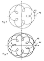
- FIG. 3 illustrates the trajectory of the knife 42 in the case where it returns to the point cutting every two turns of the planet carrier 47 and figure 4 illustrates the trajectory of the knife 42 in the case where it returns to the point of cut every three turns of the planet carrier 47.
- the section 30 of wire no longer benefits from the motorization by the rollers 20 and 21 installed upstream. For this reason, the difference between the cutting point and the laying point so that the last end of the thread 3 created by the previous cut join the laying point on the support 1 just before the wire 3 is again cut.
- the movement of the section 30 is caused by the rotation of the support 1 on which he adheres.
- the distance between the point of contact of the applied roller on the support and the cutting point corresponding at most to the length of the sections. Note that if the kinetic energy accumulated by the sections is sufficient, it is possible to ensure the operation of the described machine even if the distance between the point of contact of the roller of applied on the support and the point of cut is higher than the maximum mentioned above.
- FIGS. 5 and 6 show a cutting device 14 constituting another embodiment of embodiment that can replace the cutting device 4 of Figure 1.
- the cutting device 14 is mounted on a laying head 134. It comprises a guide comparable to the guide 40, along said reinforcement is introduced, the end 141 of said guide defining a cutting point of the reinforcement.
- a knife 142 mounted on a rotating disc 143, driven in rotation by a pinion 145 (via a belt), the pinion 145 being integral in rotation with a cam 146.
- a bar 147 supports the axis 144 of the disk 143 and the axis 148 of the assembly formed by the cam 146 and the pinion 145.
- the bar 147 is guided by rollers 137 mounted on the laying head 134.
- the cam 146 and the disc 143 are thus slidably mounted with respect to the laying head 134.
- the cam comprises a boss 149, and it cooperates with a pin 136 integral with the head 134.
- the knife 142 is permanently driven at high speed. He is in position inactive in Figure 6 and, when desired, advance to the wire 3 to cut (see Figure 5).
- the cutting device 14 is thus arranged so that the knife 142 describes a trajectory that crosses the reinforcement at said cutting point when the boss 149 of the cam is engaged on the pawn (136).
Landscapes
- Engineering & Computer Science (AREA)
- Mechanical Engineering (AREA)
- Life Sciences & Earth Sciences (AREA)
- Forests & Forestry (AREA)
- Textile Engineering (AREA)
- Tyre Moulding (AREA)
- Knives (AREA)
- Crushing And Pulverization Processes (AREA)
Description
- faire coulisser ledit renfort dans un guide dont un orifice définit un point de coupe,
- entraíner au moyen d'une commande par arbre rotatif un couteau selon une trajectoire fermée quelconque amenant le couteau à passer dans l'environnement du point de coupe, le couteau étant actif au point de coupe tous les n passages, avec n supérieur ou égal à deux.
- un guide guidant ledit renfort, l'orifice aval dudit guide définissant un point de coupe du renfort,
- un couteau monté sur un disque rotatif
Claims (8)
- Procédé de fabrication d'un renforcement pour pneumatique, ledit renforcement étant constitué à partir d'un renfort délivré par des moyens d'alimentation imposant au renfort un mouvement d'avance à une vitesse linéaire donnée dans la direction longitudinale du renfort, consistant à déposer des tronçons dudit renfort sur un support, à retenir lesdits tronçons sur le support par adhérence sur celui-ci, lesdits tronçons étant prélevés en aval des moyens d'alimentation de la façon suivante :faire coulisser ledit renfort dans un guide dont un orifice définit un point de coupe,entraíner au moyen d'une commande par arbre rotatif un couteau selon une trajectoire fermée quelconque amenant le couteau à passer dans l'environnement du point de coupe, le couteau étant actif au point de coupe tous les n passages, avec n supérieur ou égal à deux.
- Procédé selon la revendication 1, dans lequel la trajectoire est comprise dans un plan.
- Procédé selon la revendication 1, dans lequel le renfort est appliqué sur le support par un galet d'applique en appui sur le support, ledit galet étant entraíné en rotation par le mouvement du support, la distance entre le point de contact du galet d'applique sur le support et le point de coupe correspondant au maximum à la longueur des tronçons.
- Machine de fabrication d'un renforcement pour pneumatique, comportant un distributeur de renfort imposant à un renfort un mouvement d'avance à une vitesse linéaire donnée dans la direction longitudinale du renfort, et un dispositif de coupe (4 ou 14) comportant :caractérisé en ce que le disque est commandé par une cinématique appropriée pour faire tourner ledit couteau à très haute vitesse et appropriée pour faire en sorte que le couteau ne soit pas actif à chaque passage près du renfort, ledit dispositif de coupe étant agencé de façon à ce que le couteau décrive une trajectoire qui croise le renfort audit point de coupe et en ce que la machine comporte des moyens d'application recevant le renfort en aval du point de coupe, l'acheminant jusqu'à un point de pose du renfort sur un support de fabrication du renforcement.un guide guidant ledit renfort, l'extrémité (41 ou 141) aval dudit guide définissant un point de coupe du renfort,un couteau (42 ou 142) monté sur un disque rotatif (43 ou 143)
- Machine selon la revendication 4, dans laquelle la cinématique appropriée est réalisée par le montage dudit disque rotatif (43) autour d'un arbre entraíné en rotation par un pignon satellite (44) en prise sur une roue dentée fixe (46), le pignon satellite (44) étant entraíné par un porte satellite (47) de façon à ce que le pignon satellite roule sur la roue dentée fixe.
- Machine selon la revendication 4, dans laquelle le dispositif de coupe (14) est monté sur une tête de pose (134) et dans laquelle la cinématique appropriée est réalisée par le fait que ledit disque rotatif (143) est entraíné en rotation par un pignon (145), le pignon (145) étant solidaire en rotation d'une came (146), la came et le disque étant montés coulissant par rapport à la tête de pose (134), la came comportant un bossage (149) et coopérant avec un pion (136) solidaire de la tête de pose (134), ledit dispositif de coupe étant agencé de façon à ce que le couteau décrive une trajectoire qui croise le renfort audit point de coupe lorsque le bossage (149) de la came est engagé sur le pion (136).
- Machine selon l'une des revendications 4 à 6, dans laquelle les moyens d'application comprennent un galet d'applique (5) disposé de façon à agir sur le renfort au point de pose.
- Machine selon l'une des revendications 4 à 7 dans laquelle le guide est tubulaire.
Applications Claiming Priority (2)
| Application Number | Priority Date | Filing Date | Title |
|---|---|---|---|
| FR0005071 | 2000-04-18 | ||
| FR0005071 | 2000-04-18 |
Publications (3)
| Publication Number | Publication Date |
|---|---|
| EP1147864A2 EP1147864A2 (fr) | 2001-10-24 |
| EP1147864A3 EP1147864A3 (fr) | 2003-05-07 |
| EP1147864B1 true EP1147864B1 (fr) | 2005-07-06 |
Family
ID=8849438
Family Applications (1)
| Application Number | Title | Priority Date | Filing Date |
|---|---|---|---|
| EP01108701A Expired - Lifetime EP1147864B1 (fr) | 2000-04-18 | 2001-04-06 | Dispositif de coupe à grande vitesse pour couper un renfort de pneumatique |
Country Status (5)
| Country | Link |
|---|---|
| US (1) | US6969438B2 (fr) |
| EP (1) | EP1147864B1 (fr) |
| JP (1) | JP4755356B2 (fr) |
| AT (1) | ATE299079T1 (fr) |
| DE (1) | DE60111798T2 (fr) |
Families Citing this family (15)
| Publication number | Priority date | Publication date | Assignee | Title |
|---|---|---|---|---|
| RU2264274C2 (ru) * | 2004-01-08 | 2005-11-20 | Открытое акционерное общество "Ульяновский механический завод" | Устройство для мерной резки проволоки с формовкой торца |
| DE602005008708D1 (de) * | 2004-01-27 | 2008-09-18 | Michelin Soc Tech | Verfahren und vorrichtung zur herstellung einer reifenverstärkung |
| FR2879500A1 (fr) * | 2004-12-22 | 2006-06-23 | Michelin Soc Tech | Procede et dispositif pour la fabrication et la pose d'un renforcement circonferentiel pour pneumatique et pneumatique obtenu par ledit procede |
| US7740039B2 (en) * | 2005-12-01 | 2010-06-22 | The Goodyear Tire & Rubber Company | Cord cutting mechanism and method for a tire cord applicator head |
| FR2908072A1 (fr) * | 2006-11-02 | 2008-05-09 | Michelin Soc Tech | Dispositif et procede de guidage d'un fil |
| CN100423867C (zh) * | 2006-11-17 | 2008-10-08 | 宁波长城精工实业有限公司 | 一种卷尺切零机 |
| US20080314524A1 (en) * | 2007-06-20 | 2008-12-25 | Andres Ignacio Delgado | Method for single line tire ply construction |
| US20080314216A1 (en) * | 2007-06-20 | 2008-12-25 | Andres Ignacio Delgado | Tire cord cutting apparatus |
| EP2006078B1 (fr) * | 2007-06-20 | 2011-05-25 | The Goodyear Tire & Rubber Company | Appareil de découpe de corde pour pneu et procédé de construction de pli de pneu à ligne unique |
| JP2009061717A (ja) * | 2007-09-07 | 2009-03-26 | Bridgestone Corp | タイヤ補強帯の製造装置およびタイヤ補強帯の製造方法 |
| CN102688959A (zh) * | 2012-06-19 | 2012-09-26 | 曲海涛 | 简易钢筋调直切断机 |
| US10307980B2 (en) * | 2013-02-20 | 2019-06-04 | The Goodyear Tire & Rubber Company | Tire building applicator members and systems |
| US20150041067A1 (en) * | 2013-08-07 | 2015-02-12 | The Goodyear Tire & Rubber Company | Component applying/cutting apparatus for a tire building machine |
| CN104475553B (zh) * | 2014-11-26 | 2016-07-27 | 揭阳榕申卷尺有限公司 | 一种返卷弹簧全自动成型机 |
| CN110238322A (zh) * | 2019-05-17 | 2019-09-17 | 安徽明洋电子有限公司 | 一种散装双排数码管剪脚装置及其使用方法 |
Family Cites Families (10)
| Publication number | Priority date | Publication date | Assignee | Title |
|---|---|---|---|---|
| US3894906A (en) * | 1973-06-01 | 1975-07-15 | Nat Standard Co | Apparatus for making tire breakers |
| US4640164A (en) * | 1985-05-02 | 1987-02-03 | Essex Group, Inc. | High speed wire cutter |
| GB8708977D0 (en) * | 1987-04-14 | 1987-05-20 | Goodyear Tire & Rubber | Reinforcing plies for tyres |
| IT1213652B (it) * | 1987-07-22 | 1989-12-29 | Gd Spa | Dispositivo per il taglio trasversale in spezzoni di un nastro mobile di moto continuo lungo un percorso determinato |
| US4941378A (en) * | 1988-10-24 | 1990-07-17 | General Motors Corporation | Method and apparatus for rapid repetitive cutting |
| FR2677578A1 (fr) * | 1991-06-17 | 1992-12-18 | Sedepro | Procede de fabrication d'un pneumatique et machines pour la mise en óoeuvre de ce procede. |
| FR2694519A1 (fr) * | 1992-08-07 | 1994-02-11 | Sedepro | Procédé de fabrication d'un pneumatique et machine de fabrication d'un renfort de sommet pour pneumatique. |
| DE59502561D1 (de) * | 1994-05-25 | 1998-07-23 | Ferag Ag | Schneidvorrichtung mit einem scheibenförmigen Schneidelement |
| DE19520161C1 (de) * | 1995-06-01 | 1996-10-17 | Bellaform Extrusionstech Gmbh | Vorrichtung zum Ablängen oder Schlitzen von kontinuierlich bewegtem, strangförmigem Material |
| US6032560A (en) * | 1997-10-24 | 2000-03-07 | Morgan Construction Company | High speed trimming shear |
-
2001
- 2001-04-06 EP EP01108701A patent/EP1147864B1/fr not_active Expired - Lifetime
- 2001-04-06 DE DE60111798T patent/DE60111798T2/de not_active Expired - Lifetime
- 2001-04-06 AT AT01108701T patent/ATE299079T1/de not_active IP Right Cessation
- 2001-04-18 US US09/837,523 patent/US6969438B2/en not_active Expired - Fee Related
- 2001-04-18 JP JP2001120197A patent/JP4755356B2/ja not_active Expired - Fee Related
Also Published As
| Publication number | Publication date |
|---|---|
| US20020003020A1 (en) | 2002-01-10 |
| ATE299079T1 (de) | 2005-07-15 |
| EP1147864A2 (fr) | 2001-10-24 |
| EP1147864A3 (fr) | 2003-05-07 |
| DE60111798D1 (de) | 2005-08-11 |
| JP4755356B2 (ja) | 2011-08-24 |
| JP2001347577A (ja) | 2001-12-18 |
| DE60111798T2 (de) | 2006-04-20 |
| US6969438B2 (en) | 2005-11-29 |
Similar Documents
| Publication | Publication Date | Title |
|---|---|---|
| EP0580055B1 (fr) | Procédé et machine pour la mise en place sur noyau d'un seul fil de renfort dans la fabrication d'une carcasse de pneumatique | |
| EP0582215B1 (fr) | Procédé de fabrication d'un pneumatique et machine de fabrication d'un renfort de sommet pour pneumatique | |
| CA2071445C (fr) | Procede de fabrication d'un pneumatique et machines pour la mise en oeuvre de ce procede | |
| EP1147864A2 (fr) | Dispositif de coupe à grande vitesse pour couper un renfort de pneumatique | |
| FR2599297A1 (fr) | Procede et machine de fabrication d'un renforcement pour pneumatiques | |
| EP1513673B1 (fr) | Appareil et procede d'application d'une bandelette sur une surface rotative | |
| EP1122057B1 (fr) | Appareil à bras occillant, pour la fabrication d'un renfort de pneumatique à partir d'un seul fil | |
| EP1517781B1 (fr) | Appareil de fabrication d une structure de renforcement pour pneumatique, comprenant un mecanisme de retournement de la bandelette | |
| EP1231050B1 (fr) | Appareil à bras oscillant, pour la fabrication d'un renfort de pneumatique à partir d'un fil | |
| EP0519295B1 (fr) | Procédé de fabrication d'un pneumatique, et appareil pour la mise en oeuvre de ce procédé | |
| CA2320861A1 (fr) | Dispositif autonome de pose de bandes | |
| EP2066832B1 (fr) | Roue de coupe perfectionnee | |
| EP1513672B1 (fr) | Fabrication d'une structure de renforcement pour pneumatique avec controle volumetrique de la matrice | |
| FR2921858A1 (fr) | Tete d'application pour ruban en fibres | |
| EP1838520A1 (fr) | Procédé et dispositif pour la fabrication et la pose d'un renforcement circonférentiel pour pneumatique et pneumatique obtenu par ledit procédé | |
| EP1147865A2 (fr) | Dispositif de coupe d'un fil | |
| WO2005075180A1 (fr) | Dispositif de fabrication d’un renforcement pour pneumatique | |
| EP1590169B1 (fr) | Appareil de fabrication d'un renforcement pour pneumatique, comportant un dispositif pour le guidage du fil de renforcement, et procede de fabrication d'un tel renforcement au moyen de cet appareil. | |
| FR3113382A1 (fr) | Gestion d’Enroulage et de Coupe des Nappes de Produits Caoutchouteux dans Une Installation pour la Fabrication des Pneumatiques | |
| EP1824666B1 (fr) | Appareil de fabrication d'un renforcement pour pneumatique | |
| FR3131247A1 (fr) | Machine d'application de fibres equipee d'un systeme limiteur de tension | |
| EP3237191A1 (fr) | Dispositif et procede de depose d'un fil ondule sur une surface de reception |
Legal Events
| Date | Code | Title | Description |
|---|---|---|---|
| PUAI | Public reference made under article 153(3) epc to a published international application that has entered the european phase |
Free format text: ORIGINAL CODE: 0009012 |
|
| AK | Designated contracting states |
Kind code of ref document: A2 Designated state(s): AT BE CH CY DE DK ES FI FR GB GR IE IT LI LU MC NL PT SE TR |
|
| AX | Request for extension of the european patent |
Free format text: AL;LT;LV;MK;RO;SI |
|
| PUAL | Search report despatched |
Free format text: ORIGINAL CODE: 0009013 |
|
| AK | Designated contracting states |
Designated state(s): AT BE CH CY DE DK ES FI FR GB GR IE IT LI LU MC NL PT SE TR |
|
| AX | Request for extension of the european patent |
Extension state: AL LT LV MK RO SI |
|
| 17P | Request for examination filed |
Effective date: 20031107 |
|
| AKX | Designation fees paid |
Designated state(s): AT BE CH CY DE DK ES FI FR GB GR IE IT LI LU MC NL PT SE TR |
|
| 17Q | First examination report despatched |
Effective date: 20040212 |
|
| GRAP | Despatch of communication of intention to grant a patent |
Free format text: ORIGINAL CODE: EPIDOSNIGR1 |
|
| RAP1 | Party data changed (applicant data changed or rights of an application transferred) |
Owner name: SEDEPRO |
|
| GRAS | Grant fee paid |
Free format text: ORIGINAL CODE: EPIDOSNIGR3 |
|
| GRAA | (expected) grant |
Free format text: ORIGINAL CODE: 0009210 |
|
| AK | Designated contracting states |
Kind code of ref document: B1 Designated state(s): AT BE CH CY DE DK ES FI FR GB GR IE IT LI LU MC NL PT SE TR |
|
| PG25 | Lapsed in a contracting state [announced via postgrant information from national office to epo] |
Ref country code: IE Free format text: LAPSE BECAUSE OF FAILURE TO SUBMIT A TRANSLATION OF THE DESCRIPTION OR TO PAY THE FEE WITHIN THE PRESCRIBED TIME-LIMIT Effective date: 20050706 Ref country code: FI Free format text: LAPSE BECAUSE OF FAILURE TO SUBMIT A TRANSLATION OF THE DESCRIPTION OR TO PAY THE FEE WITHIN THE PRESCRIBED TIME-LIMIT Effective date: 20050706 Ref country code: AT Free format text: LAPSE BECAUSE OF FAILURE TO SUBMIT A TRANSLATION OF THE DESCRIPTION OR TO PAY THE FEE WITHIN THE PRESCRIBED TIME-LIMIT Effective date: 20050706 |
|
| REG | Reference to a national code |
Ref country code: GB Ref legal event code: FG4D Free format text: NOT ENGLISH |
|
| REG | Reference to a national code |
Ref country code: CH Ref legal event code: EP |
|
| REG | Reference to a national code |
Ref country code: IE Ref legal event code: FG4D Free format text: LANGUAGE OF EP DOCUMENT: FRENCH |
|
| REF | Corresponds to: |
Ref document number: 60111798 Country of ref document: DE Date of ref document: 20050811 Kind code of ref document: P |
|
| PG25 | Lapsed in a contracting state [announced via postgrant information from national office to epo] |
Ref country code: DK Free format text: LAPSE BECAUSE OF FAILURE TO SUBMIT A TRANSLATION OF THE DESCRIPTION OR TO PAY THE FEE WITHIN THE PRESCRIBED TIME-LIMIT Effective date: 20051006 Ref country code: SE Free format text: LAPSE BECAUSE OF FAILURE TO SUBMIT A TRANSLATION OF THE DESCRIPTION OR TO PAY THE FEE WITHIN THE PRESCRIBED TIME-LIMIT Effective date: 20051006 Ref country code: GR Free format text: LAPSE BECAUSE OF FAILURE TO SUBMIT A TRANSLATION OF THE DESCRIPTION OR TO PAY THE FEE WITHIN THE PRESCRIBED TIME-LIMIT Effective date: 20051006 |
|
| PG25 | Lapsed in a contracting state [announced via postgrant information from national office to epo] |
Ref country code: ES Free format text: LAPSE BECAUSE OF FAILURE TO SUBMIT A TRANSLATION OF THE DESCRIPTION OR TO PAY THE FEE WITHIN THE PRESCRIBED TIME-LIMIT Effective date: 20051017 |
|
| GBT | Gb: translation of ep patent filed (gb section 77(6)(a)/1977) | ||
| PG25 | Lapsed in a contracting state [announced via postgrant information from national office to epo] |
Ref country code: PT Free format text: LAPSE BECAUSE OF FAILURE TO SUBMIT A TRANSLATION OF THE DESCRIPTION OR TO PAY THE FEE WITHIN THE PRESCRIBED TIME-LIMIT Effective date: 20051212 |
|
| REG | Reference to a national code |
Ref country code: IE Ref legal event code: FD4D |
|
| PG25 | Lapsed in a contracting state [announced via postgrant information from national office to epo] |
Ref country code: BE Free format text: LAPSE BECAUSE OF NON-PAYMENT OF DUE FEES Effective date: 20060430 Ref country code: LI Free format text: LAPSE BECAUSE OF NON-PAYMENT OF DUE FEES Effective date: 20060430 Ref country code: CH Free format text: LAPSE BECAUSE OF NON-PAYMENT OF DUE FEES Effective date: 20060430 Ref country code: MC Free format text: LAPSE BECAUSE OF NON-PAYMENT OF DUE FEES Effective date: 20060430 |
|
| PGFP | Annual fee paid to national office [announced via postgrant information from national office to epo] |
Ref country code: IT Payment date: 20060430 Year of fee payment: 6 |
|
| PLBE | No opposition filed within time limit |
Free format text: ORIGINAL CODE: 0009261 |
|
| STAA | Information on the status of an ep patent application or granted ep patent |
Free format text: STATUS: NO OPPOSITION FILED WITHIN TIME LIMIT |
|
| 26N | No opposition filed |
Effective date: 20060407 |
|
| NLS | Nl: assignments of ep-patents |
Owner name: MANUFACTURE FRANEAISE DES PNEUMATIQUES MICHELIN Effective date: 20060622 |
|
| REG | Reference to a national code |
Ref country code: FR Ref legal event code: TP |
|
| REG | Reference to a national code |
Ref country code: CH Ref legal event code: PL |
|
| REG | Reference to a national code |
Ref country code: GB Ref legal event code: 732E |
|
| BERE | Be: lapsed |
Owner name: SEDEPRO Effective date: 20060430 |
|
| PG25 | Lapsed in a contracting state [announced via postgrant information from national office to epo] |
Ref country code: LU Free format text: LAPSE BECAUSE OF NON-PAYMENT OF DUE FEES Effective date: 20060406 Ref country code: TR Free format text: LAPSE BECAUSE OF FAILURE TO SUBMIT A TRANSLATION OF THE DESCRIPTION OR TO PAY THE FEE WITHIN THE PRESCRIBED TIME-LIMIT Effective date: 20050706 |
|
| PG25 | Lapsed in a contracting state [announced via postgrant information from national office to epo] |
Ref country code: CY Free format text: LAPSE BECAUSE OF FAILURE TO SUBMIT A TRANSLATION OF THE DESCRIPTION OR TO PAY THE FEE WITHIN THE PRESCRIBED TIME-LIMIT Effective date: 20050706 |
|
| PG25 | Lapsed in a contracting state [announced via postgrant information from national office to epo] |
Ref country code: IT Free format text: LAPSE BECAUSE OF NON-PAYMENT OF DUE FEES Effective date: 20070406 |
|
| PGFP | Annual fee paid to national office [announced via postgrant information from national office to epo] |
Ref country code: GB Payment date: 20100420 Year of fee payment: 10 |
|
| GBPC | Gb: european patent ceased through non-payment of renewal fee |
Effective date: 20110406 |
|
| PG25 | Lapsed in a contracting state [announced via postgrant information from national office to epo] |
Ref country code: GB Free format text: LAPSE BECAUSE OF NON-PAYMENT OF DUE FEES Effective date: 20110406 |
|
| PGFP | Annual fee paid to national office [announced via postgrant information from national office to epo] |
Ref country code: DE Payment date: 20120420 Year of fee payment: 12 Ref country code: NL Payment date: 20120425 Year of fee payment: 12 |
|
| PGFP | Annual fee paid to national office [announced via postgrant information from national office to epo] |
Ref country code: FR Payment date: 20120507 Year of fee payment: 12 |
|
| REG | Reference to a national code |
Ref country code: NL Ref legal event code: V1 Effective date: 20131101 |
|
| PG25 | Lapsed in a contracting state [announced via postgrant information from national office to epo] |
Ref country code: DE Free format text: LAPSE BECAUSE OF NON-PAYMENT OF DUE FEES Effective date: 20131101 |
|
| REG | Reference to a national code |
Ref country code: FR Ref legal event code: ST Effective date: 20131231 |
|
| REG | Reference to a national code |
Ref country code: DE Ref legal event code: R119 Ref document number: 60111798 Country of ref document: DE Effective date: 20131101 |
|
| PG25 | Lapsed in a contracting state [announced via postgrant information from national office to epo] |
Ref country code: FR Free format text: LAPSE BECAUSE OF NON-PAYMENT OF DUE FEES Effective date: 20130430 Ref country code: NL Free format text: LAPSE BECAUSE OF NON-PAYMENT OF DUE FEES Effective date: 20131101 |