EP1147891A2 - Methode für das Vorbereiten zylindrischer Schablonen für den Siebdruck und damit ausgerüstete Sektionaldruckeinheit - Google Patents
Methode für das Vorbereiten zylindrischer Schablonen für den Siebdruck und damit ausgerüstete Sektionaldruckeinheit Download PDFInfo
- Publication number
- EP1147891A2 EP1147891A2 EP00201648A EP00201648A EP1147891A2 EP 1147891 A2 EP1147891 A2 EP 1147891A2 EP 00201648 A EP00201648 A EP 00201648A EP 00201648 A EP00201648 A EP 00201648A EP 1147891 A2 EP1147891 A2 EP 1147891A2
- Authority
- EP
- European Patent Office
- Prior art keywords
- annular
- screen
- unit
- tube piece
- cylindrical
- Prior art date
- Legal status (The legal status is an assumption and is not a legal conclusion. Google has not performed a legal analysis and makes no representation as to the accuracy of the status listed.)
- Granted
Links
- 238000007650 screen-printing Methods 0.000 title claims abstract description 18
- 238000000034 method Methods 0.000 title claims abstract description 13
- 238000007639 printing Methods 0.000 title claims description 30
- 238000005304 joining Methods 0.000 claims abstract description 6
- 230000014759 maintenance of location Effects 0.000 claims description 6
- 239000002184 metal Substances 0.000 claims description 6
- 229910052751 metal Inorganic materials 0.000 claims description 6
- 238000004026 adhesive bonding Methods 0.000 claims description 3
- -1 polyethylene Polymers 0.000 claims description 3
- 239000004698 Polyethylene Substances 0.000 claims description 2
- 239000003365 glass fiber Substances 0.000 claims description 2
- 229920000573 polyethylene Polymers 0.000 claims description 2
- 229910001220 stainless steel Inorganic materials 0.000 claims description 2
- 239000010935 stainless steel Substances 0.000 claims description 2
- 229920002994 synthetic fiber Polymers 0.000 claims 1
- 239000004744 fabric Substances 0.000 description 8
- 239000000463 material Substances 0.000 description 8
- 238000003860 storage Methods 0.000 description 6
- 238000005034 decoration Methods 0.000 description 3
- 229920005989 resin Polymers 0.000 description 3
- 239000011347 resin Substances 0.000 description 3
- 239000000853 adhesive Substances 0.000 description 2
- 230000001070 adhesive effect Effects 0.000 description 2
- 239000004411 aluminium Substances 0.000 description 2
- 229910052782 aluminium Inorganic materials 0.000 description 2
- XAGFODPZIPBFFR-UHFFFAOYSA-N aluminium Chemical compound [Al] XAGFODPZIPBFFR-UHFFFAOYSA-N 0.000 description 2
- 239000000919 ceramic Substances 0.000 description 2
- 239000003292 glue Substances 0.000 description 2
- 229920001084 poly(chloroprene) Polymers 0.000 description 2
- 238000002360 preparation method Methods 0.000 description 2
- 239000004743 Polypropylene Substances 0.000 description 1
- 239000004830 Super Glue Substances 0.000 description 1
- 238000005266 casting Methods 0.000 description 1
- 239000000470 constituent Substances 0.000 description 1
- FGBJXOREULPLGL-UHFFFAOYSA-N ethyl cyanoacrylate Chemical compound CCOC(=O)C(=C)C#N FGBJXOREULPLGL-UHFFFAOYSA-N 0.000 description 1
- 239000004794 expanded polystyrene Substances 0.000 description 1
- 238000000605 extraction Methods 0.000 description 1
- 239000007769 metal material Substances 0.000 description 1
- 239000004033 plastic Substances 0.000 description 1
- 229920003023 plastic Polymers 0.000 description 1
- 229920001155 polypropylene Polymers 0.000 description 1
- 229920002635 polyurethane Polymers 0.000 description 1
- 239000004814 polyurethane Substances 0.000 description 1
- 230000000284 resting effect Effects 0.000 description 1
- 125000006850 spacer group Chemical group 0.000 description 1
Images



Classifications
-
- B—PERFORMING OPERATIONS; TRANSPORTING
- B41—PRINTING; LINING MACHINES; TYPEWRITERS; STAMPS
- B41F—PRINTING MACHINES OR PRESSES
- B41F15/00—Screen printers
- B41F15/14—Details
- B41F15/34—Screens, Frames; Holders therefor
- B41F15/38—Screens, Frames; Holders therefor curved
-
- B—PERFORMING OPERATIONS; TRANSPORTING
- B41—PRINTING; LINING MACHINES; TYPEWRITERS; STAMPS
- B41C—PROCESSES FOR THE MANUFACTURE OR REPRODUCTION OF PRINTING SURFACES
- B41C1/00—Forme preparation
- B41C1/14—Forme preparation for stencil-printing or silk-screen printing
Definitions
- This invention relates generally to cylindrical screens for silk-screen printing, a typical but not exclusive application of which is in decorating ceramic tiles.
- doctor blade On the inside of the screen, which has at least one permeable region of the desired pattern, there is a doctor blade which urges the ink or silk-screen paste through said at least one permeable region, to simultaneously apply it to the underlying tile in transit.
- known cylindrical screens comprise two opposing coaxial metal rings, typically of aluminium, to which a thin tubular piece of cloth or another suitable material forming the printing screen is non-removably fixed peripherally to their outer circumferential edges, typically by gluing,.
- the screen When not in use, the screen is kept in shape by longitudinal rods fitted into respective seats provided in the mutually facing surfaces of the rings, to maintain the printing screen taut.
- a first drawback derives from the fact that the printing screen is, as stated, non-removably fixed to the metal rings, so that when the decoration is to be changed, the complete screen (screen fabric + rings) has to be removed from the printing machine and replaced with another.
- the screens are particularly bulky, giving rise to consequent storage and transport problems, and have to be handled with care to prevent undesirable contact with foreign bodies.
- a further drawback lies in the fact that when a printing screen is obsolete or damaged, the rings have to be returned to the respective screen manufacturer to restore machine operability.
- the main object of the invention is to provide means which overcome the aforestated drawbacks.
- the method of the invention comprises the following operational steps: associating a flexible cylindrical tube piece, suitably taut circumferentially and longitudinally, with two identical opposing coaxial annular ring structures in known manner, and forming on said tube piece at least one decorative region; and is characterised in that said association comprises the following operations: providing each of said annular structures with a totally extending outer circumferential seat which opens into the outer lateral face of the respective annular structure; mounting in said seats, as a precise fit, two inextensible flexible annular members, to rest against the respective shoulders of said seats; and permanently joining the end circumferential edges of said tube piece to the outer surfaces of said annular members.
- Said joining is preferably achieved by gluing.
- a printing screen is obtained which can be removed from the respective annular support structures, to be either used on a printing machine as described hereinafter, or collapsed to minimum bulk for storage or transport.
- each of its ends is held while the respective annular support structure is pushed axially inwards until its seat disengages from the screen, after which the annular structure is turned about a diameter, the respective end portion of the screen is ovalized, and the annular structure is extracted from said ovalized portion.
- the unit comprises two rigid annular structures to be permanently connected to a rotary printing machine, and a tubular flexible printing screen which is removably connected to said rigid annular structures by its opposing ends.
- Each of said ends is provided internally with an endless inextensible flexible member.
- Said member is arranged to fit by one-sided engagement into a respective matching retention seat provided in the outer surface of the respective annular structure, so that the screen assumes a cylindrical configuration.
- said flexible members When in their rest state, said flexible members are uncoupled from said retention seats, and can be folded to arrange the screen in a collapsed state of minimum bulk.
- Said retention seats each comprise a marginal sunken portion which at one end opens into the outer lateral face of the respective annular structure, and at the other end comprises a stop shoulder for the respective flexible member of the screen.
- the base wall of the sunken portion is cylindrical, whereas in an alternative embodiment the base wall is of frusto-conical form with its minor base positioned at the base of said shoulder of the sunken portion.
- Each flexible member consists of a thin flat ring having a cross-section which matches as an exact fit the respective cross-section of the sunken portion, and having its outer cylindrical surface of slightly greater diameter than the outer diameter of the respective annular structure.
- the flexible member is formed of a strong material, such as a reinforced resin or a metallic material.
- its outer surface can be provided with a plurality of small identical longitudinal cuts which are positioned close together and angularly equidistant.
- each flexible member is provided with a longitudinal reference bar arranged to engage a respective matching slot provided in the base wall of the respective sunken portion.
- a silk-screen printing unit as heretofore defined attains all the objects of the invention, which are strictly related to the indicated problems of the known art.
- Another advantage of the invention lies in the fact that for equal screen diameters, each printing machine need be provided with only a single pair of annular structures, able to be associated with any number of printing screens.
- Figure 1 is an exploded perspective view showing the elements required for preparing a sectional printing screen of the invention.
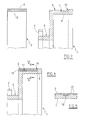
- Figure 2 shows to an enlarged scale a part of the section II-II of Figure 1.
- Figure 3 is a partial view similar to Figure 1, showing how the flexible rings are engaged with the respective retention seats in the annular structures.
- Figure 4 shows to an enlarged scale a part of the section IV-IV of Figure 3.
- Figure 5 shows a part of the section V-V of Figure 4.
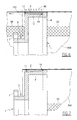
- Figure 6 is a view similar to Figure 4, showing how the printing screen is wrapped about the inextensible flexible rings, then tensioned and fixed.
- Figure 7 is a view similar to the preceding, showing a modified silk-screen printing unit of the invention, in which the section plane lies external to the position of the reference means for the correct mutual positioning of the screen and the annular structure.
- Figure 8 is a partial section similar to Figure 6, showing the disengagement of a terminal annular structure from the respective end of the printing screen.
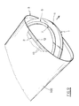
- Figure 9 is a partial perspective view showing how the previously disengaged annular structure can be extracted from the printing screen.
- Figure 10 is a schematic view showing a first method typically for storing a printing screen of the invention.
- Figure 11 is a schematic view showing a second method of storing a printing screen of the invention.
- Figure 12 is a schematic view showing a first method typically for transporting a printing screen of the invention.
- Figure 13 is a schematic view similar to the preceding showing a different transport method.
- Figure 14 is a schematic view showing a system suitable for arranging three printing screens of the invention for transport.
- the said annular structures are intended to be connected to the usual support, drive and tensioning shoulders of a likewise usual rotary silk-screen printing machine.
- Each annular structure 1 has an outer circumferential channel 5 for its connection to the respective shoulder of the rotary printing machine, and a circumferential ledge 6 for connecting the respective ring 2.
- a notch 7 In the outer lateral wall of said channel 5 there is a notch 7, the purpose of which is to set the annular structures 1 in phase during their mounting on the printing machine.
- the base wall of said sunken portion 9 is cylindrical, whereas in the alternative embodiment of Figure 7 the said base wall is shaped as a cone frustum with its minor base positioned at the base of the shoulder 10.
- said alternative embodiment facilitates the fitting and removal of the ring 2 to and from the respective sunken portion 9.
- each ring 2 consists of a thin flat strip or band of constant cross-section, formed from an inextensible elastically flexible material.
- said material is preferably a reinforced resin, for example polyethylene or polypropylene reinforced with glass fibres.
- said ring 2 can consist of thin sheet metal, for example stainless steel.
- the flat ring 2 has a thickness of for example between 2 and 3 mm, whereas in the case of metal the flat ring 2 has a thickness of for example between 0.5 and 0.9 mm.
- Said sunken portion 9, whether its base wall is cylindrical or not, and said ring 2, whether flat or not, are shaped and dimensioned such that:
- the outer diameter of the ring 2 exceeds that of the annular structure 1 by about 2 mm.
- a reference bar 12 On the inner surface of the ring 2 there is a reference bar 12 having a shape and dimensions which match those of said slot 11.
- its outer cylindrical surface is preferably provided with a plurality of identical small cuts 13 located close together and angularly equidistant, parallel to the longitudinal axis of the ring 2.
- a silk-screen printing unit of the invention is assembled as follows, using a cloth tensioning machine which is not shown as it is of normal use in this specific sector.
- the rings 2 are engaged with the sunken portions 9 of the annular structures 1 by sliding the bars 13 into the slots 11.
- the two annular structures 1 are fitted into the appropriate seats in two grooved opposing coaxial discs of the cloth tensioning machine, and are set at the correct distance apart by the rods 4.
- the silk-screen printing sheet 3 is then wrapped about the rings 2 so that its two edges 33 ( Figure 6) parallel to the axis of the annular structures 1 become superposed, the other two edges extending beyond the annular structures 1.
- Said bonding material can be a glue, such as a neoprene or polyurethane glue, or an adhesive, such as a polychloroprene adhesive or a cyanoacrylate adhesive.
- the unit obtained in this manner (annular structures + flexible tube + rods) is then fed to the subsequent operational stations where at least one permeable silk-screen printing region is formed on said flexible tube in the usual manner.
- the rods 4 are removed to release the annular structures 1, which are then extracted from the printing screen 300.
- each annular structure 1 is pushed axially inwards ( Figure 8) to disengage its sunken portion 9 from the respective ring 2, then the annular structure 1 is turned about a diameter while at the same time ovalizing the respective end portion of the screen 300, after which the annular structure can be extracted from said ovalized portion (see Figure 9).
- the reverse procedure is used to mount a printing screen 300 of the invention on two annular structures 1 associated with a rotary printing machine.
- the screen 300 can be reduced to a collapsed configuration to facilitate its storage and transport, as shown in Figures 10 to 14.
- two opposing cylindrical tubes 44 are inserted into the screen 300, one of these being hung on a horizontal rod 22 branching from a vertical support structure, so that the screen 300 assumes the shape of a vertical flattened ring.
- the prismatic tube 770 is positioned on the outside of the screen 300, however it could equally be positioned on the inside.
Landscapes
- Engineering & Computer Science (AREA)
- Mechanical Engineering (AREA)
- Printing Methods (AREA)
- Screen Printers (AREA)
- Separation Using Semi-Permeable Membranes (AREA)
- Application Of Or Painting With Fluid Materials (AREA)
- Printing Plates And Materials Therefor (AREA)
- Tubes (AREA)
- Manufacture Or Reproduction Of Printing Formes (AREA)
Applications Claiming Priority (2)
| Application Number | Priority Date | Filing Date | Title |
|---|---|---|---|
| IT1999RE000062A IT1309761B1 (it) | 1999-05-14 | 1999-05-14 | Metodo per la preparazione di schermi serigrafici cilindrici, e gruppo di stampa scomponibile corredato con detti. |
| ITRE990062 | 1999-05-14 |
Publications (3)
| Publication Number | Publication Date |
|---|---|
| EP1147891A2 true EP1147891A2 (de) | 2001-10-24 |
| EP1147891A3 EP1147891A3 (de) | 2002-04-17 |
| EP1147891B1 EP1147891B1 (de) | 2006-06-21 |
Family
ID=11399458
Family Applications (1)
| Application Number | Title | Priority Date | Filing Date |
|---|---|---|---|
| EP00201648A Expired - Lifetime EP1147891B1 (de) | 1999-05-14 | 2000-05-08 | Methode für das Vorbereiten zylindrischer Schablonen für den Siebdruck und damit ausgerüstete Sektionaldruckeinheit |
Country Status (4)
| Country | Link |
|---|---|
| EP (1) | EP1147891B1 (de) |
| AT (1) | ATE330795T1 (de) |
| DE (1) | DE60028931D1 (de) |
| IT (1) | IT1309761B1 (de) |
Cited By (2)
| Publication number | Priority date | Publication date | Assignee | Title |
|---|---|---|---|---|
| EP1719620A1 (de) * | 2005-05-04 | 2006-11-08 | Tecno - Europa S.R.L. | Zylindrische Druckschablone |
| WO2009006717A3 (en) * | 2007-07-09 | 2009-03-05 | Paulo Roberto Lourenco | System for printing of big formats in fabrics and dispositive for printing of big formats in fabrics |
Family Cites Families (2)
| Publication number | Priority date | Publication date | Assignee | Title |
|---|---|---|---|---|
| AT288446B (de) * | 1967-05-17 | 1971-03-10 | Peter Zimmer | Rundschablone |
| SE382415B (sv) * | 1974-05-30 | 1976-02-02 | Almedahls Ab | Anordning for montering av tunna cylindriska objekt |
-
1999
- 1999-05-14 IT IT1999RE000062A patent/IT1309761B1/it active
-
2000
- 2000-05-08 DE DE60028931T patent/DE60028931D1/de not_active Expired - Lifetime
- 2000-05-08 AT AT00201648T patent/ATE330795T1/de not_active IP Right Cessation
- 2000-05-08 EP EP00201648A patent/EP1147891B1/de not_active Expired - Lifetime
Cited By (2)
| Publication number | Priority date | Publication date | Assignee | Title |
|---|---|---|---|---|
| EP1719620A1 (de) * | 2005-05-04 | 2006-11-08 | Tecno - Europa S.R.L. | Zylindrische Druckschablone |
| WO2009006717A3 (en) * | 2007-07-09 | 2009-03-05 | Paulo Roberto Lourenco | System for printing of big formats in fabrics and dispositive for printing of big formats in fabrics |
Also Published As
| Publication number | Publication date |
|---|---|
| IT1309761B1 (it) | 2002-01-30 |
| EP1147891A3 (de) | 2002-04-17 |
| ITRE990062A1 (it) | 2000-11-14 |
| DE60028931D1 (de) | 2006-08-03 |
| ATE330795T1 (de) | 2006-07-15 |
| ITRE990062A0 (it) | 1999-05-14 |
| EP1147891B1 (de) | 2006-06-21 |
Similar Documents
| Publication | Publication Date | Title |
|---|---|---|
| US4688368A (en) | Method of preparing a shipment package of printing products arriving in an imbricated formation and package obtained thereby | |
| EP0492918B1 (de) | Verfahren zum Formen einer Bahn | |
| US5443003A (en) | Stretching frame for use in silkscreening | |
| DK0458666T3 (da) | Fremgangsmåde til fremstilling af en hul struktur, der blandt andet kan anvendes til opbevaring af fluider under tryk | |
| US20090134264A1 (en) | Method and device to prepare tubular winding cores | |
| EP1147891B1 (de) | Methode für das Vorbereiten zylindrischer Schablonen für den Siebdruck und damit ausgerüstete Sektionaldruckeinheit | |
| US20220409989A1 (en) | Puzzle pad and picture frame | |
| US2404162A (en) | Method of making lamp shades and similar articles | |
| US20160052746A1 (en) | Device for receiving an elastomer strand and for feeding the elastomer strand to a processing device | |
| KR101915619B1 (ko) | 프린터의 지관 클램핑 하우징 | |
| US4391415A (en) | Facilitating the exchange of a finished package with a new core | |
| KR20000005706A (ko) | 재료코일,특히스트랩하는재료코일 | |
| US20040113011A1 (en) | Reusable collapsible core | |
| HUT70133A (en) | Furniture with supporting bodies mode of laminate cardboard and process and device for producing the furniture | |
| EP1719856A1 (de) | Verschalung für prismatische säulen | |
| US5470031A (en) | Reusable waste matrix sleeve | |
| EP0816072A1 (de) | Verfahren zum Herstellen einer Rotationssiebdruckschablone | |
| CN212315040U (zh) | 在包装机处卷绕膜的装置 | |
| KR100877540B1 (ko) | 핫픽스 자동제조장치 | |
| JP2970754B2 (ja) | スリットコイルの結束方法 | |
| JP7467811B2 (ja) | 布ロールの製造方法及びその方法で製造された布ロール | |
| JP4202437B2 (ja) | 多数の平たい印刷製品を巻取りおよび巻戻しする装置 | |
| CN210853151U (zh) | 一种分体式自动放膜装置 | |
| JPS6049931A (ja) | ラジアルタイヤ第1段階成形装置 | |
| HK40023001B (en) | A method of producing a fabric roll and roll thus made |
Legal Events
| Date | Code | Title | Description |
|---|---|---|---|
| PUAI | Public reference made under article 153(3) epc to a published international application that has entered the european phase |
Free format text: ORIGINAL CODE: 0009012 |
|
| AK | Designated contracting states |
Kind code of ref document: A2 Designated state(s): AT BE CH CY DE DK ES FI FR GB GR IE IT LI LU MC NL PT SE |
|
| AX | Request for extension of the european patent |
Free format text: AL;LT;LV;MK;RO;SI |
|
| PUAL | Search report despatched |
Free format text: ORIGINAL CODE: 0009013 |
|
| AK | Designated contracting states |
Kind code of ref document: A3 Designated state(s): AT BE CH CY DE DK ES FI FR GB GR IE IT LI LU MC NL PT SE |
|
| AX | Request for extension of the european patent |
Free format text: AL;LT;LV;MK;RO;SI |
|
| 17P | Request for examination filed |
Effective date: 20020923 |
|
| AKX | Designation fees paid |
Free format text: AT BE CH CY DE DK ES FI FR GB GR IE IT LI LU MC NL PT SE |
|
| 17Q | First examination report despatched |
Effective date: 20050429 |
|
| GRAP | Despatch of communication of intention to grant a patent |
Free format text: ORIGINAL CODE: EPIDOSNIGR1 |
|
| GRAS | Grant fee paid |
Free format text: ORIGINAL CODE: EPIDOSNIGR3 |
|
| GRAA | (expected) grant |
Free format text: ORIGINAL CODE: 0009210 |
|
| RTI1 | Title (correction) |
Free format text: METHOD FOR PREPARING CYLINDRICAL SCREENS FOR SILK-SCREEN PRINTING, AND A SECTIONAL PRINTING UNIT EQUIPPED THEREWITH |
|
| AK | Designated contracting states |
Kind code of ref document: B1 Designated state(s): AT BE CH CY DE DK ES FI FR GB GR IE IT LI LU MC NL PT SE |
|
| PG25 | Lapsed in a contracting state [announced via postgrant information from national office to epo] |
Ref country code: IT Free format text: LAPSE BECAUSE OF FAILURE TO SUBMIT A TRANSLATION OF THE DESCRIPTION OR TO PAY THE FEE WITHIN THE PRESCRIBED TIME-LIMIT;WARNING: LAPSES OF ITALIAN PATENTS WITH EFFECTIVE DATE BEFORE 2007 MAY HAVE OCCURRED AT ANY TIME BEFORE 2007. THE CORRECT EFFECTIVE DATE MAY BE DIFFERENT FROM THE ONE RECORDED. Effective date: 20060621 Ref country code: CH Free format text: LAPSE BECAUSE OF FAILURE TO SUBMIT A TRANSLATION OF THE DESCRIPTION OR TO PAY THE FEE WITHIN THE PRESCRIBED TIME-LIMIT Effective date: 20060621 Ref country code: BE Free format text: LAPSE BECAUSE OF FAILURE TO SUBMIT A TRANSLATION OF THE DESCRIPTION OR TO PAY THE FEE WITHIN THE PRESCRIBED TIME-LIMIT Effective date: 20060621 Ref country code: NL Free format text: LAPSE BECAUSE OF FAILURE TO SUBMIT A TRANSLATION OF THE DESCRIPTION OR TO PAY THE FEE WITHIN THE PRESCRIBED TIME-LIMIT Effective date: 20060621 Ref country code: LI Free format text: LAPSE BECAUSE OF FAILURE TO SUBMIT A TRANSLATION OF THE DESCRIPTION OR TO PAY THE FEE WITHIN THE PRESCRIBED TIME-LIMIT Effective date: 20060621 Ref country code: FI Free format text: LAPSE BECAUSE OF FAILURE TO SUBMIT A TRANSLATION OF THE DESCRIPTION OR TO PAY THE FEE WITHIN THE PRESCRIBED TIME-LIMIT Effective date: 20060621 Ref country code: AT Free format text: LAPSE BECAUSE OF FAILURE TO SUBMIT A TRANSLATION OF THE DESCRIPTION OR TO PAY THE FEE WITHIN THE PRESCRIBED TIME-LIMIT Effective date: 20060621 |
|
| REG | Reference to a national code |
Ref country code: GB Ref legal event code: FG4D |
|
| REG | Reference to a national code |
Ref country code: CH Ref legal event code: EP |
|
| REG | Reference to a national code |
Ref country code: IE Ref legal event code: FG4D |
|
| REF | Corresponds to: |
Ref document number: 60028931 Country of ref document: DE Date of ref document: 20060803 Kind code of ref document: P |
|
| PG25 | Lapsed in a contracting state [announced via postgrant information from national office to epo] |
Ref country code: DK Free format text: LAPSE BECAUSE OF FAILURE TO SUBMIT A TRANSLATION OF THE DESCRIPTION OR TO PAY THE FEE WITHIN THE PRESCRIBED TIME-LIMIT Effective date: 20060921 Ref country code: SE Free format text: LAPSE BECAUSE OF FAILURE TO SUBMIT A TRANSLATION OF THE DESCRIPTION OR TO PAY THE FEE WITHIN THE PRESCRIBED TIME-LIMIT Effective date: 20060921 |
|
| PG25 | Lapsed in a contracting state [announced via postgrant information from national office to epo] |
Ref country code: DE Free format text: LAPSE BECAUSE OF FAILURE TO SUBMIT A TRANSLATION OF THE DESCRIPTION OR TO PAY THE FEE WITHIN THE PRESCRIBED TIME-LIMIT Effective date: 20060922 |
|
| PG25 | Lapsed in a contracting state [announced via postgrant information from national office to epo] |
Ref country code: ES Free format text: LAPSE BECAUSE OF FAILURE TO SUBMIT A TRANSLATION OF THE DESCRIPTION OR TO PAY THE FEE WITHIN THE PRESCRIBED TIME-LIMIT Effective date: 20061002 |
|
| PG25 | Lapsed in a contracting state [announced via postgrant information from national office to epo] |
Ref country code: PT Free format text: LAPSE BECAUSE OF FAILURE TO SUBMIT A TRANSLATION OF THE DESCRIPTION OR TO PAY THE FEE WITHIN THE PRESCRIBED TIME-LIMIT Effective date: 20061121 |
|
| NLV1 | Nl: lapsed or annulled due to failure to fulfill the requirements of art. 29p and 29m of the patents act | ||
| REG | Reference to a national code |
Ref country code: CH Ref legal event code: PL |
|
| PLBE | No opposition filed within time limit |
Free format text: ORIGINAL CODE: 0009261 |
|
| STAA | Information on the status of an ep patent application or granted ep patent |
Free format text: STATUS: NO OPPOSITION FILED WITHIN TIME LIMIT |
|
| EN | Fr: translation not filed | ||
| 26N | No opposition filed |
Effective date: 20070322 |
|
| GBPC | Gb: european patent ceased through non-payment of renewal fee |
Effective date: 20070508 |
|
| PG25 | Lapsed in a contracting state [announced via postgrant information from national office to epo] |
Ref country code: MC Free format text: LAPSE BECAUSE OF NON-PAYMENT OF DUE FEES Effective date: 20070531 |
|
| PG25 | Lapsed in a contracting state [announced via postgrant information from national office to epo] |
Ref country code: GR Free format text: LAPSE BECAUSE OF FAILURE TO SUBMIT A TRANSLATION OF THE DESCRIPTION OR TO PAY THE FEE WITHIN THE PRESCRIBED TIME-LIMIT Effective date: 20060922 Ref country code: FR Free format text: LAPSE BECAUSE OF FAILURE TO SUBMIT A TRANSLATION OF THE DESCRIPTION OR TO PAY THE FEE WITHIN THE PRESCRIBED TIME-LIMIT Effective date: 20070309 |
|
| PG25 | Lapsed in a contracting state [announced via postgrant information from national office to epo] |
Ref country code: IE Free format text: LAPSE BECAUSE OF NON-PAYMENT OF DUE FEES Effective date: 20070508 Ref country code: GB Free format text: LAPSE BECAUSE OF NON-PAYMENT OF DUE FEES Effective date: 20070508 |
|
| PG25 | Lapsed in a contracting state [announced via postgrant information from national office to epo] |
Ref country code: FR Free format text: LAPSE BECAUSE OF FAILURE TO SUBMIT A TRANSLATION OF THE DESCRIPTION OR TO PAY THE FEE WITHIN THE PRESCRIBED TIME-LIMIT Effective date: 20060621 |
|
| PG25 | Lapsed in a contracting state [announced via postgrant information from national office to epo] |
Ref country code: CY Free format text: LAPSE BECAUSE OF FAILURE TO SUBMIT A TRANSLATION OF THE DESCRIPTION OR TO PAY THE FEE WITHIN THE PRESCRIBED TIME-LIMIT Effective date: 20060621 Ref country code: LU Free format text: LAPSE BECAUSE OF NON-PAYMENT OF DUE FEES Effective date: 20070508 |
|
| PGFP | Annual fee paid to national office [announced via postgrant information from national office to epo] |
Ref country code: IT Payment date: 20090428 Year of fee payment: 10 |
|
| PG25 | Lapsed in a contracting state [announced via postgrant information from national office to epo] |
Ref country code: IT Free format text: LAPSE BECAUSE OF NON-PAYMENT OF DUE FEES Effective date: 20100508 |