EP1147908A2 - Procédé pour fabriquer des puzzles - Google Patents
Procédé pour fabriquer des puzzles Download PDFInfo
- Publication number
- EP1147908A2 EP1147908A2 EP00310418A EP00310418A EP1147908A2 EP 1147908 A2 EP1147908 A2 EP 1147908A2 EP 00310418 A EP00310418 A EP 00310418A EP 00310418 A EP00310418 A EP 00310418A EP 1147908 A2 EP1147908 A2 EP 1147908A2
- Authority
- EP
- European Patent Office
- Prior art keywords
- puzzle
- original
- printing
- ink jet
- base
- Prior art date
- Legal status (The legal status is an assumption and is not a legal conclusion. Google has not performed a legal analysis and makes no representation as to the accuracy of the status listed.)
- Withdrawn
Links
Images


Classifications
-
- B—PERFORMING OPERATIONS; TRANSPORTING
- B41—PRINTING; LINING MACHINES; TYPEWRITERS; STAMPS
- B41J—TYPEWRITERS; SELECTIVE PRINTING MECHANISMS, i.e. MECHANISMS PRINTING OTHERWISE THAN FROM A FORME; CORRECTION OF TYPOGRAPHICAL ERRORS
- B41J11/00—Devices or arrangements of selective printing mechanisms, e.g. ink-jet printers or thermal printers, for supporting or handling copy material in sheet or web form
- B41J11/66—Applications of cutting devices
-
- B—PERFORMING OPERATIONS; TRANSPORTING
- B41—PRINTING; LINING MACHINES; TYPEWRITERS; STAMPS
- B41J—TYPEWRITERS; SELECTIVE PRINTING MECHANISMS, i.e. MECHANISMS PRINTING OTHERWISE THAN FROM A FORME; CORRECTION OF TYPOGRAPHICAL ERRORS
- B41J11/00—Devices or arrangements of selective printing mechanisms, e.g. ink-jet printers or thermal printers, for supporting or handling copy material in sheet or web form
- B41J11/0015—Devices or arrangements of selective printing mechanisms, e.g. ink-jet printers or thermal printers, for supporting or handling copy material in sheet or web form for treating before, during or after printing or for uniform coating or laminating the copy material before or after printing
-
- B—PERFORMING OPERATIONS; TRANSPORTING
- B41—PRINTING; LINING MACHINES; TYPEWRITERS; STAMPS
- B41J—TYPEWRITERS; SELECTIVE PRINTING MECHANISMS, i.e. MECHANISMS PRINTING OTHERWISE THAN FROM A FORME; CORRECTION OF TYPOGRAPHICAL ERRORS
- B41J11/00—Devices or arrangements of selective printing mechanisms, e.g. ink-jet printers or thermal printers, for supporting or handling copy material in sheet or web form
- B41J11/0065—Means for printing without leaving a margin on at least one edge of the copy material, e.g. edge-to-edge printing
-
- B—PERFORMING OPERATIONS; TRANSPORTING
- B41—PRINTING; LINING MACHINES; TYPEWRITERS; STAMPS
- B41J—TYPEWRITERS; SELECTIVE PRINTING MECHANISMS, i.e. MECHANISMS PRINTING OTHERWISE THAN FROM A FORME; CORRECTION OF TYPOGRAPHICAL ERRORS
- B41J11/00—Devices or arrangements of selective printing mechanisms, e.g. ink-jet printers or thermal printers, for supporting or handling copy material in sheet or web form
- B41J11/0095—Detecting means for copy material, e.g. for detecting or sensing presence of copy material or its leading or trailing end
-
- B—PERFORMING OPERATIONS; TRANSPORTING
- B41—PRINTING; LINING MACHINES; TYPEWRITERS; STAMPS
- B41J—TYPEWRITERS; SELECTIVE PRINTING MECHANISMS, i.e. MECHANISMS PRINTING OTHERWISE THAN FROM A FORME; CORRECTION OF TYPOGRAPHICAL ERRORS
- B41J11/00—Devices or arrangements of selective printing mechanisms, e.g. ink-jet printers or thermal printers, for supporting or handling copy material in sheet or web form
- B41J11/20—Platen adjustments for varying the strength of impression, for a varying number of papers, for wear or for alignment, or for print gap adjustment
-
- B—PERFORMING OPERATIONS; TRANSPORTING
- B41—PRINTING; LINING MACHINES; TYPEWRITERS; STAMPS
- B41J—TYPEWRITERS; SELECTIVE PRINTING MECHANISMS, i.e. MECHANISMS PRINTING OTHERWISE THAN FROM A FORME; CORRECTION OF TYPOGRAPHICAL ERRORS
- B41J13/00—Devices or arrangements of selective printing mechanisms, e.g. ink-jet printers or thermal printers, specially adapted for supporting or handling copy material in short lengths, e.g. sheets
- B41J13/10—Sheet holders, retainers, movable guides, or stationary guides
- B41J13/14—Aprons or guides for the printing section
-
- B—PERFORMING OPERATIONS; TRANSPORTING
- B41—PRINTING; LINING MACHINES; TYPEWRITERS; STAMPS
- B41J—TYPEWRITERS; SELECTIVE PRINTING MECHANISMS, i.e. MECHANISMS PRINTING OTHERWISE THAN FROM A FORME; CORRECTION OF TYPOGRAPHICAL ERRORS
- B41J3/00—Typewriters or selective printing or marking mechanisms characterised by the purpose for which they are constructed
- B41J3/407—Typewriters or selective printing or marking mechanisms characterised by the purpose for which they are constructed for marking on special material
-
- A—HUMAN NECESSITIES
- A63—SPORTS; GAMES; AMUSEMENTS
- A63F—CARD, BOARD, OR ROULETTE GAMES; INDOOR GAMES USING SMALL MOVING PLAYING BODIES; VIDEO GAMES; GAMES NOT OTHERWISE PROVIDED FOR
- A63F9/00—Games not otherwise provided for
- A63F9/06—Patience; Other games for self-amusement
- A63F9/10—Two-dimensional [2D] jig-saw puzzles
- A63F2009/1072—Manufacturing
-
- A—HUMAN NECESSITIES
- A63—SPORTS; GAMES; AMUSEMENTS
- A63F—CARD, BOARD, OR ROULETTE GAMES; INDOOR GAMES USING SMALL MOVING PLAYING BODIES; VIDEO GAMES; GAMES NOT OTHERWISE PROVIDED FOR
- A63F9/00—Games not otherwise provided for
- A63F9/06—Patience; Other games for self-amusement
- A63F9/10—Two-dimensional [2D] jig-saw puzzles
Definitions
- jigsaw puzzles are manufactured by making an image receiving surface on the surface of an original puzzle base printing picture designs, or other puzzle material, are printed on the image receiving surface, and then, cutting and separated each piece of the puzzle.
- This manufacturing method cuts the puzzle base after the puzzle is printed on the image receiving surface. Since the cutting is the final process, a jigsaw puzzle manufacturer must use a cutting press machine in order to manufacture desirable jigsaw puzzles by printing desirable puzzle designs on the original puzzle base
- An issue of this invention is to propose a manufacturing method that can easily manufacture desirable jigsaw puzzles.
- This method prepares an original puzzle base 8, creates the image receiving layer 82 that is adequate for printing of water soluble ink on the surface 81, and then the original puzzle base 8 is cut into each puzzle piece 8(n). Then, the printed image such as picture designs is created on the image receiving layer 82 of the original puzzle base 8 by using an ink jet printer.
- desirable original jigsaw puzzles can be easily manufactured by using an ink jet printer or personal computer.
- the present invention is a jigsaw puzzle manufacturing method that uses an ink jet printer for printing on a recording medium placed on the medium transporting tray and by transporting the medium transporting tray with the recording medium through the printing position set by the ink jet head.
- the method creates the image receiving layer on the surface of the original puzzle base, then cuts the original puzzle base into each puzzle piece and then creates the printed images such as puzzle picture on the image receiving surface of the original puzzle base by transporting the original puzzle base that has been cut into each puzzle piece on the medium tray through the printing position set by the ink jet head.
- the method of this invention prints picture designs by using an ink jet printer after cutting the original puzzle paper into puzzle pieces.
- the portion of the paper that is cut along the line is depressed and the image receiving surface will be uneven.
- desirable printed images can be created on the image receiving surface by using the ink jet printer.
- a user can print desirable picture designs, or other puzzle material on the original puzzle base by using, for example, his or her personal computer or ink jet printer and produce original jigsaw puzzles.
- the original puzzle bases besides generally used bond papers, the original that are made of highly absorbent materials such as wood boards can also be used.
- the image receiving surface that is adequate for printing can be created by pasting the film that can carry the printed images made by water soluble ink on the surface of the original puzzle base.
- Very permanent image receiving surfaces can be made by forming the image receiving layer by applying emulsion adhesive.
- the printing area set by the ink jet head one size bigger than the printing area of the image receiving surface of the original puzzle base. This can prevent from not printing some parts on the edges of the original puzzle base and can create the high quality printed images in general.
- the ink jet printer used in the method of this invention will be described later by referring to the drawings. It is a system to print on the recording medium on the medium transporting tray and transporting the transporting tray through the printing position set by the ink jet head.
- Jigsaw puzzle manufacturing by using an ink jet printer is done as follows. As indicated in Fig. 7(a), first, the original puzzle base 8 is prepared. Next, as indicated in Fig. 7(b), the image receiving layer 82 that is adequate for creating the printed images of water soluble ink on the surface 81 of the original puzzle base 8 is created. This image receiving layer 82 is generally created by applying a film that can carry the picture quality printed images on the surface before the original puzzle base 8 is cut.
- the original puzzle base 8 is cut into each puzzle piece 8 (n) by cutting the image receiving layer 82 created on the original puzzle base 8.
- the printed image 83 such as puzzle picture designs, or other puzzle materials are created on the image receiving surface 82 of the original puzzle base 8 by transporting the original puzzle base 8 that has been cut into each puzzle piece 8 (n) on the medium tray through the printing position set by the ink jet head.
- the printing area set by the ink jet head that is one size bigger than the necessary printing area of the printed image 83 and to prevent some parts on the edges of the printed image 83 from not being printed.
- This manufacturing method prints picture designs, and the like by using an ink jet printer after cutting an original puzzle base into each puzzle piece.
- the portion of the paper that has been cut along the cutting line is depressed and the image receiving surface will be uneven.
- desirable printed images can be created on the image receiving surface by using the ink jet printer.
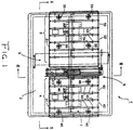
- FIGs. 1 through 6 an example of the ink jet printers that are useful for the manufacturing method of this invention.
- the ink jet printer 1 of this example has a raised frame 2 of suitable height, an ink jet head unit 3 located almost at the center of the top of this frame, a paper feeding side tray guide 4 located on the paper feeding side of this head unit 3, a paper ejecting side tray guide 5 located on the paper ejecting side of the head unit 3, and a tray transporting means or unit 6 located between the head unit 3 and the paper feeding side tray guide 5. Also, it has a medium transporting tray 7 that moves back and forth along the transporting path through the font position 31 of the head unit 3 by this transporting unit 6. If desired or preferred, the transport may be of another type using feed rollers and means for aligning the media while permitting vertical adjustment of the space between the print head and the transported media.
- Fig. 4 is a perspective that shows a medium transporting tray.
- the medium transporting tray 7 has a square board 71 with specific thickness and sprocket holes 72 and 73 that are placed in lines toward a transporting direction along both sides of this square board.
- the area surrounded by a dotted line on the flat surface of the square board 71 is a receiving surface 74 for a recording medium.
- a recording medium 8 such as a thick wood board or a thick plastic panel, and the like, is placed on this receiving surface 74.
- Figs. 5 and 6 are a perspective and a side elevation that indicate outlined construction of a tray transporting unit 6.
- the tray transporting unit 6 has a pair of sprockets 61 and 62 that can engage in the sprocket holes 72 and 73 on both sides of a medium transporting unit 7 and an interval adjustment mechanism 10 that moves these sprockets 61 and 62 to a position closer to or away from the nozzle surface 33 (see Fig. 2) of an ink jet head 32 of a head unit 3 and a driving power transmitting mechanism 9 that rotates the pair of sprockets 61 and 62.
- the sprocket 61 of this example is composed of a pair of gears 63 and 64, a belt with gears 65 that is placed over these gears, and protruding pins 66 created at a certain interval on the outer circumference of this belt with gears 65.
- the belt with gears 65 is hung toward the transporting direction of the medium transporting tray as it draws along an oval loop.
- the sprocket 62 also has the same structure and has a pair of gears 67 and 68 and a protruding pin 70 on the outer circumference of this belt with gears 69.
- a flat outer run on the top of these pairs of belts with gears 65 and 69 regulates the height of the transporting surface of the medium tray and, therefore, the position of a medium relative to the print head.
- An interval adjustment mechanism 10 has a common rotating shaft 11 that is for the gears 63 and 67 of each sprocket 61 and 62 and a common rotating shaft 12 for other gears 64 and 68 of each sprocket 61 and 62. These rotating shafts 11 and 12 are supported to rotate freely by a supporting means 13.
- the supporting means 13 has a bottom plate 131 and side plates 132 and 133 that stand perpendicularly at both sides of this bottom plate 131. Rotating shafts 11 and 12 are placed horizontally and parallel to a perpendicular direction of the transporting direction between both side plates 132 and 133.
- the center of the bottom plate 131 is supported by an elevating means 14.
- the elevating means 14 has side plates 143 and 144 with horizontal notches 141 and 142 into which the bottom plate 131 of support 13 can be inserted from the horizontal direction and a flat bottom board plate 145 that connects bottom sides of these side plates 143 and 144.
- one rotating shaft 145 is placed on the top of the horizontal notches 141 and 142 between the side plates 143 and 144.
- Top supporting rollers 146 and 147 are placed on both sides of this rotating shaft 145 to rotate freely.
- Two rotating shafts 148 and 149 are placed horizontally on the bottom of the notches 141 and 142 between the side plates 143 and 144 and bottom supporting rollers 151, 152 and 153, 154 are placed on both sides of each rotating shaft 148 and 149 to rotate freely.
- the bottom plate 131 of the supporting means that is inserted horizontally into the flat notches 141 and 142 on the side plates 143 and 144 is held by the top supporting rollers 146 and 147 and the bottom supporting rollers 151, 152 and 153, 154. Therefore, it can elevate the supporting board 13 to slide horizontally.
- One of the side plates 143 of the elevating means 14 has a part 156 that is extended to the bottom.
- a perpendicular rack 16 is formed on this part. This rack 16 engages a pinion 17 and this pinion 17 is mounted to the output shaft 181 of an elevating stepping motor 18.
- the elevating means 14 is elevated or lowered, the supporting means 13 is also elevated or lowered and the sprockets 61 and 62 of the rotating shafts 11 and 12 on this supporting means 13 will also be elevated.
- the distance between the transporting surface of the medium transporting tray that is regulated by these sprockets 61 and 62 and the ink jet head 32 of the head unit 3 will be increased or decreased. Equivalently, the head may be moved vertically toward and away from the transporting means.
- a drive transmitting mechanism rotates the sprockets 61 and 62 and includes one side of the rotating shaft 11 of the sprockets 61 and 62, a drive gear 19 fixed on the same shaft.
- This drive gear 19 engages a driving gear 20 that is placed on the side of a raised frame 2.
- the driving gear 20 is connected to a motor (not indicated in the figure) through a decelerating gear row 21. Therefore, when the driving motor is activated, the rotating shaft 11 rotates through the driving gear 20 and the following gear 19 and the sprockets 61 and 62 also rotate as one unit to transport the medium transporting tray 7 on these sprockets 61 and 62.
- both sides of two rotating shafts 11 and 12 extend outward horizontally through the side plates 132 and 133 on both sides of the supporting means 13.
- a guide 22 that has arched slots 221 and 222 and a guide 23 that arched slots 231 and 232 are placed on the outside of the side plates 132 and 133.
- Both sides of the rotating shafts 11 and 12 extend through 221, 231, and 222, 232 of each guide 22 and 23.
- the elevating gear 19 engages the driving gear 20 that is located in a fixed position.
- the gear 19 needs to be elevated along a circle trace 19a that surrounds the center of the rotation 20a of the driving gear 20.
- the rotating shafts 11 and 12 slide along the arched slots 221, 231, and 222, 232 along this arc 20b.
- the rotating shafts 11 and 12 in order to elevate the rotating shafts 11 and 12 along the arched notches, they need to move horizontally as they move through arc 20b.
- the rotating shafts 11 and 12 support the supporting means 13 to slide horizontally by the elevating means 14 with the top supporting rollers 146 and 147 and the bottom supporting rollers 151, 152, and 153, 154. Therefore, the gear 19 can be elevated while engaging with the driving gear 20.
- the ink jet printer 1 of this example elevates flat beds 4 and 5 along with the elevation of the sprockets 61 and 62.
- the transporting side that is regulated by the sprockets 61 and 62 and the transporting side of the medium transporting tray 7 by the flat beds 4 and 5 are placed on the same side.
- each flat bed 4 and 5 has tray guides 41, 42, and 51, 52 that guide the side of the medium transporting tray 7 on both sides. Also, the flat beds have multiple numbers of rollers 43 and 52 that regulate the transporting side of the medium transporting tray 7.
- the horizontal support frames 45 and 55 for the rotating shafts 44 and 54 that support rollers 43 and 53 to rotate freely are supported by perpendicular linear guides 46 and 56 to be elevated.
- the horizontal support frames 45 and 55 have brackets 47 and 57 that are extended to the bottom.
- the racks 48 and 58 are perpendicularly placed on these brackets 47 and 57.
- the pinions 50 and 60 that are placed on the output shaft of each bed elevating motor 49 and 59 engage each rack 48 and 58.
- the horizontal support frames 45 and 55 can be elevated.
- the tray transporting side that is always regulated by the sprockets 61 and 62 and the tray transporting side that is regulated by each flat bed 4 and 5 are placed at the same height.
- the ink jet printer 1 of this example can print on the recording medium 8 on the medium transporting tray by moving the medium transporting tray 7 back and forth through the font position of the print head. Since the medium transporting tray 7 is transported by the sprockets 61 and 62, this printer can easily transport heavier recording media than a friction type transporting mechanism using general paper sending rollers can transport, but general paper sending rollers may be adequate for some light weight media of different thickness.
- a gap between the recording medium 8 to be transported and the nozzle side 33 of the ink jet head 32 can and should be maintained at constant distance. Therefore, thick recording media of different thicknesses can be printed.
- the printer has the flat beds 4 and 5 located in front and back of the transporting direction. These flat beds elevate along with the sprockets 61 and 62 as one unit. Therefore, these flat beds 4 and 5 can support the medium transporting tray 7 to transport a long medium transporting tray 7.
Landscapes
- Ink Jet (AREA)
- Accessory Devices And Overall Control Thereof (AREA)
- Handling Of Sheets (AREA)
Applications Claiming Priority (2)
| Application Number | Priority Date | Filing Date | Title |
|---|---|---|---|
| US55012100A | 2000-04-17 | 2000-04-17 | |
| US550121 | 2000-04-17 |
Publications (2)
| Publication Number | Publication Date |
|---|---|
| EP1147908A2 true EP1147908A2 (fr) | 2001-10-24 |
| EP1147908A3 EP1147908A3 (fr) | 2002-10-16 |
Family
ID=24195830
Family Applications (1)
| Application Number | Title | Priority Date | Filing Date |
|---|---|---|---|
| EP00310418A Withdrawn EP1147908A3 (fr) | 2000-04-17 | 2000-11-23 | Procédé pour fabriquer des puzzles |
Country Status (2)
| Country | Link |
|---|---|
| EP (1) | EP1147908A3 (fr) |
| CA (1) | CA2320584A1 (fr) |
Cited By (3)
| Publication number | Priority date | Publication date | Assignee | Title |
|---|---|---|---|---|
| US7486841B2 (en) | 2004-04-14 | 2009-02-03 | Hasbro, Inc. | Puzzle machine and method of operating same |
| WO2011144276A1 (fr) * | 2010-05-21 | 2011-11-24 | Ravensburger Karton S.R.O. | Procédé de décoration de la surface d'éléments individuels formant ensemble un corps à trois dimensions |
| WO2011144277A1 (fr) * | 2010-05-21 | 2011-11-24 | Ravensburger Karton S.R.O. | Procédé de fabrication automatisée d'éléments individuels dont l'ensemble forme un corps en relief à surface décorée |
Family Cites Families (1)
| Publication number | Priority date | Publication date | Assignee | Title |
|---|---|---|---|---|
| JP2000190466A (ja) * | 1998-10-21 | 2000-07-11 | Master Mind:Kk | ジグソ―パズルの製造方法 |
-
2000
- 2000-09-26 CA CA 2320584 patent/CA2320584A1/fr not_active Abandoned
- 2000-11-23 EP EP00310418A patent/EP1147908A3/fr not_active Withdrawn
Non-Patent Citations (1)
| Title |
|---|
| None |
Cited By (3)
| Publication number | Priority date | Publication date | Assignee | Title |
|---|---|---|---|---|
| US7486841B2 (en) | 2004-04-14 | 2009-02-03 | Hasbro, Inc. | Puzzle machine and method of operating same |
| WO2011144276A1 (fr) * | 2010-05-21 | 2011-11-24 | Ravensburger Karton S.R.O. | Procédé de décoration de la surface d'éléments individuels formant ensemble un corps à trois dimensions |
| WO2011144277A1 (fr) * | 2010-05-21 | 2011-11-24 | Ravensburger Karton S.R.O. | Procédé de fabrication automatisée d'éléments individuels dont l'ensemble forme un corps en relief à surface décorée |
Also Published As
| Publication number | Publication date |
|---|---|
| CA2320584A1 (fr) | 2001-10-17 |
| EP1147908A3 (fr) | 2002-10-16 |
Similar Documents
| Publication | Publication Date | Title |
|---|---|---|
| EP1851654B1 (fr) | Processeur de cartes de bureau | |
| EP1371493A2 (fr) | Procédé et dispositif pour la formation d'image sur une carte | |
| CN100572228C (zh) | 片材输送装置 | |
| US5934167A (en) | Photographic material feeder apparatus | |
| CN100357100C (zh) | 使用喷墨打印机的打印系统 | |
| US6547384B2 (en) | Printing apparatus and method | |
| CA2320584A1 (fr) | Methode de fabrication d'un jeu de patience | |
| JP4199866B2 (ja) | プリンタ | |
| JP3228476B2 (ja) | 記録装置 | |
| JP7109296B2 (ja) | 印刷装置および製函機 | |
| JP2000190466A (ja) | ジグソ―パズルの製造方法 | |
| JP3701805B2 (ja) | インクジェットプリンタを用いた印刷方法 | |
| WO2000038925A1 (fr) | Procede servant a constituer un jeu de patience ou puzzle | |
| JP3523040B2 (ja) | 印字位置調整機能を備えたプリンタ装置 | |
| JPH11115274A (ja) | シート搬送装置及び画像記録装置 | |
| JP3728203B2 (ja) | インクジェット記録方法およびインクジェット記録装置 | |
| JP4704879B2 (ja) | 製本装置 | |
| JP2003287899A (ja) | 刷版供給装置 | |
| JPS62116460A (ja) | シ−ト積載装置 | |
| JP4943592B2 (ja) | インクジェットプリンタを用いた印刷システム | |
| JP2002274737A (ja) | 排紙装置 | |
| JP3785252B2 (ja) | 感光材料の振分方法 | |
| JP2000025967A (ja) | 給紙カセット | |
| EP0626332A1 (fr) | Appareil pour fabriquer des étiquettes adhésives | |
| JP2003170633A (ja) | プリンタ |
Legal Events
| Date | Code | Title | Description |
|---|---|---|---|
| PUAI | Public reference made under article 153(3) epc to a published international application that has entered the european phase |
Free format text: ORIGINAL CODE: 0009012 |
|
| AK | Designated contracting states |
Kind code of ref document: A2 Designated state(s): AT BE CH CY DE DK ES FI FR GB GR IE IT LI LU MC NL PT SE TR |
|
| AX | Request for extension of the european patent |
Free format text: AL;LT;LV;MK;RO;SI |
|
| PUAL | Search report despatched |
Free format text: ORIGINAL CODE: 0009013 |
|
| AK | Designated contracting states |
Kind code of ref document: A3 Designated state(s): AT BE CH CY DE DK ES FI FR GB GR IE IT LI LU MC NL PT SE TR |
|
| AX | Request for extension of the european patent |
Free format text: AL;LT;LV;MK;RO;SI |
|
| AKX | Designation fees paid | ||
| REG | Reference to a national code |
Ref country code: DE Ref legal event code: 8566 |
|
| STAA | Information on the status of an ep patent application or granted ep patent |
Free format text: STATUS: THE APPLICATION IS DEEMED TO BE WITHDRAWN |
|
| 18D | Application deemed to be withdrawn |
Effective date: 20021201 |