EP1147968B2 - Transpalette à cinq roues - Google Patents
Transpalette à cinq roues Download PDFInfo
- Publication number
- EP1147968B2 EP1147968B2 EP01100555A EP01100555A EP1147968B2 EP 1147968 B2 EP1147968 B2 EP 1147968B2 EP 01100555 A EP01100555 A EP 01100555A EP 01100555 A EP01100555 A EP 01100555A EP 1147968 B2 EP1147968 B2 EP 1147968B2
- Authority
- EP
- European Patent Office
- Prior art keywords
- coupling rod
- fork
- lift truck
- frame
- truck according
- Prior art date
- Legal status (The legal status is an assumption and is not a legal conclusion. Google has not performed a legal analysis and makes no representation as to the accuracy of the status listed.)
- Expired - Lifetime
Links
- 230000008878 coupling Effects 0.000 claims description 44
- 238000010168 coupling process Methods 0.000 claims description 44
- 238000005859 coupling reaction Methods 0.000 claims description 44
- 230000001419 dependent effect Effects 0.000 claims description 5
- 239000002184 metal Substances 0.000 claims description 3
- 230000006641 stabilisation Effects 0.000 claims description 3
- 238000011105 stabilization Methods 0.000 claims description 3
- 238000013016 damping Methods 0.000 claims description 2
- 238000010276 construction Methods 0.000 description 4
- 230000000694 effects Effects 0.000 description 2
- 230000003068 static effect Effects 0.000 description 2
- 230000005540 biological transmission Effects 0.000 description 1
- 230000006835 compression Effects 0.000 description 1
- 238000007906 compression Methods 0.000 description 1
- 238000005516 engineering process Methods 0.000 description 1
- 239000000284 extract Substances 0.000 description 1
- 238000000034 method Methods 0.000 description 1
- 230000004048 modification Effects 0.000 description 1
- 238000012986 modification Methods 0.000 description 1
- 230000036316 preload Effects 0.000 description 1
- 230000000087 stabilizing effect Effects 0.000 description 1
Images



Classifications
-
- B—PERFORMING OPERATIONS; TRANSPORTING
- B62—LAND VEHICLES FOR TRAVELLING OTHERWISE THAN ON RAILS
- B62B—HAND-PROPELLED VEHICLES, e.g. HAND CARTS OR PERAMBULATORS; SLEDGES
- B62B3/00—Hand carts having more than one axis carrying transport wheels; Steering devices therefor; Equipment therefor
- B62B3/04—Hand carts having more than one axis carrying transport wheels; Steering devices therefor; Equipment therefor involving means for grappling or securing in place objects to be carried; Loading or unloading equipment
- B62B3/06—Hand carts having more than one axis carrying transport wheels; Steering devices therefor; Equipment therefor involving means for grappling or securing in place objects to be carried; Loading or unloading equipment for simply clearing the load from the ground
- B62B3/0612—Hand carts having more than one axis carrying transport wheels; Steering devices therefor; Equipment therefor involving means for grappling or securing in place objects to be carried; Loading or unloading equipment for simply clearing the load from the ground power operated
-
- B—PERFORMING OPERATIONS; TRANSPORTING
- B62—LAND VEHICLES FOR TRAVELLING OTHERWISE THAN ON RAILS
- B62B—HAND-PROPELLED VEHICLES, e.g. HAND CARTS OR PERAMBULATORS; SLEDGES
- B62B2301/00—Wheel arrangements; Steering; Stability; Wheel suspension
- B62B2301/08—Wheel arrangements; Steering; Stability; Wheel suspension comprising additional wheels to increase stability
Definitions
- the invention relates to a pallet truck with a five-wheel drive according to the preamble of patent claim 1.
- Out EP 0 670 256 B 1 a lift truck has become known in which the drive wheel is mounted auchnunbeweglich and the support rollers are supported on both sides of the drive wheel via springs. The abutment of the springs are connected to each other via a coupling rod.
- Out EP 0 480 817 B 1 is known to couple the support rollers via a coupling rod with each other and to leave a central spring acting on the coupling rod.
- the spring acts on an arm on the coupling rod and generates in this way a bias and thus a corresponding contact pressure on the ground.
- Out EP 0 667 276 is known a pallet truck, in which the contact pressure of the support wheels is made dependent on the ground of the position of the mast. In the pallet truck, the mast can be moved relative to the drive part.
- Out EP 0 919 404 A2 It has become known to act on the support wheels of a fork lift truck via a spring and also the spring counteracting provide a linkage which is coupled to the lift cylinder of the fork lift truck. As the load increases, the effect of the springs is increasingly removed. This reduces the pressure of the support wheels on the ground.
- the invention has for its object to provide a pallet truck with a five-wheel drive, in which for different applications maximum traction and braking effect of the drive wheel is achieved with the greatest possible lateral stability.
- a damper element acts on the coupling rod.
- the damper element may be a rotary damper or a linearly acting hydraulic damper.
- the described coupling of the support wheels means that the support force of the coupling rod must not be varied proportionally to the recorded payload, since the load always contributes to lateral stabilization at its geometric location on the forks and leads to a load-dependent Antriebsradtik, if the drive height independently in the frame is involved.
- High-lift trucks on the other hand, require a rigid chassis structure as the lifting height increases.
- the application of force to the coupling rod must be designed in such a way that no serious drive wheel pressure loss occurs due to bumps and drive wheel wear.
- the five-wheel drive can be designed so that a maximum drive wheel traction is obtained with the greatest possible lateral stability of the truck.
- the coupling of a damper with the coupling rod also has the advantage that the damping capacity must only correspond to that of a single damper for independent support rollers, if they were provided with a damper. The effort for dampers is therefore relatively low.
- the stabilizing spring is formed by a torsion spring element, in particular a torsion bar, which is arranged in the hollow coupling rod which is non-rotatably connected at one end to the frame and at the other end non-rotatably connected to the coupling rod.
- the spring is arranged to save space. An additional space for compression springs and their bias is eliminated.
- a bearing block for the coupling rod is the torque arm for the torsion bar and received in a receiving recess of the frame.
- parallel spaced sheet metal plates may be provided on the frame, wherein one has a corresponding recess.
- an embodiment of the invention provides that a locking cylinder is provided which is adjustable in dependence on an operating parameter and which limits the Auslenkweg the support roller upwards.
- the operating parameter is preferably the lifting height of the load, alternatively also the load weight of the steering angle or the braking process can be taken or a combination of the parameters. With appropriate Lifting height can be completely locked, for example, the coupling rod and therefore prevent lifting of the support rollers.
- a force member may be provided which generates a torque on the torsion bar to produce a corresponding bias, e.g. in the form of a hydraulic cylinder, which acts on a rotatably mounted on the torsion bar lever arm.
- the bias voltage can in turn be adjusted depending on operating parameters.
- the coupling rod and the support rollers overlapping arms and the torsion bar in the coupling rod form a complete unit that can be prefabricated attached to the frame of the truck.
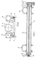
- the support wheels are mounted in bearing components 22, 24 about a vertical axis.
- the bearing components which u.a. contain a fork are not described in detail, since they are known per se.
- the bearing components 22, 24 are mounted pivotably about a horizontal axis in arms 26, 28. On the construction of the arms will be discussed in more detail in connection with the following figures.
- the arms have L-shape in plan view.
- the rear cross-sectionally approximately U-shaped section 32 forms a rear recess into which the coupling rod 30 is inserted and can be welded therein.
- the front wider portion 34 is provided with an angle profile such that the bearing member 22 and 24 of the support rollers 18, 20 can be mounted in a simple manner. This is done by means of a plate which connects the bearing member 22, 24 with the section 34 via a screw connection.
- the coupling rod 30 is hollow and inside the coupling rod, a torsion bar 36 is arranged.
- the torsion bar 36 has at the ends a square section or splines, etc., and the square section at the right end is seated in a cylindrical bearing block 38, which in turn is secured to a portion in a torque arm 40.
- the coupling rod 30 is rotatable on the bearing block 38.
- the torque arm 40 sits in a downwardly open slot 46 of the plate 10, wherein the slot is fixed downwardly by a clamping sleeve 48.
- the torque arm 40 is firmly and non-rotatably arranged in the frame.
- a square section of the torsion bar 36 in a cylindrical member 50 which is welded in the coupling rod 30.
- a countersunk screw 54 In an internally threaded bore 52 of the torsion bar 36 sits a countersunk screw 54, which in turn is secured by a lock washer 56.
- the axial bias of the torsion bar 36 can be adjusted by the screw 54.
- a hydraulic damper 54, 56 is provided, which at the top of the Inner side of the plates 10, 12 hinged and hinged at the lower end to the arm portion 32.
- a mechanical stop is provided for the support roller bearing member which prevents the support rollers from tipping too far down as they rise against the ground.
- torsion bar 36 serves as a central spring for the coupling rod 30, which counteracts a lifting of the support rollers 18, 20 due to its rotation. This movement also counteract the hydraulic damper 54, 56, the latter, however, only temporarily, while the torsion bar 36 acts statically.
- the entire structure for receiving the support rollers 18, 20 including the coupling device and the spring is a prefabricated component that can be easily attached to the frame of the pallet truck.
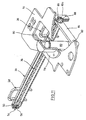
- Fig. 10 is partially to recognize a floor panel 70 of the chassis frame on which the plates 10, 12 are mounted. It can also be seen that on the bottom plate, a cylinder 72 is attached, which is supplied via a hydraulic line 74 with hydraulic medium. In the cylinder 72, a piston 76 is arranged. The piston can be moved by means of a corresponding hydraulic pressure in a defined position (end position). The free end of the piston 76 acts on the top of the arm 26, more precisely on the plate 34 and thus limits the lifting of the support rollers 18, 20.
- Fig. 11 shows a similar representation as Fig. 5 , in addition to those already in Fig. 10 bottom plate 70 can be seen.
- a cylinder 78 is fixed with a piston rod 80.
- the piston rod 80 of the hydraulic cylinder 78 is articulated to a lever arm 84 at 82 which is rotatably connected to the torsion bar 36.
- This connection is made via a bearing member 86 which is rotatably mounted in the coupling rod 30 and rotatably in a bore 88 of the modified frame plate 10a.
- the bias of the torsion bar 36, the in Fig. 11 the left end rotatably connected to the coupling rod 30 is connected.
- the bias voltage can be set to a fixed value or changed depending on operating parameters.
Landscapes
- Engineering & Computer Science (AREA)
- Chemical & Material Sciences (AREA)
- Combustion & Propulsion (AREA)
- Transportation (AREA)
- Mechanical Engineering (AREA)
- Handcart (AREA)
- Forklifts And Lifting Vehicles (AREA)
- Vehicle Body Suspensions (AREA)
Claims (10)
- Transpalette avec une châssis à cinq roues, avec une roue d'entraînement (14) immobile en hauteur, deux rouleaux d'appui (18, 20) dans la partie d'entraînement du chariot élévateur, dont chaque composant de palier repose en pivotement autour d'un axe approximativement vertical, une tige de couplage (30) couplée aux composants de palier et qui repose en rotation dans le cadre du chariot élévateur autour d'un axe horizontal et qui présente deux bras de palier (26, 28) qui sont raccordés aux composants de palier, et un ressort de stabilisation (36) central qui repose sur le cadre et agit sur la tige de couplage (30) de sorte qu'une force de pression dirigée vers le bas est transmise aux rouleaux d'appui (18, 20), où un élément amortisseur (54, 56) amortissant la rotation de la tige de couplage (30) coopère en plus avec la tige de couplage (30), caractérisé en ce que, entre le cadre et un bras situé sur la tige de couplage (30), il est disposé au moins un amortisseur hydraulique (54, 56) à action linéaire qui porte le poids des rouleaux d'appui temporairement.
- Transpalette selon la revendication 1, caractérisé en ce qu'un amortisseur de rotation coopère avec la tige de couplage (30).
- Transpalette selon la revendication 1, caractérisé en ce que l'amortisseur hydraulique est articulé sur un composant de palier (26, 28, 22, 24).
- Transpalette selon la revendication 1 à 3, caractérisé en ce que le ressort de stabilisation est formé d'un élément de ressort à torsion, en particulier d'une barre de torsion (36) qui est disposée dans la tige de couplage (30) creuse, qui est raccordée, à une extrémité, de façon anti giratoire au cadre et, à une autre extrémité, de façon anti giratoire à la tige de couplage (30).
- Transpalette selon la revendication 4, caractérisé en ce qu'un support de palier (38, 40) forme pour la tige de couplage (30) l'appui de couple pour la barre de torsion (36) et est logé de façon non rotative dans un évidement de logement (46) du cadre (10).
- Transpalette selon la revendication 1 à 5, caractérisé en ce que la tige de couplage (30) repose dans deux plaques métalliques (10, 12) du cadre espacées parallèlement.
- Transpalette selon la revendication 1 et 6, caractérisé en ce que le vérin hydraulique (54, 56) est articulé sur la plaque métallique (10, 12) affectée.
- Transpalette selon la revendication 4 à 7, quand elle dépend de la revendication 5, caractérisé en ce qu'il est prévu un organe de force qui produit un couple sur la barre de torsion (36) en vue de produire une prétension.
- Transpalette selon la revendication 8, caractérisé en ce que l'organe de force peut être réglé en fonction d'un paramètre de fonctionnement.
- Transpalette selon la revendication 8 ou 9, caractérisé en ce qu'un bras de levier est raccordé de façon anti giratoire à la barre de torsion et subit l'action d'un vérin hydraulique de prétension qui repose sur le cadre de véhicule.
Applications Claiming Priority (2)
| Application Number | Priority Date | Filing Date | Title |
|---|---|---|---|
| DE2000122400 DE10022400C5 (de) | 2000-04-20 | 2000-04-20 | Gabelhubwagen mit einem Fünfradfahrwerk |
| DE10022400 | 2000-04-20 |
Publications (4)
| Publication Number | Publication Date |
|---|---|
| EP1147968A2 EP1147968A2 (fr) | 2001-10-24 |
| EP1147968A3 EP1147968A3 (fr) | 2003-04-16 |
| EP1147968B1 EP1147968B1 (fr) | 2006-05-10 |
| EP1147968B2 true EP1147968B2 (fr) | 2009-08-26 |
Family
ID=7641204
Family Applications (1)
| Application Number | Title | Priority Date | Filing Date |
|---|---|---|---|
| EP01100555A Expired - Lifetime EP1147968B2 (fr) | 2000-04-20 | 2001-01-10 | Transpalette à cinq roues |
Country Status (2)
| Country | Link |
|---|---|
| EP (1) | EP1147968B2 (fr) |
| DE (2) | DE10022400C5 (fr) |
Cited By (1)
| Publication number | Priority date | Publication date | Assignee | Title |
|---|---|---|---|---|
| DE202015103436U1 (de) | 2015-06-30 | 2016-10-04 | Blickle Räder + Rollen GmbH u. Co. KG | Lagerung für Stützrolle |
Families Citing this family (13)
| Publication number | Priority date | Publication date | Assignee | Title |
|---|---|---|---|---|
| US7770904B2 (en) | 2005-04-14 | 2010-08-10 | Nmhg Oregon, Llc | Stability system for an industrial vehicle |
| EP2050650A1 (fr) * | 2005-04-14 | 2009-04-22 | NACCO Materials Handling Group, Inc. | Système de stabilité pour véhicule industriel |
| DE102008047022A1 (de) | 2008-09-13 | 2010-03-18 | Jungheinrich Ag | Fahrwerk für ein Flurförderzeug |
| CN103410914B (zh) * | 2013-07-19 | 2015-10-28 | 安徽力诺机械制造有限公司 | 一种叉车驱动减震系统 |
| US10315900B2 (en) | 2014-04-01 | 2019-06-11 | The Raymond Corporation | Caster wheel with constant force mechanism |
| US9593003B2 (en) | 2014-04-01 | 2017-03-14 | The Raymond Corporation | Caster wheel with constant force mechanism |
| CN104943664A (zh) * | 2015-06-30 | 2015-09-30 | 苏州先锋物流装备科技有限公司 | 铰接式平衡轮机构 |
| CN108408652A (zh) * | 2018-05-22 | 2018-08-17 | 杭叉集团股份有限公司 | 一种托盘搬运车及其辅助轮机构 |
| CN111003036B (zh) * | 2019-07-09 | 2022-06-07 | 中车长春轨道客车股份有限公司 | 着地平衡悬架结构及包括该结构的转运系统 |
| DE102021105790A1 (de) | 2021-03-10 | 2022-09-15 | Jungheinrich Aktiengesellschaft | Flurförderzeug mit mindestens einem Stützrad |
| DE102021121217A1 (de) | 2021-08-16 | 2023-02-16 | Jungheinrich Aktiengesellschaft | Grundplatte für ein autonom geführtes Flurförderzeug |
| US20230211990A1 (en) * | 2022-01-05 | 2023-07-06 | The Raymond Corporation | Torsion Bar Assembly for a Material Handling Vehicle |
| CN116639452B (zh) * | 2023-06-09 | 2026-03-27 | 东风商用车有限公司 | 一种自行小车走轮辅助装置 |
Citations (6)
| Publication number | Priority date | Publication date | Assignee | Title |
|---|---|---|---|---|
| US2660449A (en) † | 1949-01-27 | 1953-11-24 | Ford Motor Co | Wheel suspension for motor vehicles |
| DE1750706A1 (de) † | 1968-05-28 | 1971-02-25 | Ibm Deutschland | Rast- oder Klinkenhebel mit raumsparender Federanordnung |
| DE4205150A1 (de) † | 1992-02-20 | 1993-08-26 | Jungheinrich Ag | Lenkrolle fuer vier- oder mehrraedrige fahrzeuge, insbesondere flurfoerderzeuge |
| EP0584704A1 (fr) † | 1992-08-22 | 1994-03-02 | Jungheinrich Aktiengesellschaft | Véhicule à trois roues en particulier chariot de manutention |
| EP0480817B1 (fr) † | 1990-10-09 | 1995-02-22 | Loc Manutention | Chariot à plate-forme à stabilité renforcée |
| DE19753412A1 (de) † | 1997-12-02 | 1999-06-17 | Jungheinrich Ag | Gabelhubwagen mit verstellbarer Stützrolle |
Family Cites Families (13)
| Publication number | Priority date | Publication date | Assignee | Title |
|---|---|---|---|---|
| CH272974A (fr) * | 1948-07-07 | 1951-01-15 | Draize S A | Dispositif de suspension élastique pour véhicule routier, notamment pour remorque. |
| DE1948685U (de) * | 1965-04-15 | 1966-10-27 | Hans Still Ges Mit Beschraenkt | Elektro-gabelhubwagen, insbesondere elektro-gabel-hochhubwagen. |
| DE3106027C2 (de) * | 1981-02-19 | 1985-11-28 | Jungheinrich Unternehmensverwaltung Kg, 2000 Hamburg | Hublader mit einem höhenausgleichbaren Radnabenantrieb |
| DE3617026A1 (de) * | 1986-05-21 | 1987-11-26 | Jungheinrich Kg | Stapelfahrzeug mit einem schwenkbar gelagerten hubgeruest |
| FR2606765B1 (fr) * | 1986-11-13 | 1989-03-03 | Loc Manutention | Mecanisme repartiteur d'appui pour chariots de manutention et de levage notamment les transpalettes et les gerbeurs |
| FI79286C (fi) * | 1988-01-22 | 1989-12-11 | Rocla Oy | Truck. |
| MY136106A (en) | 1990-09-06 | 2008-08-29 | Novartis Ag | Synergistic composition comprising a sulfonylurea anda thiadiazolo (3,4-a)pyridazine and method of selective weed control. |
| FR2686331B1 (fr) * | 1992-01-20 | 1994-07-08 | Loc Manutention | Dispositif stabilisateur pour chariot de manutention du type transpalette ou gerbeur. |
| SE9400188L (sv) | 1994-01-21 | 1995-07-22 | Bt Ind Ab | Lyfttruck |
| FR2716878B1 (fr) | 1994-03-04 | 1996-04-26 | Mic | Chariot de manutention avec roues stabilisatrices. |
| SE509022C2 (sv) | 1997-11-28 | 1998-11-30 | Bt Ind Ab | Anordning vid stödhjul för truck |
| DE19807849C2 (de) | 1998-02-25 | 1999-12-23 | Jungheinrich Ag | Gabelhubwagen mit verstellbaren Stützrollen |
| WO2016190263A1 (fr) | 2015-05-22 | 2016-12-01 | アステラス製薬株式会社 | NOUVEAU FRAGMENT Fab D'ANTICORPS CONTRE LE NGF HUMAIN |
-
2000
- 2000-04-20 DE DE2000122400 patent/DE10022400C5/de not_active Expired - Lifetime
-
2001
- 2001-01-10 DE DE50109731T patent/DE50109731D1/de not_active Expired - Lifetime
- 2001-01-10 EP EP01100555A patent/EP1147968B2/fr not_active Expired - Lifetime
Patent Citations (6)
| Publication number | Priority date | Publication date | Assignee | Title |
|---|---|---|---|---|
| US2660449A (en) † | 1949-01-27 | 1953-11-24 | Ford Motor Co | Wheel suspension for motor vehicles |
| DE1750706A1 (de) † | 1968-05-28 | 1971-02-25 | Ibm Deutschland | Rast- oder Klinkenhebel mit raumsparender Federanordnung |
| EP0480817B1 (fr) † | 1990-10-09 | 1995-02-22 | Loc Manutention | Chariot à plate-forme à stabilité renforcée |
| DE4205150A1 (de) † | 1992-02-20 | 1993-08-26 | Jungheinrich Ag | Lenkrolle fuer vier- oder mehrraedrige fahrzeuge, insbesondere flurfoerderzeuge |
| EP0584704A1 (fr) † | 1992-08-22 | 1994-03-02 | Jungheinrich Aktiengesellschaft | Véhicule à trois roues en particulier chariot de manutention |
| DE19753412A1 (de) † | 1997-12-02 | 1999-06-17 | Jungheinrich Ag | Gabelhubwagen mit verstellbarer Stützrolle |
Cited By (2)
| Publication number | Priority date | Publication date | Assignee | Title |
|---|---|---|---|---|
| DE202015103436U1 (de) | 2015-06-30 | 2016-10-04 | Blickle Räder + Rollen GmbH u. Co. KG | Lagerung für Stützrolle |
| WO2017001432A1 (fr) | 2015-06-30 | 2017-01-05 | Blickle Räder + Rollen GmbH u. Co. KG | Support pour rouleau d'appui |
Also Published As
| Publication number | Publication date |
|---|---|
| EP1147968A2 (fr) | 2001-10-24 |
| EP1147968B1 (fr) | 2006-05-10 |
| DE10022400A1 (de) | 2001-10-31 |
| DE50109731D1 (de) | 2006-06-14 |
| EP1147968A3 (fr) | 2003-04-16 |
| DE10022400B4 (de) | 2005-06-02 |
| DE10022400C5 (de) | 2008-11-06 |
Similar Documents
| Publication | Publication Date | Title |
|---|---|---|
| DE69414359T2 (de) | Lift-Achsen-Aufhängungssystem in Form eines Parallelogramms mit Steuerung der Achsen-Schwenkeinstellung | |
| DE3904798C2 (fr) | ||
| EP1147968B2 (fr) | Transpalette à cinq roues | |
| DE60130725T2 (de) | Gabelstapler mit geringerem wenderadius und mit mitteln zur vereinfachung der wartungsarbeiten | |
| DE3106027C2 (de) | Hublader mit einem höhenausgleichbaren Radnabenantrieb | |
| EP0512550B1 (fr) | Suspension d'essieu directeur à ressort | |
| EP2517905A1 (fr) | Agencement de ressort pour suspensions de roues de véhicules automobiles | |
| EP1555238B1 (fr) | Chariot avec propulsion | |
| EP4699828A1 (fr) | Suspension à roues indépendantes orientable avec support supplémentaire | |
| EP3652002A2 (fr) | Sous-ensemble essieu pour poids-lourd, poids-lourd équipé d'au moins un tel sous-ensemble essieu et arrangement hydraulique, notamment destiné à positionner une unité positionnable réalisée sous la forme d'un arrangement de piston et cylindre | |
| DE19813796C2 (de) | Federbein mit Lenkdurchführung | |
| EP1932799B1 (fr) | Chariot de manutention | |
| DE19753412A1 (de) | Gabelhubwagen mit verstellbarer Stützrolle | |
| DE202006000552U1 (de) | Niederhubwagen | |
| DE4227954C2 (de) | Dreirädriges Flurförderzeug | |
| DE3807273C1 (fr) | ||
| DE69225225T2 (de) | Fahrzeugaufhängung | |
| EP0961726A1 (fr) | Systeme de relevage d'axe de vehicule a suspension pneumatique | |
| DE4235264B4 (de) | Hydraulische Vorderachssicherung und Blockierung für ein landwirtschaftliches Fahrzeug | |
| DE19807849C2 (de) | Gabelhubwagen mit verstellbaren Stützrollen | |
| EP0556543A2 (fr) | Roulette à pivot pour véhicules à quatre ou plus de roues, en particulier pour chariot de manutention | |
| DE19753411B4 (de) | Flurförderzeug | |
| EP4086091B1 (fr) | Automobile, ainsi que procédé de fonctionnement d'un automobile | |
| EP0530742A2 (fr) | Chariot de manutention à fourches pour palettes | |
| DE2822066C2 (de) | Einzelradaufhängung, insbesondere für Lastkraftwagen |
Legal Events
| Date | Code | Title | Description |
|---|---|---|---|
| PUAI | Public reference made under article 153(3) epc to a published international application that has entered the european phase |
Free format text: ORIGINAL CODE: 0009012 |
|
| AK | Designated contracting states |
Kind code of ref document: A2 Designated state(s): AT BE CH CY DE DK ES FI FR GB GR IE IT LI LU MC NL PT SE TR |
|
| AX | Request for extension of the european patent |
Free format text: AL;LT;LV;MK;RO;SI |
|
| PUAL | Search report despatched |
Free format text: ORIGINAL CODE: 0009013 |
|
| AK | Designated contracting states |
Designated state(s): AT BE CH CY DE DK ES FI FR GB GR IE IT LI LU MC NL PT SE TR |
|
| AX | Request for extension of the european patent |
Extension state: AL LT LV MK RO SI |
|
| 17P | Request for examination filed |
Effective date: 20030508 |
|
| AKX | Designation fees paid |
Designated state(s): DE FR GB IT NL SE |
|
| GRAP | Despatch of communication of intention to grant a patent |
Free format text: ORIGINAL CODE: EPIDOSNIGR1 |
|
| GRAS | Grant fee paid |
Free format text: ORIGINAL CODE: EPIDOSNIGR3 |
|
| GRAA | (expected) grant |
Free format text: ORIGINAL CODE: 0009210 |
|
| AK | Designated contracting states |
Kind code of ref document: B1 Designated state(s): DE FR GB IT NL SE |
|
| PG25 | Lapsed in a contracting state [announced via postgrant information from national office to epo] |
Ref country code: IT Free format text: LAPSE BECAUSE OF FAILURE TO SUBMIT A TRANSLATION OF THE DESCRIPTION OR TO PAY THE FEE WITHIN THE PRESCRIBED TIME-LIMIT;WARNING: LAPSES OF ITALIAN PATENTS WITH EFFECTIVE DATE BEFORE 2007 MAY HAVE OCCURRED AT ANY TIME BEFORE 2007. THE CORRECT EFFECTIVE DATE MAY BE DIFFERENT FROM THE ONE RECORDED. Effective date: 20060510 |
|
| REG | Reference to a national code |
Ref country code: GB Ref legal event code: FG4D Free format text: NOT ENGLISH |
|
| REG | Reference to a national code |
Ref country code: SE Ref legal event code: TRGR |
|
| REF | Corresponds to: |
Ref document number: 50109731 Country of ref document: DE Date of ref document: 20060614 Kind code of ref document: P |
|
| GBT | Gb: translation of ep patent filed (gb section 77(6)(a)/1977) |
Effective date: 20060831 |
|
| ET | Fr: translation filed | ||
| PLBI | Opposition filed |
Free format text: ORIGINAL CODE: 0009260 |
|
| 26 | Opposition filed |
Opponent name: YALE FOERDERTECHNIK HANDELSGESELLSCHAFT MBH Effective date: 20070202 |
|
| PLAX | Notice of opposition and request to file observation + time limit sent |
Free format text: ORIGINAL CODE: EPIDOSNOBS2 |
|
| NLR1 | Nl: opposition has been filed with the epo |
Opponent name: YALE FOERDERTECHNIK HANDELSGESELLSCHAFT MBH |
|
| PLBB | Reply of patent proprietor to notice(s) of opposition received |
Free format text: ORIGINAL CODE: EPIDOSNOBS3 |
|
| PLAB | Opposition data, opponent's data or that of the opponent's representative modified |
Free format text: ORIGINAL CODE: 0009299OPPO |
|
| PLBP | Opposition withdrawn |
Free format text: ORIGINAL CODE: 0009264 |
|
| PUAH | Patent maintained in amended form |
Free format text: ORIGINAL CODE: 0009272 |
|
| STAA | Information on the status of an ep patent application or granted ep patent |
Free format text: STATUS: PATENT MAINTAINED AS AMENDED |
|
| 27A | Patent maintained in amended form |
Effective date: 20090826 |
|
| AK | Designated contracting states |
Kind code of ref document: B2 Designated state(s): DE FR GB IT NL SE |
|
| NLR2 | Nl: decision of opposition |
Effective date: 20090826 |
|
| NLR3 | Nl: receipt of modified translations in the netherlands language after an opposition procedure | ||
| RAP2 | Party data changed (patent owner data changed or rights of a patent transferred) |
Owner name: JUNGHEINRICH AKTIENGESELLSCHAFT |
|
| REG | Reference to a national code |
Ref country code: SE Ref legal event code: RPEO |
|
| PGFP | Annual fee paid to national office [announced via postgrant information from national office to epo] |
Ref country code: NL Payment date: 20150126 Year of fee payment: 15 |
|
| PGFP | Annual fee paid to national office [announced via postgrant information from national office to epo] |
Ref country code: IT Payment date: 20150121 Year of fee payment: 15 |
|
| PGFP | Annual fee paid to national office [announced via postgrant information from national office to epo] |
Ref country code: GB Payment date: 20150202 Year of fee payment: 15 |
|
| REG | Reference to a national code |
Ref country code: FR Ref legal event code: PLFP Year of fee payment: 16 |
|
| GBPC | Gb: european patent ceased through non-payment of renewal fee |
Effective date: 20160110 |
|
| REG | Reference to a national code |
Ref country code: NL Ref legal event code: MM Effective date: 20160201 |
|
| PG25 | Lapsed in a contracting state [announced via postgrant information from national office to epo] |
Ref country code: GB Free format text: LAPSE BECAUSE OF NON-PAYMENT OF DUE FEES Effective date: 20160110 |
|
| PG25 | Lapsed in a contracting state [announced via postgrant information from national office to epo] |
Ref country code: NL Free format text: LAPSE BECAUSE OF NON-PAYMENT OF DUE FEES Effective date: 20160201 |
|
| PG25 | Lapsed in a contracting state [announced via postgrant information from national office to epo] |
Ref country code: IT Free format text: LAPSE BECAUSE OF NON-PAYMENT OF DUE FEES Effective date: 20160110 |
|
| REG | Reference to a national code |
Ref country code: FR Ref legal event code: PLFP Year of fee payment: 17 |
|
| REG | Reference to a national code |
Ref country code: FR Ref legal event code: PLFP Year of fee payment: 18 |
|
| PGFP | Annual fee paid to national office [announced via postgrant information from national office to epo] |
Ref country code: SE Payment date: 20200128 Year of fee payment: 20 |
|
| PGFP | Annual fee paid to national office [announced via postgrant information from national office to epo] |
Ref country code: FR Payment date: 20200128 Year of fee payment: 20 |
|
| PGFP | Annual fee paid to national office [announced via postgrant information from national office to epo] |
Ref country code: DE Payment date: 20200327 Year of fee payment: 20 |
|
| REG | Reference to a national code |
Ref country code: DE Ref legal event code: R071 Ref document number: 50109731 Country of ref document: DE |
|
| REG | Reference to a national code |
Ref country code: SE Ref legal event code: EUG |