EP1148191B1 - Antennensteuerungsschaltung mit konstantem Spitzenstrom - Google Patents
Antennensteuerungsschaltung mit konstantem Spitzenstrom Download PDFInfo
- Publication number
- EP1148191B1 EP1148191B1 EP01400960A EP01400960A EP1148191B1 EP 1148191 B1 EP1148191 B1 EP 1148191B1 EP 01400960 A EP01400960 A EP 01400960A EP 01400960 A EP01400960 A EP 01400960A EP 1148191 B1 EP1148191 B1 EP 1148191B1
- Authority
- EP
- European Patent Office
- Prior art keywords
- coil
- voltage
- magnetic field
- control signal
- periodic
- Prior art date
- Legal status (The legal status is an assumption and is not a legal conclusion. Google has not performed a legal analysis and makes no representation as to the accuracy of the status listed.)
- Expired - Lifetime
Links
Images

Classifications
-
- G—PHYSICS
- G07—CHECKING-DEVICES
- G07C—TIME OR ATTENDANCE REGISTERS; REGISTERING OR INDICATING THE WORKING OF MACHINES; GENERATING RANDOM NUMBERS; VOTING OR LOTTERY APPARATUS; ARRANGEMENTS, SYSTEMS OR APPARATUS FOR CHECKING NOT PROVIDED FOR ELSEWHERE
- G07C9/00—Individual registration on entry or exit
- G07C9/00174—Electronically operated locks; Circuits therefor; Nonmechanical keys therefor, e.g. passive or active electrical keys or other data carriers without mechanical keys
- G07C9/00309—Electronically operated locks; Circuits therefor; Nonmechanical keys therefor, e.g. passive or active electrical keys or other data carriers without mechanical keys operated with bidirectional data transmission between data carrier and locks
-
- G—PHYSICS
- G07—CHECKING-DEVICES
- G07C—TIME OR ATTENDANCE REGISTERS; REGISTERING OR INDICATING THE WORKING OF MACHINES; GENERATING RANDOM NUMBERS; VOTING OR LOTTERY APPARATUS; ARRANGEMENTS, SYSTEMS OR APPARATUS FOR CHECKING NOT PROVIDED FOR ELSEWHERE
- G07C9/00—Individual registration on entry or exit
- G07C9/00174—Electronically operated locks; Circuits therefor; Nonmechanical keys therefor, e.g. passive or active electrical keys or other data carriers without mechanical keys
- G07C2009/00753—Electronically operated locks; Circuits therefor; Nonmechanical keys therefor, e.g. passive or active electrical keys or other data carriers without mechanical keys operated by active electrical keys
- G07C2009/00769—Electronically operated locks; Circuits therefor; Nonmechanical keys therefor, e.g. passive or active electrical keys or other data carriers without mechanical keys operated by active electrical keys with data transmission performed by wireless means
- G07C2009/00777—Electronically operated locks; Circuits therefor; Nonmechanical keys therefor, e.g. passive or active electrical keys or other data carriers without mechanical keys operated by active electrical keys with data transmission performed by wireless means by induction
Definitions
- the invention relates to an electronic circuit intended to feed a magnetic field emitter coil, having a first input terminal to receive a supply voltage, a second input terminal for receive a periodic control signal, an output terminal for applying an output voltage across said transmitter coil, to convert said periodic control signal into a field Periodic magnetic emitted by the coil.
- Such a circuit is more particularly intended to power a coil transmitter forming an antenna in a so-called "hands-free" access system to a closed enclosure, this enclosure can be for example a vehicle automobile.
- a system may still be used to authorize or prohibit starting a vehicle.
- Such a system usually has a recognition device having an antenna in the form of a coil which emits a periodic magnetic field to effect a data with an identification element to be authenticated.
- the two useful features of this magnetic field are its frequency and its emission diagram.
- the circuit power supply of the transmitting coil receives a control signal at a given frequency, and applies to the transmitter coil a voltage which has the frequency of the control signal and whose amplitude is the amplitude of the vehicle battery voltage.
- the battery power supply voltage can fluctuate between 10 and 16 volts, as well, when these fluctuations are directly reflected in the amplitude of the output voltage, which is applied to the transmitting coil, it follows corresponding fluctuations in the range of the magnetic field. These fluctuations are detrimental since we want the authentication of the identification body can always be carried out in standard conditions like for example a standard minimum distance between the user and the vehicle.
- This problem can be remedied by integrating a voltage regulator in the supply circuit of the transmitting coil, to have a emission diagram of the magnetic field whose shape does not vary in depending on the fluctuations of the supply voltage.
- the defect of this solution is the increase in the cost of manufacturing the supply circuit.
- the object of the invention is to overcome these disadvantages.
- the subject of the invention is an electronic circuit designed to power a magnetic field emitting coil, having a first input terminal for receiving a supply voltage, a second terminal input to receive a periodic control signal, a terminal of output for applying an output voltage across said coil transmitter, so as to convert said periodic control signal into a periodic magnetic field emitted by the coil, characterized in that, said output voltage is a periodic signal having an identical period to the period of the control signal and a duty cycle that depends on the supply voltage so that a current flowing in the coil has a peak intensity corresponding to a reference peak intensity.
- the power supply circuit manages the peak intensity of the current that passes through the transmitter coil so that it is always equal to a reference peak intensity, thus, the range of the magnetic field emitted by the coil does not fluctuate according to the variations of the voltage provided by the battery, without having to integrate a voltage regulator to the supply circuit.
- the intensity reference peak is adjustable which allows for example to change the Magnetic field range emitted by the coil to evaluate more finely the physical location of an identification body to authenticate during an exchange of data.
- FIG. 1 is a schematic representation of a power supply circuit CA according to the invention which is connected to a field-transmitting coil Magnetic L.
- This circuit which is connected to a mass includes a first input terminal 1 for receiving a supply voltage Ubat provided by the vehicle battery and which may vary over time, a second input terminal 2 for receiving a control signal square periodical SC, and a third input terminal 3 for receiving a reference voltage Uref.
- this supply circuit comprises a terminal 4 which is intended to apply an output voltage U to the coil L magnetic field transmitter, which is connected on the one hand to this terminal 4 and on the other hand to the mass.
- the reference voltage Uref is a constant voltage corresponding to a peak current of reference Iref desired in the transmitter coil L.
- This supply circuit CA comprises a MOS transistor (not shown) which is connected between the first input terminal 1 and the output terminal 4, and which is driven by a control voltage internal to the supply circuit according to the invention.
- MOS transistor not shown
- the voltage U applied across the transmitter coil L is worth Ubat when the transistor is closed.
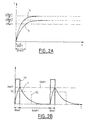
- a second curve 12 represents the establishment of the current in the coil for a second constant supply voltage Ubat2.
- this graph shows that the intensity limit of the current in the coil is Ubat / R, in the case where one applies a constant voltage Ubat at the terminals of the coil.
- the curves 11 and 12 of establishment of the currents have forms different, so that if we set a reference peak intensity, as for example Iref1, lower than Ubat1 / R and Ubat2 / R, to reach in the coil, the time required to reach this intensity has a different value ⁇ ton1, ⁇ ton2 depending on whether the constant voltage applied to coil terminals is Ubat1 or Ubat2. Quantitatively, the time for reach an intensity Iref is even longer than the voltage Ubat applied is weak.
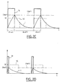
- Figure 2B shows a graph showing how a signal from square drive SC having a frequency f is converted by the circuit AC power supply according to the invention in a control voltage Uc for obtain a current I in the transmitter coil L, this current in the coil transmitter with frequency f, and for peak intensity the peak intensity of reference Iref1.
- This control voltage Uc controls the open state or closed of the MOS transistor so that it is closed when Uc is non-zero and open otherwise.
- Figure 2C which is a graph showing the same signals than those of Figure 2B, for the case where the supply voltage is not more Ubat1 but Ubat2, with Ubat2 ⁇ Ubat1, we can see that time ⁇ ton2 necessary for the current in the transmitter coil L to reach the value Iref1 is greater than the time ⁇ ton1 which appears in Figure 2B.
- the supply circuit according to the invention is capable of converting a control signal SC in a current I in the transmitter coil L having a peak intensity equal to Iref1 regardless of voltage variations power supply provided by the vehicle battery.
- the square control signal SC is converted in a periodic control voltage of rectangular shape Uc having a cyclic ratio r adapted for the duration ⁇ ton during which the voltage Ubat battery is applied to the terminals of the transmitter coil corresponds to the time required for the current in the coil issuer reaches the Iref value.
- the time ⁇ ton is set according to the supply voltage Ubat, the resistance R and the inductance L of the transmitting coil, and finally the desired peak current Iref in the transmitting coil.
- FIG 2D which is a graph representing the same signals than those of Figures 2B and 2C, for the case where the supply voltage is Ubat1 and where the reference current is worth either Iref1 but Iref2, with Iref2 ⁇ Iref1, it can be seen that the feed circuit according to the invention is capable of converting a control signal into a current in the transmitter coil having a peak intensity of Iref2.
- the supply circuit according to the invention interprets the voltage Uref to deduce the peak current of reference Iref, to deduce the corresponding cyclic ratio r.
- the circuit power supply adjusts the duty cycle of the control voltage Uc for that the peak current in the transmitting coil has the desired value.
- the supply circuit according to the invention may comprise, for example a microcontroller to calculate the ⁇ ton value according to the relation (*) or an approximate expression thereof, and order for example the opening and closing of a MOS transistor connected between the terminal input 1 and the output terminal 4.
- the microcontroller can still choose the value of ⁇ ton in a data table that it contains. So, the MOS transistor will be closed when the control voltage Uc will be no zero, during the duration ⁇ ton, so that the current I in the coil L reaches the value of the peak current Iref, then the MOS transistor will be open during the duration ⁇ toff so that the current in the sending coil decrease until the control voltage Uc is again no nothing.
- an evaluation of the supply voltage Ubat of the vehicle battery is made to calculate the ⁇ ton value and this same value is then used for the duration of an exchange of data between the recognition device and the identification device.
- the ⁇ ton value can be generated by a specialized electronic circuit.
- the form of the signal corresponding to the current in the sending coil may take the form a triangular signal with a look similar to that given in FIGS. 2A, 2B, 2C and 2D, taking into account the specific characteristics of the electronic components used.
- the broadcast at the level of the reconnaissance device whose purpose is generally to transmit a bit stream to an organ identification can for example be made according to the frequencies of 125 kHz and 133 kHz.
- the issue of a signal 125 kHz for 1 ms corresponds to the emission of a bit equal to 1
- the emission of a signal 133 kHz for 1ms corresponds to the emission a bit equal to 0, which allows the identification element to reconstitute the bitstream transmitted by the recognition device by analyzing the signal received.
- the device of recognition will emit at 125 kHz for 1 ms and then at 133 kHz for 1 ms, then at 125 kHz for 2 ms.
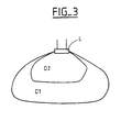
- FIG 3 which is an illustration of the magnetic field diagram transmitted by a transmitting coil comprises an emitter coil L and emission diagrams D1 and D2 corresponding, for example, to the intensities reference peaks Iref1 and Iref2.
- the radiation pattern of a magnetic field emitted by a transmitting coil is proportional to the current flowing through the coil.
- the scope of the field issued is therefore proportional to the value Iref of the selected reference peak intensity.
- Capacitive phenomena that appear between the transmitter coil and the plate may give rise to the emission of an electric field of the same frequency than the magnetic field emitted, so that the emitted field is then a electromagnetic field.
- the invention is not limited to the embodiments described above, and can also apply to any field in which we wish supplying a transmitting coil to emit a magnetic field according to a diagram that remains stable regardless of voltage fluctuations Power.
Landscapes
- Engineering & Computer Science (AREA)
- Computer Networks & Wireless Communication (AREA)
- Physics & Mathematics (AREA)
- General Physics & Mathematics (AREA)
- Charge And Discharge Circuits For Batteries Or The Like (AREA)
- Control Of Charge By Means Of Generators (AREA)
- Lock And Its Accessories (AREA)
- Selective Calling Equipment (AREA)
Claims (3)
- Elektronische Schaltung, die dazu bestimmt ist, eine Magnetfeld-Sendespule zu speisen, mit einem ersten Eingangsanschluss (1), um eine Speisespannung (Ubat) zu empfangen, einem zweiten Eingangsanschluss (2), um ein periodisches Steuersignal (SC) zu empfangen, und einem Ausgangsanschluss (4), um eine Ausgangsspannung (U) an die Anschlüsse der Sendespule (L) anzulegen, derart, dass das periodische Steuersignal in ein von der Spule ausgesendetes periodisches Magnetfeld umgesetzt wird, dadurch gekennzeichnet, dass die Ausgangsspannung (U) ein periodisches Signal ist, das eine Periode besitzt, die gleich der Periode des Steuersignals (SC) ist, und ein Tastverhältnis besitzt, das von der Speisespannung (Ubat) abhängt, damit ein in der Spule fließender Strom eine Spitzenstärke hat, die einer Referenz-Spitzenstärke entspricht.
- Elektrische Schaltung nach Anspruch 1, in der die Referenz-Spitzenstärke einstellbar ist, um die Reichweite (D1, D2) des ausgesendeten Magnetfeldes beliebig zu modifizieren.
- Sogenanntes Freihand-System, das dazu bestimmt ist, die Entriegelung von zu öffnenden Elementen eines Fahrzeugs zu steuern und/oder das Anlassen eines Fahrzeugs zu autorisieren, mit einer elektronischen Schaltung nach Anspruch 1 oder 2, in der die Speisespannung von einer Batterie des Fahrzeugs geliefert wird.
Applications Claiming Priority (2)
| Application Number | Priority Date | Filing Date | Title |
|---|---|---|---|
| FR0005043A FR2808137B1 (fr) | 2000-04-19 | 2000-04-19 | Pilote d'antenne a courant crete constant |
| FR0005043 | 2000-04-19 |
Publications (2)
| Publication Number | Publication Date |
|---|---|
| EP1148191A1 EP1148191A1 (de) | 2001-10-24 |
| EP1148191B1 true EP1148191B1 (de) | 2005-08-17 |
Family
ID=8849418
Family Applications (1)
| Application Number | Title | Priority Date | Filing Date |
|---|---|---|---|
| EP01400960A Expired - Lifetime EP1148191B1 (de) | 2000-04-19 | 2001-04-13 | Antennensteuerungsschaltung mit konstantem Spitzenstrom |
Country Status (5)
| Country | Link |
|---|---|
| US (1) | US6420837B2 (de) |
| EP (1) | EP1148191B1 (de) |
| DE (1) | DE60112645T2 (de) |
| ES (1) | ES2247032T3 (de) |
| FR (1) | FR2808137B1 (de) |
Families Citing this family (2)
| Publication number | Priority date | Publication date | Assignee | Title |
|---|---|---|---|---|
| FR2808138B1 (fr) * | 2000-04-19 | 2002-06-07 | Valeo Electronique | Pilote d'antenne emetrice de champ magnetique a circuit rlc |
| US20070149141A1 (en) * | 2003-04-25 | 2007-06-28 | Continental Teves Ag & Co. Ohg | Method for operating a transmitting device and working transmitting device |
Family Cites Families (6)
| Publication number | Priority date | Publication date | Assignee | Title |
|---|---|---|---|---|
| US5914849A (en) * | 1994-04-26 | 1999-06-22 | Kilovac Corporation | DC actuator control circuit with voltage compensation, current control and fast dropout period |
| GB2316775B (en) * | 1996-08-30 | 2000-09-06 | Caterpillar Inc | Pulse width modulation driver having peak current control |
| US6167094A (en) * | 1996-10-15 | 2000-12-26 | Siemens Aktiengesellschaft | Data transmission circuit having a station and a response circuit |
| US5831420A (en) * | 1997-04-28 | 1998-11-03 | Motorola, Inc. | Pulse load averaging power converter |
| WO1999030409A1 (en) * | 1997-12-10 | 1999-06-17 | Koninklijke Philips Electronics N.V. | Switched-mode power supply with current and voltage limitation |
| US5969515A (en) * | 1998-02-27 | 1999-10-19 | Motorola, Inc. | Apparatus and method for digital control of a power converter current |
-
2000
- 2000-04-19 FR FR0005043A patent/FR2808137B1/fr not_active Expired - Lifetime
-
2001
- 2001-04-13 DE DE60112645T patent/DE60112645T2/de not_active Expired - Lifetime
- 2001-04-13 ES ES01400960T patent/ES2247032T3/es not_active Expired - Lifetime
- 2001-04-13 EP EP01400960A patent/EP1148191B1/de not_active Expired - Lifetime
- 2001-04-18 US US09/836,389 patent/US6420837B2/en not_active Expired - Lifetime
Also Published As
| Publication number | Publication date |
|---|---|
| US6420837B2 (en) | 2002-07-16 |
| DE60112645T2 (de) | 2006-06-08 |
| US20020003500A1 (en) | 2002-01-10 |
| FR2808137B1 (fr) | 2002-06-07 |
| EP1148191A1 (de) | 2001-10-24 |
| FR2808137A1 (fr) | 2001-10-26 |
| ES2247032T3 (es) | 2006-03-01 |
| DE60112645D1 (de) | 2005-09-22 |
Similar Documents
| Publication | Publication Date | Title |
|---|---|---|
| EP1301898B1 (de) | Passiver transponder mit niedrigem energieverbrauch | |
| EP1148192B1 (de) | Steuerungsschaltung für Magnetfeldsendeantenne mit RLC-Schaltkreis | |
| EP0762147B1 (de) | Universeller induktiver Näherungsschalter | |
| EP2267647B1 (de) | Authentifizierung eines Endgeräts durch einen elektromagnetischen Transponder | |
| FR2804557A1 (fr) | Adaptation de la puissance d'emission d'un lecteur de transpondeur electromagnetique | |
| EP0356334B1 (de) | System zur gegenseitigen Informationsübertragung zwischen einem tragbaren Gegenstand, insbesondere einem Schlüssel, und einem anderen Datenträger | |
| EP1148191A1 (de) | Antennensteuerungsschaltung mit konstantem Spitzenstrom | |
| FR2776781A1 (fr) | Dispositif de controle de l'impedance ramenee sur l'antenne d'une etiquette electromagnetique | |
| EP1087332A1 (de) | Transponder für unterschiedliche Einsatzzwecke | |
| CN110979215B (zh) | 车辆用部件 | |
| FR2752651A1 (fr) | Circuit pour realiser une oscillation modulee en amplitude | |
| EP1134886B1 (de) | Verlustarmer Gleichrichter für einen Mehrphasen-Generator in Kraftfahrzeugen | |
| EP1309938B1 (de) | Antenne zum erzeugen eines elektromagnetfeldes für transponder | |
| FR3098908A1 (fr) | Capteur sans contact pour véhicule automobile | |
| FR2814130A1 (fr) | Vehicule automobile comprenant un pilote d'antenne emettrice de champ electronique alimente par un elevateur de tension | |
| EP0851563B1 (de) | Schaltnetzteileinrichtung mit kontrollierter elektromagnetischer Störung | |
| FR2930648A1 (fr) | PILOTE POUR UN SIGNAL D'EMISSION ET PROCEDE DE PILOTAGE d'UN SIGNAL D'EMISSION. | |
| EP1039408A1 (de) | Fernspeisung für einen elektromagnetischen Transponder | |
| EP1739818A1 (de) | Verfahren und Ladegerät zur Regelung des Ladestromes einer Energiequelle für ein tragbares Gerät, welches induktiv an das Ladegerät angekoppelt ist | |
| EP1170873A1 (de) | Phasekohärenter FSK-Sender | |
| FR2880746A1 (fr) | Lecteur pour la communication sans contact par induction avec un un objet portatif | |
| FR2689707A1 (fr) | Dispositif de réception et d'émission d'informations par voie radio-électrique. | |
| EP1045524A1 (de) | Funkempfänger mit niedrigen Leistungsaufnahme | |
| EP1178170A1 (de) | Fernsteuerungssystem für Kraftfahrzeuge mit einer verbesserten Empfangsantenne | |
| FR2786630A1 (fr) | Circuit de resonance, et circuit oscillant utilisant ce circuit de resonance |
Legal Events
| Date | Code | Title | Description |
|---|---|---|---|
| PUAI | Public reference made under article 153(3) epc to a published international application that has entered the european phase |
Free format text: ORIGINAL CODE: 0009012 |
|
| AK | Designated contracting states |
Kind code of ref document: A1 Designated state(s): DE ES FR GB IT Kind code of ref document: A1 Designated state(s): AT BE CH CY DE DK ES FI FR GB GR IE IT LI LU MC NL PT SE TR |
|
| AX | Request for extension of the european patent |
Free format text: AL;LT;LV;MK;RO;SI |
|
| 17P | Request for examination filed |
Effective date: 20020424 |
|
| AKX | Designation fees paid |
Free format text: DE ES FR GB IT |
|
| RAP1 | Party data changed (applicant data changed or rights of an application transferred) |
Owner name: VALEO SECURITE HABITACLE |
|
| RAP1 | Party data changed (applicant data changed or rights of an application transferred) |
Owner name: VALEO SECURITE HABITACLE S.A.S. |
|
| GRAP | Despatch of communication of intention to grant a patent |
Free format text: ORIGINAL CODE: EPIDOSNIGR1 |
|
| GRAS | Grant fee paid |
Free format text: ORIGINAL CODE: EPIDOSNIGR3 |
|
| GRAA | (expected) grant |
Free format text: ORIGINAL CODE: 0009210 |
|
| AK | Designated contracting states |
Kind code of ref document: B1 Designated state(s): DE ES FR GB IT |
|
| REG | Reference to a national code |
Ref country code: GB Ref legal event code: FG4D Free format text: NOT ENGLISH |
|
| REF | Corresponds to: |
Ref document number: 60112645 Country of ref document: DE Date of ref document: 20050922 Kind code of ref document: P |
|
| GBT | Gb: translation of ep patent filed (gb section 77(6)(a)/1977) |
Effective date: 20051109 |
|
| REG | Reference to a national code |
Ref country code: ES Ref legal event code: FG2A Ref document number: 2247032 Country of ref document: ES Kind code of ref document: T3 |
|
| PLBE | No opposition filed within time limit |
Free format text: ORIGINAL CODE: 0009261 |
|
| STAA | Information on the status of an ep patent application or granted ep patent |
Free format text: STATUS: NO OPPOSITION FILED WITHIN TIME LIMIT |
|
| 26N | No opposition filed |
Effective date: 20060518 |
|
| REG | Reference to a national code |
Ref country code: FR Ref legal event code: PLFP Year of fee payment: 16 |
|
| REG | Reference to a national code |
Ref country code: FR Ref legal event code: PLFP Year of fee payment: 17 |
|
| PGFP | Annual fee paid to national office [announced via postgrant information from national office to epo] |
Ref country code: ES Payment date: 20170508 Year of fee payment: 17 Ref country code: IT Payment date: 20170411 Year of fee payment: 17 |
|
| REG | Reference to a national code |
Ref country code: FR Ref legal event code: PLFP Year of fee payment: 18 |
|
| PG25 | Lapsed in a contracting state [announced via postgrant information from national office to epo] |
Ref country code: IT Free format text: LAPSE BECAUSE OF NON-PAYMENT OF DUE FEES Effective date: 20180413 |
|
| REG | Reference to a national code |
Ref country code: ES Ref legal event code: FD2A Effective date: 20190912 |
|
| PG25 | Lapsed in a contracting state [announced via postgrant information from national office to epo] |
Ref country code: ES Free format text: LAPSE BECAUSE OF NON-PAYMENT OF DUE FEES Effective date: 20180414 |
|
| PGFP | Annual fee paid to national office [announced via postgrant information from national office to epo] |
Ref country code: DE Payment date: 20200408 Year of fee payment: 20 Ref country code: FR Payment date: 20200430 Year of fee payment: 20 |
|
| PGFP | Annual fee paid to national office [announced via postgrant information from national office to epo] |
Ref country code: GB Payment date: 20200427 Year of fee payment: 20 |
|
| REG | Reference to a national code |
Ref country code: DE Ref legal event code: R071 Ref document number: 60112645 Country of ref document: DE |
|
| REG | Reference to a national code |
Ref country code: GB Ref legal event code: PE20 Expiry date: 20210412 |
|
| PG25 | Lapsed in a contracting state [announced via postgrant information from national office to epo] |
Ref country code: GB Free format text: LAPSE BECAUSE OF EXPIRATION OF PROTECTION Effective date: 20210412 |