EP1148221A2 - Méthode et dispositif de refroidissement des boítiers de turboréacteurs - Google Patents
Méthode et dispositif de refroidissement des boítiers de turboréacteurs Download PDFInfo
- Publication number
- EP1148221A2 EP1148221A2 EP01109019A EP01109019A EP1148221A2 EP 1148221 A2 EP1148221 A2 EP 1148221A2 EP 01109019 A EP01109019 A EP 01109019A EP 01109019 A EP01109019 A EP 01109019A EP 1148221 A2 EP1148221 A2 EP 1148221A2
- Authority
- EP
- European Patent Office
- Prior art keywords
- housing
- chamber
- cooling air
- buffer chamber
- outside
- Prior art date
- Legal status (The legal status is an assumption and is not a legal conclusion. Google has not performed a legal analysis and makes no representation as to the accuracy of the status listed.)
- Granted
Links
- 238000000034 method Methods 0.000 title claims description 13
- 238000001816 cooling Methods 0.000 claims abstract description 69
- 238000009423 ventilation Methods 0.000 description 9
- 238000010276 construction Methods 0.000 description 8
- 238000013461 design Methods 0.000 description 4
- UJCHIZDEQZMODR-BYPYZUCNSA-N (2r)-2-acetamido-3-sulfanylpropanamide Chemical compound CC(=O)N[C@@H](CS)C(N)=O UJCHIZDEQZMODR-BYPYZUCNSA-N 0.000 description 3
- 241001669680 Dormitator maculatus Species 0.000 description 3
- 230000008901 benefit Effects 0.000 description 2
- 230000001914 calming effect Effects 0.000 description 2
- 238000002485 combustion reaction Methods 0.000 description 2
- 238000011161 development Methods 0.000 description 2
- 230000002349 favourable effect Effects 0.000 description 2
- 238000012423 maintenance Methods 0.000 description 2
- 238000012986 modification Methods 0.000 description 2
- 230000004048 modification Effects 0.000 description 2
- 241000792859 Enema Species 0.000 description 1
- 230000002146 bilateral effect Effects 0.000 description 1
- 230000000694 effects Effects 0.000 description 1
- 239000007920 enema Substances 0.000 description 1
- 229940095399 enema Drugs 0.000 description 1
- 238000005516 engineering process Methods 0.000 description 1
- 238000010438 heat treatment Methods 0.000 description 1
- 238000009434 installation Methods 0.000 description 1
- 238000002955 isolation Methods 0.000 description 1
- 238000004519 manufacturing process Methods 0.000 description 1
- 230000002093 peripheral effect Effects 0.000 description 1
- 238000012546 transfer Methods 0.000 description 1
- 238000011144 upstream manufacturing Methods 0.000 description 1
Images


Classifications
-
- F—MECHANICAL ENGINEERING; LIGHTING; HEATING; WEAPONS; BLASTING
- F01—MACHINES OR ENGINES IN GENERAL; ENGINE PLANTS IN GENERAL; STEAM ENGINES
- F01D—NON-POSITIVE DISPLACEMENT MACHINES OR ENGINES, e.g. STEAM TURBINES
- F01D11/00—Preventing or minimising internal leakage of working-fluid, e.g. between stages
- F01D11/08—Preventing or minimising internal leakage of working-fluid, e.g. between stages for sealing space between rotor blade tips and stator
- F01D11/14—Adjusting or regulating tip-clearance, i.e. distance between rotor-blade tips and stator casing
- F01D11/20—Actively adjusting tip-clearance
- F01D11/24—Actively adjusting tip-clearance by selectively cooling-heating stator or rotor components
-
- B—PERFORMING OPERATIONS; TRANSPORTING
- B64—AIRCRAFT; AVIATION; COSMONAUTICS
- B64D—EQUIPMENT FOR FITTING IN OR TO AIRCRAFT; FLIGHT SUITS; PARACHUTES; ARRANGEMENT OR MOUNTING OF POWER PLANTS OR PROPULSION TRANSMISSIONS IN AIRCRAFT
- B64D33/00—Arrangement in aircraft of power plant parts or auxiliaries not otherwise provided for
- B64D33/08—Arrangement in aircraft of power plant parts or auxiliaries not otherwise provided for of power plant cooling systems
-
- F—MECHANICAL ENGINEERING; LIGHTING; HEATING; WEAPONS; BLASTING
- F01—MACHINES OR ENGINES IN GENERAL; ENGINE PLANTS IN GENERAL; STEAM ENGINES
- F01D—NON-POSITIVE DISPLACEMENT MACHINES OR ENGINES, e.g. STEAM TURBINES
- F01D25/00—Component parts, details, or accessories, not provided for in, or of interest apart from, other groups
- F01D25/08—Cooling; Heating; Heat-insulation
- F01D25/14—Casings modified therefor
-
- F—MECHANICAL ENGINEERING; LIGHTING; HEATING; WEAPONS; BLASTING
- F02—COMBUSTION ENGINES; HOT-GAS OR COMBUSTION-PRODUCT ENGINE PLANTS
- F02C—GAS-TURBINE PLANTS; AIR INTAKES FOR JET-PROPULSION PLANTS; CONTROLLING FUEL SUPPLY IN AIR-BREATHING JET-PROPULSION PLANTS
- F02C7/00—Features, components parts, details or accessories, not provided for in, or of interest apart form groups F02C1/00 - F02C6/00; Air intakes for jet-propulsion plants
- F02C7/12—Cooling of plants
- F02C7/16—Cooling of plants characterised by cooling medium
- F02C7/18—Cooling of plants characterised by cooling medium the medium being gaseous, e.g. air
-
- Y—GENERAL TAGGING OF NEW TECHNOLOGICAL DEVELOPMENTS; GENERAL TAGGING OF CROSS-SECTIONAL TECHNOLOGIES SPANNING OVER SEVERAL SECTIONS OF THE IPC; TECHNICAL SUBJECTS COVERED BY FORMER USPC CROSS-REFERENCE ART COLLECTIONS [XRACs] AND DIGESTS
- Y02—TECHNOLOGIES OR APPLICATIONS FOR MITIGATION OR ADAPTATION AGAINST CLIMATE CHANGE
- Y02T—CLIMATE CHANGE MITIGATION TECHNOLOGIES RELATED TO TRANSPORTATION
- Y02T50/00—Aeronautics or air transport
- Y02T50/60—Efficient propulsion technologies, e.g. for aircraft
Definitions
- the invention relates to a method for cooling the Turbine casing of jet engines, in which Cooling air is diverted from a bypass flow and via a provided with a shut-off line of the outside of the Housing is fed.
- the invention relates to a device for cooling the housing of turbines and Jet engines with at least one inlet channel for introduction of cooling air from a bypass flow and with at least a shut-off device assigned to the inlet channel.
- the invention is based on the object, a method and to create a device of the type mentioned at the outset, which with a simple structure and simple, more reliable Applicability both reliable cooling of each Ensure housing or housing areas of turbines and on the other hand an undesirably strong cooling at certain Avoid operating conditions.
- the cooling air is introduced into a first chamber is divided by volume in this chamber, where part of the cooling air from the first chamber to the outside of the housing is routed while another part into a second chamber downstream of the first chamber and from this applied to the outside of the housing becomes.
- the inlet channel in at least one first buffer chamber opens, which has outlet openings for supplying cooling air to the outside of the housing and to which at least one pipe is connected to the forwarding of a part the cooling air in at least one second buffer chamber with this is connected, the second buffer chamber having outlet openings for cooling air to the outside of the housing is provided.
- Both the method according to the invention and the method according to the invention Device are characterized by a number of significant Benefits from.
- the chambers form an annular space which encloses the housing areas of the turbines, it is special on simple way to control the cooling or to regulate.
- a Annulus formed not by cooling air or by one Ventilation current is applied. It follows the ability to thermally insulate the housing to a unwanted cooling or excessive cooling of the housing to avoid.
- the invention provided that the respective cooling air derived after feeding to the outside of the housing becomes.
- the individual areas of the housing fresh cold air is applied to each the desired cooling and in the area of the low pressure turbine to realize the necessary adjustment of the head gap.
- cooling air it is also advantageous for the cooling air to have throttles can be derived from the chambers. This is the flow behavior of the cooling air can be influenced in a targeted manner.
- the cooling air after striking the Outside of the case backwards into a core engine room be dissipated. So there is a good air flow available.
- the device it is particularly advantageous that at least both the first and the second buffer chamber can be partially annular.
- the engine design thus allows a configuration that can be folded away on both sides, which is particularly important in terms of ease of maintenance has an advantageous effect.
- the pipelines can be designed and installed in a favorable configuration be that a to compensate for thermal expansion Sliding connection with at least one buffer chamber is present.
- first and the second buffer chamber forward, based on the flow direction of the turbine to the housing are sealed. This can with a closed shut-off device the inside of the chambers thermally the housing isolate.
- the second buffer chamber to the rear is open to an undisturbed discharge of the cooling air cause. At least one can be in the second buffer chamber Flow guiding element can be provided to ensure a uniform Cooling air is safely applied to the outside of the housing to deliver.
- the first buffer chamber is preferably a high-pressure turbine assigned while the second buffer chamber in Area of a low pressure turbine is arranged.
- the mode of operation of the invention thus arises as follows: Via one or more NACA inlets and valves air from the bypass duct is fed into the chambers. From the or the first chambers, the cooling air is via throttle bores fed to the high pressure turbine housing. Because the first Chamber in the direction of flow as close to the front as possible Flanges the high pressure turbine housing, the flows Cooling air essentially only to the rear into the core engine room. There is a channel-shaped one above the low-pressure turbine second chamber arranged, the front tight with the housing the low pressure turbine is complete and at its rear End is open. Via the individual, pluggable pipes is this channel-like chamber with the first chamber the high pressure turbine cooling connected to cooling air for cooling to feed the low pressure turbine.
- the second chamber can be divided into subchambers so that the supplied through the pipelines Cooling air evenly around the circumference of the housing of the low-pressure turbine is distributed.
- the air therefore flows axially on the housing the low pressure turbine over and occurs at the end of the second chamber out, dealing with the ventilation air as well as with the cooling air of the first that had already escaped Chamber that cools and mixes the high pressure turbine an annular channel on the thrust nozzle of the engine in the area flows out.
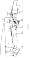
- Fig. 1 is in axial section part of a fan Jet engine shown.
- the individual components are only shown schematically, their structure is from essentially known in the prior art, so on a detailed discussion is omitted here can be.
- Fig. 1 shows a housing 1, which is a high pressure turbine 2 and a low pressure turbine 3 encloses.
- the high-pressure turbine 2 has a first chamber 6, via pipes 9 with a second chamber 7 connected is. Cooling air is supplied via an inlet duct 8 which is provided with a shut-off device (valve) 5 by one Bypass flow 4 supplied.
- valve shut-off device
- FIG. 1 also shows the following parts of the jet engine in a simplified representation: an inlet 12 for one Compressor 13, a combustion chamber 14, a thrust nozzle 15 of the core engine, a fan nozzle 16, a ventilation stream 17 with a supply flow 18, a NACA inlet 19 and an outlet gap 20 of the ventilation flow 17th
- the inventive design of the chambers 6 and 7 and the pipe 9 are in an enlarged view in the 2 and 3 are shown. 2 also shows the flow conditions through the inlet channel 8, the first chamber 6, the pipeline 9 and the second chamber 7.
- the first chamber 8 is essentially closed Chamber formed and points towards the housing 1 of the low-pressure turbine 2 several throttle recesses 10 on. Through this, as shown by the arrows, Cooling air from the housing 1. This cooling air is like represented by arrow 21, at the downstream area derived from the chamber 6 and occurs between the pipes 9 out. The housing area, which is in the piping area 9 is located, is exiting from the chamber 6 Cooling air flow 22 is applied. Part of the over the inlet duct 8 cooling air supplied by the arrow 23 flows through the plurality of pipes 9 and enters the second chamber 7.
- the shut-off device 5 can be designed in the form of a valve be the supply of cooling air through the inlet duct 8 to lock. 2 shows that for this case, the interior of the first chamber 6 and second chamber 7 form an isolation space to an undesirable To prevent cooling of the housing 1. At 28 is a carrier for the shut-off element 5 is shown.
- FIG. 3 shows the configuration in an enlarged representation of the individual pipes 9.
- the first chamber 6 is the pipeline 9 by means of a Plug connection 29 stored, which is a shift to Compensation of thermal changes in length enabled.
- the downstream end of the pipeline 9 is over a flange 30 and a screw connection 31 tight and tight connected to the wall of the second chamber 7.
- the invention relates to a method and an apparatus for cooling the housing 1 of turbines 2, 3 of Jet engines, in which cooling air from a bypass flow branched off and one with a shut-off device 5 provided inlet channel 8 fed to the outside of the housing becomes.
- the cooling air introduced into a first chamber 6 and in volume is shared. Part of the cooling air is through throttle recesses 10 passed to the housing 1 while a another part via several pipes 9 of a second chamber 7 is supplied, the housing 1 in the form of an annular space Area of a low pressure turbine 3 encloses. (Fig. 2).
Landscapes
- Engineering & Computer Science (AREA)
- Mechanical Engineering (AREA)
- General Engineering & Computer Science (AREA)
- Chemical & Material Sciences (AREA)
- Combustion & Propulsion (AREA)
- Aviation & Aerospace Engineering (AREA)
- Turbine Rotor Nozzle Sealing (AREA)
Applications Claiming Priority (2)
| Application Number | Priority Date | Filing Date | Title |
|---|---|---|---|
| DE10019437 | 2000-04-19 | ||
| DE10019437A DE10019437A1 (de) | 2000-04-19 | 2000-04-19 | Verfahren und Vorrichtung zum Kühlen der Gehäuse von Turbinen von Strahltriebwerken |
Publications (3)
| Publication Number | Publication Date |
|---|---|
| EP1148221A2 true EP1148221A2 (fr) | 2001-10-24 |
| EP1148221A3 EP1148221A3 (fr) | 2003-11-12 |
| EP1148221B1 EP1148221B1 (fr) | 2005-02-02 |
Family
ID=7639347
Family Applications (1)
| Application Number | Title | Priority Date | Filing Date |
|---|---|---|---|
| EP01109019A Expired - Lifetime EP1148221B1 (fr) | 2000-04-19 | 2001-04-11 | Méthode et dispositif de refroidissement du boítier de turboréacteurs |
Country Status (4)
| Country | Link |
|---|---|
| US (1) | US6625989B2 (fr) |
| EP (1) | EP1148221B1 (fr) |
| CA (1) | CA2344128C (fr) |
| DE (2) | DE10019437A1 (fr) |
Cited By (7)
| Publication number | Priority date | Publication date | Assignee | Title |
|---|---|---|---|---|
| FR2965010A1 (fr) * | 2010-09-17 | 2012-03-23 | Snecma | Refroidissement de la paroi exterieure d'un carter de turbine |
| EP2224099A3 (fr) * | 2009-02-26 | 2013-02-27 | Rolls-Royce Deutschland Ltd & Co KG | Réglage actif du jeu des aubes pour des turbines à gaz |
| EP2236750A3 (fr) * | 2009-03-11 | 2014-12-10 | Rolls-Royce plc | Aufprall-Kühlanordnung für einen Gasturbinenmotor |
| EP2963246A1 (fr) * | 2014-07-04 | 2016-01-06 | Rolls-Royce plc | Système de refroidissement du carter de turbine |
| FR3042817A1 (fr) * | 2015-10-23 | 2017-04-28 | Snecma | Turbomachine a double corps |
| EP2993306B1 (fr) * | 2014-09-05 | 2020-04-29 | Rolls-Royce Deutschland Ltd & Co KG | Turboreacteur dote d'un dispositif deflecteur d'air |
| FR3107563A1 (fr) * | 2020-02-25 | 2021-08-27 | Airbus Operations | Ensemble propulsif pour aeronef comportant un systeme de ventilation |
Families Citing this family (37)
| Publication number | Priority date | Publication date | Assignee | Title |
|---|---|---|---|---|
| US7434402B2 (en) * | 2005-03-29 | 2008-10-14 | Siemens Power Generation, Inc. | System for actively controlling compressor clearances |
| US7491029B2 (en) | 2005-10-14 | 2009-02-17 | United Technologies Corporation | Active clearance control system for gas turbine engines |
| US7694505B2 (en) | 2006-07-31 | 2010-04-13 | General Electric Company | Gas turbine engine assembly and method of assembling same |
| FR2923270B1 (fr) * | 2007-11-06 | 2014-01-31 | Airbus France | Turbomoteur a tuyere de flux froid adaptee |
| KR101346566B1 (ko) | 2008-10-08 | 2014-01-02 | 미츠비시 쥬고교 가부시키가이샤 | 가스 터빈 및 그 운전 방법 |
| US8181443B2 (en) * | 2008-12-10 | 2012-05-22 | Pratt & Whitney Canada Corp. | Heat exchanger to cool turbine air cooling flow |
| GB0822639D0 (en) * | 2008-12-12 | 2009-01-21 | Rolls Royce Plc | By virtue of section 39(1)(a) of the Patents Act 1977 |
| US8092153B2 (en) * | 2008-12-16 | 2012-01-10 | Pratt & Whitney Canada Corp. | Bypass air scoop for gas turbine engine |
| US7712314B1 (en) | 2009-01-21 | 2010-05-11 | Gas Turbine Efficiency Sweden Ab | Venturi cooling system |
| US8181441B2 (en) * | 2009-02-27 | 2012-05-22 | United Technologies Corporation | Controlled fan stream flow bypass |
| US8092146B2 (en) * | 2009-03-26 | 2012-01-10 | Pratt & Whitney Canada Corp. | Active tip clearance control arrangement for gas turbine engine |
| US20110171007A1 (en) * | 2009-09-25 | 2011-07-14 | James Edward Johnson | Convertible fan system |
| US20110167792A1 (en) * | 2009-09-25 | 2011-07-14 | James Edward Johnson | Adaptive engine |
| DE102010009477A1 (de) * | 2010-02-26 | 2011-09-01 | Rolls-Royce Deutschland Ltd & Co Kg | Fluggasturbinenantrieb |
| US9322293B2 (en) * | 2010-03-26 | 2016-04-26 | Snecma | Turbojet venting pipe, method for mounting one such pipe and turbojet provided with one such pipe |
| DE102010020800A1 (de) * | 2010-05-18 | 2011-11-24 | Rolls-Royce Deutschland Ltd & Co Kg | Verfahren und Vorrichtung zur Kühlluftversorgung für ein Triebwerk, insbesondere Flugtriebwerk, Gasturbine oder dergleichen |
| EP2518278A1 (fr) | 2011-04-28 | 2012-10-31 | Siemens Aktiengesellschaft | Canal de refroidissement de carter de turbine comprenant un fluide de refroidissement s'écoulant vers l'amont |
| EP2696040B1 (fr) * | 2012-08-09 | 2017-03-15 | MTU Aero Engines AG | Agencement conducteur de courant destiné au refroidissement du carter de turbines à basse pression d'un moteur à réaction à turbine à gaz |
| US9863319B2 (en) | 2012-09-28 | 2018-01-09 | United Technologies Corporation | Split-zone flow metering T-tube |
| US9938855B2 (en) * | 2014-01-31 | 2018-04-10 | Pratt & Whitney Canada Corp. | Cooling system and method for supplying a cooling gas flow |
| EP2918787B1 (fr) | 2014-03-12 | 2017-10-18 | Rolls-Royce Deutschland Ltd & Co KG | Système de guidage d'écoulement et moteur à combustion rotatif |
| DE102014217831A1 (de) | 2014-09-05 | 2016-03-10 | Rolls-Royce Deutschland Ltd & Co Kg | Vorrichtung zur Entnahme von Zapfluft und Flugzeugtriebwerk mit mindestens einer Vorrichtung zur Entnahme von Zapfluft |
| GB2533544B (en) | 2014-09-26 | 2017-02-15 | Rolls Royce Plc | A shroud segment retainer |
| DE102015206088A1 (de) * | 2015-04-02 | 2016-10-06 | Rolls-Royce Deutschland Ltd & Co Kg | Fluggasturbinentriebwerk mit Ringspaltverschlusselement |
| DE102015206091A1 (de) * | 2015-04-02 | 2016-10-06 | Rolls-Royce Deutschland Ltd & Co Kg | Fluggasturbinentriebwerk mit Ringspaltverschlusselement |
| US11434822B2 (en) | 2015-06-19 | 2022-09-06 | Raytheon Technologies Corporation | Inverse modulation of secondary bleed |
| DE102015013799A1 (de) * | 2015-10-26 | 2017-04-27 | Grenzebach Maschinenbau Gmbh | Vorrichtung und Verfahren zum Beschichten überlanger flächenhafter Substrate, insbesondere Glasscheiben, in einer Vakuum-Beschichtungsanlage |
| US10975721B2 (en) | 2016-01-12 | 2021-04-13 | Pratt & Whitney Canada Corp. | Cooled containment case using internal plenum |
| US10138752B2 (en) * | 2016-02-25 | 2018-11-27 | General Electric Company | Active HPC clearance control |
| FR3067387B1 (fr) * | 2017-06-07 | 2019-06-28 | Safran Aircraft Engines | Ecope d'alimentation en air pour l'alimentation d'un systeme de refroidissement et de controle des jeux d'une turbine |
| US10941709B2 (en) * | 2018-09-28 | 2021-03-09 | Pratt & Whitney Canada Corp. | Gas turbine engine and cooling air configuration for turbine section thereof |
| US10927761B2 (en) * | 2019-04-17 | 2021-02-23 | General Electric Company | Refreshing heat management fluid in a turbomachine |
| FR3099798B1 (fr) * | 2019-08-09 | 2021-12-03 | Safran Aircraft Engines | Ensemble pour une turbine de turbomachine |
| US10975770B1 (en) | 2019-12-05 | 2021-04-13 | Hamilton Sundstrand Corporation | Integral engine case precooler |
| US11566532B2 (en) * | 2020-12-04 | 2023-01-31 | Ge Avio S.R.L. | Turbine clearance control system |
| US11702951B1 (en) * | 2022-06-10 | 2023-07-18 | Pratt & Whitney Canada Corp. | Passive cooling system for tip clearance optimization |
| US20230417150A1 (en) * | 2022-06-22 | 2023-12-28 | Pratt & Whitney Canada Corp. | Augmented cooling for tip clearance optimization |
Citations (4)
| Publication number | Priority date | Publication date | Assignee | Title |
|---|---|---|---|---|
| US4493184A (en) | 1983-03-07 | 1985-01-15 | United Technologies Corporation | Pressurized nacelle compartment for active clearance controlled gas turbine engines |
| US5305619A (en) | 1990-03-26 | 1994-04-26 | Shima Seiki Mfg. Ltd. | Stitch increasing method and cams for flat knitting machine having stitch increasing function |
| US5392614A (en) | 1992-03-23 | 1995-02-28 | General Electric Company | Gas turbine engine cooling system |
| US5540547A (en) | 1994-06-23 | 1996-07-30 | General Electric Company | Method and apparatus for damping vibrations of external tubing of a gas turbine engine |
Family Cites Families (20)
| Publication number | Priority date | Publication date | Assignee | Title |
|---|---|---|---|---|
| US4023919A (en) * | 1974-12-19 | 1977-05-17 | General Electric Company | Thermal actuated valve for clearance control |
| US4069662A (en) * | 1975-12-05 | 1978-01-24 | United Technologies Corporation | Clearance control for gas turbine engine |
| US4019320A (en) * | 1975-12-05 | 1977-04-26 | United Technologies Corporation | External gas turbine engine cooling for clearance control |
| FR2452600A1 (fr) * | 1979-03-28 | 1980-10-24 | United Technologies Corp | Moteur a turbine a gaz avec un carter de compresseur divise longitudinalement et comportant des collecteurs s'etendant circonferentiellement autour du carter |
| US4271666A (en) * | 1979-08-20 | 1981-06-09 | Avco Corporation | Integral infrared radiation suppressor for a turbofan engine |
| US4363599A (en) * | 1979-10-31 | 1982-12-14 | General Electric Company | Clearance control |
| US4541774A (en) * | 1980-05-01 | 1985-09-17 | General Electric Company | Turbine cooling air deswirler |
| IT1137783B (it) * | 1981-08-03 | 1986-09-10 | Nuovo Pignone Spa | Scabiatore di calore integrato con la cassa statorica di una turbina a gas |
| US4526226A (en) * | 1981-08-31 | 1985-07-02 | General Electric Company | Multiple-impingement cooled structure |
| US4807433A (en) * | 1983-05-05 | 1989-02-28 | General Electric Company | Turbine cooling air modulation |
| US4512712A (en) * | 1983-08-01 | 1985-04-23 | United Technologies Corporation | Turbine stator assembly |
| US4542623A (en) * | 1983-12-23 | 1985-09-24 | United Technologies Corporation | Air cooler for providing buffer air to a bearing compartment |
| DE3546839C2 (de) * | 1985-11-19 | 1995-05-04 | Mtu Muenchen Gmbh | Gasturbinenstrahltriebwerk in Mehrwellen-Zweistrombauweise |
| FR2614073B1 (fr) * | 1987-04-15 | 1992-02-14 | Snecma | Dispositif d'ajustement en temps reel du jeu radial entre un rotor et un stator de turbomachine |
| US4901520A (en) * | 1988-08-12 | 1990-02-20 | Avco Corporation | Gas turbine pressurized cooling system |
| US5048288A (en) * | 1988-12-20 | 1991-09-17 | United Technologies Corporation | Combined turbine stator cooling and turbine tip clearance control |
| US5152666A (en) * | 1991-05-03 | 1992-10-06 | United Technologies Corporation | Stator assembly for a rotary machine |
| US5305616A (en) | 1992-03-23 | 1994-04-26 | General Electric Company | Gas turbine engine cooling system |
| US5261228A (en) * | 1992-06-25 | 1993-11-16 | General Electric Company | Apparatus for bleeding air |
| FR2751694B1 (fr) * | 1996-07-25 | 1998-09-04 | Snecma | Agencement et procede de reglage de diametre d'anneau de stator |
-
2000
- 2000-04-19 DE DE10019437A patent/DE10019437A1/de not_active Withdrawn
-
2001
- 2001-04-11 EP EP01109019A patent/EP1148221B1/fr not_active Expired - Lifetime
- 2001-04-11 DE DE50105226T patent/DE50105226D1/de not_active Expired - Lifetime
- 2001-04-17 CA CA002344128A patent/CA2344128C/fr not_active Expired - Lifetime
- 2001-04-18 US US09/836,535 patent/US6625989B2/en not_active Expired - Lifetime
Patent Citations (4)
| Publication number | Priority date | Publication date | Assignee | Title |
|---|---|---|---|---|
| US4493184A (en) | 1983-03-07 | 1985-01-15 | United Technologies Corporation | Pressurized nacelle compartment for active clearance controlled gas turbine engines |
| US5305619A (en) | 1990-03-26 | 1994-04-26 | Shima Seiki Mfg. Ltd. | Stitch increasing method and cams for flat knitting machine having stitch increasing function |
| US5392614A (en) | 1992-03-23 | 1995-02-28 | General Electric Company | Gas turbine engine cooling system |
| US5540547A (en) | 1994-06-23 | 1996-07-30 | General Electric Company | Method and apparatus for damping vibrations of external tubing of a gas turbine engine |
Cited By (11)
| Publication number | Priority date | Publication date | Assignee | Title |
|---|---|---|---|---|
| EP2224099A3 (fr) * | 2009-02-26 | 2013-02-27 | Rolls-Royce Deutschland Ltd & Co KG | Réglage actif du jeu des aubes pour des turbines à gaz |
| US8834108B2 (en) | 2009-02-26 | 2014-09-16 | Rolls-Royce Deutschland Ltd & Co Kg | Running-gap control system of an aircraft gas turbine |
| EP2236750A3 (fr) * | 2009-03-11 | 2014-12-10 | Rolls-Royce plc | Aufprall-Kühlanordnung für einen Gasturbinenmotor |
| FR2965010A1 (fr) * | 2010-09-17 | 2012-03-23 | Snecma | Refroidissement de la paroi exterieure d'un carter de turbine |
| EP2963246A1 (fr) * | 2014-07-04 | 2016-01-06 | Rolls-Royce plc | Système de refroidissement du carter de turbine |
| US9777636B2 (en) | 2014-07-04 | 2017-10-03 | Rolls-Royce Plc | Turbine case cooling system |
| EP2993306B1 (fr) * | 2014-09-05 | 2020-04-29 | Rolls-Royce Deutschland Ltd & Co KG | Turboreacteur dote d'un dispositif deflecteur d'air |
| FR3042817A1 (fr) * | 2015-10-23 | 2017-04-28 | Snecma | Turbomachine a double corps |
| FR3107563A1 (fr) * | 2020-02-25 | 2021-08-27 | Airbus Operations | Ensemble propulsif pour aeronef comportant un systeme de ventilation |
| EP3872326A1 (fr) * | 2020-02-25 | 2021-09-01 | Airbus Operations | Ensemble propulsif pour aeronef comportant un systeme de ventilation |
| US11846233B2 (en) | 2020-02-25 | 2023-12-19 | Airbus Operations Sas | Aircraft propulsion assembly having a ventilation system |
Also Published As
| Publication number | Publication date |
|---|---|
| CA2344128A1 (fr) | 2001-10-19 |
| EP1148221B1 (fr) | 2005-02-02 |
| US20020005038A1 (en) | 2002-01-17 |
| CA2344128C (fr) | 2006-10-10 |
| DE10019437A1 (de) | 2001-12-20 |
| EP1148221A3 (fr) | 2003-11-12 |
| DE50105226D1 (de) | 2005-03-10 |
| US6625989B2 (en) | 2003-09-30 |
Similar Documents
| Publication | Publication Date | Title |
|---|---|---|
| EP1148221A2 (fr) | Méthode et dispositif de refroidissement des boítiers de turboréacteurs | |
| DE2547229C2 (de) | Luftabzweigeinrichtung für einen Axialverdichter eines Gasturbinentriebwerks | |
| DE60031744T2 (de) | Turbinenbrennkammeranordnung | |
| DE69616841T2 (de) | Reinigungsverfahren für Gasturbinen-Einspritzdüse | |
| DE69311190T2 (de) | Kühlsystem für eine Gasturbine | |
| DE10303088B4 (de) | Abgasgehäuse einer Wärmekraftmaschine | |
| DE2012949A1 (de) | Wandkonstruktion und Luftzufuhrlöcher für ein Gasturbinentriebwerk | |
| DE2327243A1 (de) | Brennergehaeuse und konzentrische luftabzweigungsstruktur | |
| DE60023681T2 (de) | Kühlung der hochdruckturbinenstufe einer gasturbine | |
| DE69406071T2 (de) | Kühlungssystem für den Turbinenstator und die Turbinenrotorscheiben einer Turbomaschine | |
| DE102010016546B4 (de) | Turbinensystem und Drehsicherungszapfen für ein Turbinensystem | |
| DE3424229A1 (de) | Kuehlluftstroemungs-modulationseinrichtung fuer eine gasturbine | |
| EP2136052A1 (fr) | Turbine à turbopropulseur dotée d'un dispositif de production d'un flux d'air de refroidissement | |
| DE2532415A1 (de) | Vorrichtung zum selbsttaetigen regeln des spiels zwischen den spitzen von rotorschaufeln einer turbine und einer gegenueberliegenden wand | |
| EP1389690A1 (fr) | Vis intérieurement refroidissable | |
| DE3447740A1 (de) | Gasturbinenanlage und verfahren zu deren betreiben | |
| DE2121069A1 (de) | Gasturbinentriebwerk mit Kuhlsystem | |
| EP2148977A2 (fr) | Turbine à gaz | |
| DE2344240A1 (de) | Treibstoff-verteilungssystem | |
| WO1999063204A1 (fr) | Turbine a gaz ainsi que procede pour le refroidissement d'un etage de turbine | |
| DE2309715A1 (de) | Gasturbinentriebwerk mit flaechensteuerungseinsatz | |
| DE1626114A1 (de) | Gasturbinenstrahltriebwerk | |
| DE3023900A1 (de) | Diffusorvorrichtung und damit ausgeruestetes gasturbinentriebwerk | |
| EP0928364A1 (fr) | Compensation de la perte de pression d'une conduite d'air de refroidissement dans une installation de turbine a gaz | |
| EP1904717B1 (fr) | Element de carter conducteur de gaz chaud, enveloppe de protection d'arbre et systeme de turbine a gaz |
Legal Events
| Date | Code | Title | Description |
|---|---|---|---|
| PUAI | Public reference made under article 153(3) epc to a published international application that has entered the european phase |
Free format text: ORIGINAL CODE: 0009012 |
|
| AK | Designated contracting states |
Kind code of ref document: A2 Designated state(s): AT BE CH CY DE DK ES FI FR GB GR IE IT LI LU MC NL PT SE TR |
|
| AX | Request for extension of the european patent |
Free format text: AL;LT;LV;MK;RO;SI |
|
| PUAL | Search report despatched |
Free format text: ORIGINAL CODE: 0009013 |
|
| AK | Designated contracting states |
Kind code of ref document: A3 Designated state(s): AT BE CH CY DE DK ES FI FR GB GR IE IT LI LU MC NL PT SE TR |
|
| AX | Request for extension of the european patent |
Extension state: AL LT LV MK RO SI |
|
| RIC1 | Information provided on ipc code assigned before grant |
Ipc: 7F 01D 25/14 B Ipc: 7B 64D 33/08 B Ipc: 7F 01D 25/12 B Ipc: 7F 01D 11/24 B Ipc: 7F 02C 7/18 A |
|
| 17P | Request for examination filed |
Effective date: 20040129 |
|
| 17Q | First examination report despatched |
Effective date: 20040319 |
|
| GRAP | Despatch of communication of intention to grant a patent |
Free format text: ORIGINAL CODE: EPIDOSNIGR1 |
|
| RTI1 | Title (correction) |
Free format text: METHOD AND DEVICE TO COOL THE CASING OF TURBOJET ENGINES |
|
| AKX | Designation fees paid |
Designated state(s): DE FR GB |
|
| GRAS | Grant fee paid |
Free format text: ORIGINAL CODE: EPIDOSNIGR3 |
|
| GRAA | (expected) grant |
Free format text: ORIGINAL CODE: 0009210 |
|
| AK | Designated contracting states |
Kind code of ref document: B1 Designated state(s): DE FR GB |
|
| REG | Reference to a national code |
Ref country code: GB Ref legal event code: FG4D Free format text: NOT ENGLISH |
|
| GBT | Gb: translation of ep patent filed (gb section 77(6)(a)/1977) |
Effective date: 20050202 |
|
| REG | Reference to a national code |
Ref country code: IE Ref legal event code: FG4D Free format text: GERMAN |
|
| REF | Corresponds to: |
Ref document number: 50105226 Country of ref document: DE Date of ref document: 20050310 Kind code of ref document: P |
|
| ET | Fr: translation filed | ||
| PLBE | No opposition filed within time limit |
Free format text: ORIGINAL CODE: 0009261 |
|
| STAA | Information on the status of an ep patent application or granted ep patent |
Free format text: STATUS: NO OPPOSITION FILED WITHIN TIME LIMIT |
|
| 26N | No opposition filed |
Effective date: 20051103 |
|
| REG | Reference to a national code |
Ref country code: DE Ref legal event code: R082 Ref document number: 50105226 Country of ref document: DE Representative=s name: HOEFER & PARTNER, DE |
|
| REG | Reference to a national code |
Ref country code: DE Ref legal event code: R082 Ref document number: 50105226 Country of ref document: DE Representative=s name: HOEFER & PARTNER, DE Effective date: 20130402 Ref country code: DE Ref legal event code: R081 Ref document number: 50105226 Country of ref document: DE Owner name: ROLLS-ROYCE DEUTSCHLAND LTD & CO KG, DE Free format text: FORMER OWNER: ROLLS-ROYCE DEUTSCHLAND LTD & CO KG, 15827 BLANKENFELDE, DE Effective date: 20130402 Ref country code: DE Ref legal event code: R082 Ref document number: 50105226 Country of ref document: DE Representative=s name: HOEFER & PARTNER PATENTANWAELTE MBB, DE Effective date: 20130402 |
|
| REG | Reference to a national code |
Ref country code: FR Ref legal event code: PLFP Year of fee payment: 16 |
|
| REG | Reference to a national code |
Ref country code: FR Ref legal event code: PLFP Year of fee payment: 17 |
|
| REG | Reference to a national code |
Ref country code: FR Ref legal event code: PLFP Year of fee payment: 18 |
|
| PGFP | Annual fee paid to national office [announced via postgrant information from national office to epo] |
Ref country code: DE Payment date: 20190429 Year of fee payment: 19 |
|
| PGFP | Annual fee paid to national office [announced via postgrant information from national office to epo] |
Ref country code: FR Payment date: 20200429 Year of fee payment: 20 |
|
| PGFP | Annual fee paid to national office [announced via postgrant information from national office to epo] |
Ref country code: GB Payment date: 20200429 Year of fee payment: 20 |
|
| REG | Reference to a national code |
Ref country code: DE Ref legal event code: R119 Ref document number: 50105226 Country of ref document: DE |
|
| PG25 | Lapsed in a contracting state [announced via postgrant information from national office to epo] |
Ref country code: DE Free format text: LAPSE BECAUSE OF NON-PAYMENT OF DUE FEES Effective date: 20201103 |
|
| REG | Reference to a national code |
Ref country code: DE Ref legal event code: R082 Ref document number: 50105226 Country of ref document: DE |
|
| REG | Reference to a national code |
Ref country code: GB Ref legal event code: PE20 Expiry date: 20210410 |
|
| PG25 | Lapsed in a contracting state [announced via postgrant information from national office to epo] |
Ref country code: GB Free format text: LAPSE BECAUSE OF EXPIRATION OF PROTECTION Effective date: 20210410 |