EP1148267A2 - Verschleissfühler für einen Bremskörper - Google Patents
Verschleissfühler für einen Bremskörper Download PDFInfo
- Publication number
- EP1148267A2 EP1148267A2 EP01303522A EP01303522A EP1148267A2 EP 1148267 A2 EP1148267 A2 EP 1148267A2 EP 01303522 A EP01303522 A EP 01303522A EP 01303522 A EP01303522 A EP 01303522A EP 1148267 A2 EP1148267 A2 EP 1148267A2
- Authority
- EP
- European Patent Office
- Prior art keywords
- wear
- wire
- folded portion
- detection
- holder
- Prior art date
- Legal status (The legal status is an assumption and is not a legal conclusion. Google has not performed a legal analysis and makes no representation as to the accuracy of the status listed.)
- Granted
Links
- 238000001514 detection method Methods 0.000 title claims abstract description 111
- 239000000523 sample Substances 0.000 title claims abstract description 56
- 230000000694 effects Effects 0.000 claims description 3
- 239000002184 metal Substances 0.000 description 3
- 238000005299 abrasion Methods 0.000 description 2
- 238000010276 construction Methods 0.000 description 1
- 238000009429 electrical wiring Methods 0.000 description 1
- 238000000034 method Methods 0.000 description 1
- 230000000149 penetrating effect Effects 0.000 description 1
- 229920005989 resin Polymers 0.000 description 1
- 239000011347 resin Substances 0.000 description 1
- 229920003002 synthetic resin Polymers 0.000 description 1
- 239000000057 synthetic resin Substances 0.000 description 1
Images




Classifications
-
- F—MECHANICAL ENGINEERING; LIGHTING; HEATING; WEAPONS; BLASTING
- F16—ENGINEERING ELEMENTS AND UNITS; GENERAL MEASURES FOR PRODUCING AND MAINTAINING EFFECTIVE FUNCTIONING OF MACHINES OR INSTALLATIONS; THERMAL INSULATION IN GENERAL
- F16D—COUPLINGS FOR TRANSMITTING ROTATION; CLUTCHES; BRAKES
- F16D66/00—Arrangements for monitoring working conditions, e.g. wear, temperature
- F16D66/02—Apparatus for indicating wear
- F16D66/021—Apparatus for indicating wear using electrical detection or indication means
- F16D66/022—Apparatus for indicating wear using electrical detection or indication means indicating that a lining is worn to minimum allowable thickness
- F16D66/023—Apparatus for indicating wear using electrical detection or indication means indicating that a lining is worn to minimum allowable thickness directly sensing the position of braking members
- F16D66/024—Sensors mounted on braking members adapted to contact the brake disc or drum, e.g. wire loops severed on contact
-
- F—MECHANICAL ENGINEERING; LIGHTING; HEATING; WEAPONS; BLASTING
- F16—ENGINEERING ELEMENTS AND UNITS; GENERAL MEASURES FOR PRODUCING AND MAINTAINING EFFECTIVE FUNCTIONING OF MACHINES OR INSTALLATIONS; THERMAL INSULATION IN GENERAL
- F16D—COUPLINGS FOR TRANSMITTING ROTATION; CLUTCHES; BRAKES
- F16D66/00—Arrangements for monitoring working conditions, e.g. wear, temperature
- F16D2066/003—Position, angle or speed
Definitions
- the present invention relates to a wear detection probe for a braking member, particularly but not exclusively a braking member of a vehicle braking system, and further relates to a braking member having such a wear detection probe mounted on it and to a brake including such a braking member.
- a wear detection probe for detecting the degree of wear of a braking pad of a vehicle disclosed in US-A-5833033 has an electrical detection wire folded in the shape of a "U" embedded in a holder made of resin.
- the wear detection probe is installed on a braking pad, with the apex at the folded portion of the wire exposed and opposed to a disk rotor and with two straight line portions of the wire extending from the folded portion parallel to the axis of the disk rotor.
- the folded portion of the detection electric wire contacts the disk rotor and is abraded.
- the folded portion is broken, enabling an electrical signal to be derived.
- the two straight line portions of the wire extend to the rear side of the braking pad (opposite to the location of the disk rotor) and are connected to an external wire breakage detection circuit.
- a sufficient space for electrical wiring is not available at the rear side of the braking pad.
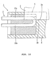
- a wear detection probe 1 as shown in present Figs. 9 and 10 has been proposed but is not thought to have been publicly used.
- This wear detection probe 1 is installed on a braking pad 4, with two straight line portions 2Sa and 2Sb of an electrical detection wire 2 parallel with a surface 3a of a disk rotor 3 and with the one straight line portion 2Sa nearer to the disk rotor 3 than the other straight line portion 2Sb.
- the straight line portions 2S By arranging the straight line portions 2S in this manner, the wire 2 is extended out of the holder 4 in the radial direction of the disk rotor 3.
- the straight line portion 2Sa nearer to the disk rotor 3 contacts the disk rotor 3 and is abraded thereby.
- the wear of the braking pad 4 reaches the limit of use, as shown in Fig. 10, the straight line portion 2Sa nearer to the disk rotor 3 is broken, which event is detected by a wear detection circuit.
- a wear detection probe for the detection of wear of a braking member which in use is mounted on the braking member and comprises a holder having a folded detection wire in a wiring path.
- the detection wire has a folded portion and two straight portions each extending from the folded portion in a direction substantially parallel to a wear surface of the holder which is worn away in use.
- the folded portion of the detection wire is located at a position nearer than the straight portions to the wear surface of the holder.
- the folded part of the detection wire in the probe of the invention is abraded by contact between the wire and the surface of the rotor and broken when the degree of wear of the braking member reaches a predetermined limit of use, thereby enabling an electrical signal indicating the wire breakage to be obtained
- a braking member comprising a body having an outer surface which is worn away in use and a wear detection probe mounted on said body, said wear detection probe having a holder having a wiring path within it and said probe further having a folded detection wire held in said wiring path and having a folded portion and two straight portions each extending from said folded portion in a direction substantially parallel to said outer surface of said braking member, said folded portion of said detection wire being located at a position nearer than said straight portions to said outer surface of said braking member.
- a brake comprising a rotor having a flat braking surface and a braking member having a body having an outer surface parallel to said braking surface which in operation is brought into contact with said braking surface to effect braking of said rotor, said outer surface of said braking member being worn away in use, said braking member comprising a wear detection probe mounted on it, said wear detection probe comprising a holder having a wiring path within it and said probe further having a folded detection wire held in said wiring path and having a folded portion and two straight portions each extending from said folded portion in a direction substantially parallel to said braking surface of said rotor, said folded portion of said detection wire being located at a position nearer to said braking surface of said rotor than said straight portions thereof.
- the distance from one straight line portion to the surface of the rotor is equal to the distance from the other straight line portion to the surface of the rotor, i.e. the straight line portions lie in one plane.
- the two straight line portions are parallel to each other.
- the two straight line portions are so disposed that the distance from the folded portion to the surface of the rotor is less than the distance from the straight line portions to the surface of the rotor.
- the spacing between the straight line portions is widened to increase the radius of curvature of the folded portion, the dimension of the path of the wire in the direction perpendicular to the surface of the rotor can be minimised, and may be equal to little more than the outer diameter of the wire.
- a minimal space is necessary for forming the region in which the two straight line portions are wired.
- the folded portion to be broken is nearer to the rotor than the two straight line portions. Accordingly, the folded portion can be broken without abrading the two straight line portions.
- the apex of the folded portion is preferably located at a position nearer to the rotor than the two straight line portions by the outer diameter of the detection wire or more. In this case, in the direction perpendicular to the surface of the rotor, the dimension of the space required for the two straight line portions and the folded portion may be only twice as large as the outer diameter of the detection wire.
- the disk brake has a disk rotor 16 and a pair (one of the pair only is shown) of braking members in the form of pads 17 which in use are moved to sandwich the disk rotor under load in its axial direction (vertical direction in Fig. 1) in a conventional manner which need not be described to achieve braking effect on the rotor.
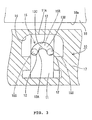
- An installing recess or hole 14 open in a direction (for example, outward in the radial direction of the disk rotor 16) parallel with the braking surface 16a of the disk rotor (surface confronting the braking pad 17) is formed on one of the braking pads 17 to accommodate the wear detection probe 10 embodying the present invention.
- the wear detection probe 10 has a holder 11 made of synthetic resin and one electrical detection wire 151ocated in a wiring path which in this embodiment lies within the holder.
- the right side in Figs. 1, 2, 5 and 6 is called the front side.
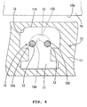
- the holder 11 has a pair of parallel right and left straight wiring path portions 12 penetrating through it.
- Each straight wiring path portion 12 is circular in section.
- the inner diameter of each straight wiring path portion 12 is equal to or slightly larger than the outer diameter of the detection wire 15.
- the right and left straight wiring path portions 12 have the same height position in the vertical direction relative to the upper surface of the holder 11.
- the holder 11 has a folded wiring path portion 13 which is open at its front side surface.
- the folded wiring path portion 13 is curved upward in front view and extends from one straight wiring path portion 12 to the other straight wiring path portion 12 semicircularly.
- the width (difference between inner diameter and outer diameter) of the folded wiring path portion 13 is equal to the inner diameter of the straight wiring path portion 12. That is, the width of the folded wiring path portion 13 is equal to the outer diameter of the detection wire 15 or slightly larger than that.
- the rear end surface of the folded wiring path portion 13 forms an inclined plane 13B descending downward toward the rear side in side view (see Fig. 1).
- the rear end surface 13C in its highest part 13A is approximately semicircular.
- the length D of the highest part 13A of the folded wiring path portion 13 in the front-to-back direction is set larger than the outer diameter of the detection wire 15.
- the vertical positional relationship between the folded wiring path portion 13 and the straight wiring path portions 12 is such that the lower end of the highest part 13A is located on a level with the upper end of the straight wiring path portions 12.
- both ends thereof are inserted into the straight wiring path portions 12 from the front of the holder 11.
- the straight line portions 15S of the wire 15 are tightened inside the straight wiring path portions 12.
- the folded portion 15R of the wire 15 accommodated in the folded wiring path portion 13 With the folded portion 15R of the wire 15 accommodated in the folded wiring path portion 13, the folded portion 15R is brought into close contact with the rear end surface of the folded wiring path portion 13 without loosening the folded portion 15R.
- the detection wire 15 wired in this manner is fixed to the holder 11 by suitable fixing means (not shown).
- the highest portion or apex of the folded portion 15R of the detection wire 15 thus installed on the holder 11 is located at a position higher than the two straight line portions 15S by the outer diameter of the detection wire 15 or by a dimension slightly larger than that.
- the wear detection probe 10 When the wear detection probe 10 is mounted on the braking pad 17 in the hole 14 thereof, the upper surface 11A of the holder 11 faces the braking surface 16a of the disk rotor 16, the two straight line portions 15S of the detection electric wire 15 are parallel to the outer, wearing surface of the pad 17 and the surface 16a (surface which contacts with the braking pad 17) of the disk rotor 16.
- the distance from one straight line portion 15S to the surface 16a of the disk rotor 16 is equal to the distance from the other straight line portion 15S to the surface 16a of the disk rotor 16, and the folded portion 15R is nearer to the surface 16a of the disk rotor than the two straight line portions 15S.
- the braking pad 17 moves together with the wear detection probe 10 toward the disk rotor, with the surfaces of the braking pad 17 and the wear detection probe 10 facing the rotor 16 parallel with each other, and contacts the surface 16a of the disk rotor with a high force.
- the surface of the braking pad 17 wears owing to the friction between the braking pad 17 and the surface 16a of the disk rotor.
- the wear of the braking pad 17 progresses.
- the upper side of the holder 11 is abraded by the contact with the surface 16a of the disk rotor 16.
- the folded portion 15R of the detection wire 15 is abraded from the high side thereof (upper side in Figs.
- the detection wire 15 is broken at the highest portion of the folded portion 15R.
- the breakage of the detection wire 15 is detected by a breakage detection circuit (not shown) connected with the detection wire 15.
- the highest portion of the folded portion 15R which is broken is located at a position nearer to the disk rotor 16 than the straight line portions 15S by the outer diameter of the detection wire 15. Therefore, the surface 16a of the disk rotor does not reach the straight line portions 15S before the folded portion 15R is broken.
- the distance from the straight line portion 15S to the surface 16a of the disk rotor 16 is equal to the distance from the other straight line portion 15S to the surface 16a of the disk rotor.
- a distance equal to the outer diameter of the detection wire 15 is only necessary for forming the space in which the two straight line portions 15S are wired. Accordingly, it is possible to make the wear detection probe 10 compact in the direction perpendicular to the surface 16a of the disk rotor 16.
- the straight wiring path portion 12 and the folded wiring path 13 would be open in the shape of a groove at the upward side thereof. In this case, there is a fear that the detection electric wire 15 becomes loose.
- the folded portion 15R to be broken is nearer to the disk rotor 16 than the two straight line portions 15S. Accordingly, the folded portion 15R can be broken without abrading the two straight line portions 15S.
- the apex of the folded portion 15R is spaced at a minimum interval from the two straight line portions 15S. That is, the folded portion 15R is located at a position nearer to the disk rotor 16 than the two straight line portions 15S by the outer diameter of the detection electric wire 15. Therefore, in the direction (height direction of the wear detection probe 10) perpendicular to the surface 16a of the disk rotor, the dimension of the space for wiring the two straight line portions 15S and the folded portion 15R can be just twice as large as the outer diameter of the detection wire 15. In this respect, it is possible to make the wear detection probe 10 compact in the direction perpendicular to the surface 16a of the disk rotor.
- Figs. 7 and 8 show a second embodiment of the invention, more particularly a disk brake braking member 20 having a flat metal plate 21 and a brake pad 22 adhesively fixed on the metal plate 21.
- the braking member 20 is mounted in the disk brake with the top surface 23 of the pad 22 parallel to the braking face of the disk rotor (not shown).
- the metal plate 21 has a stepped slot 24 adjacent a recess in one side of the pad 22.
- a wire holder 26 of a wear detection probe 25 is received in the slot 24 so that its top surface 27 is parallel to the top surface 23 of the pad 22.
- the holder 26 has grooves 28 in its sides so that it slides onto the edges of the narrower portion of the slot 24.
- the base 30 of the holder 26 is flush with the base of the plate 21.
- the holder 26 has within it a wiring path 31 of the same shape as the wiring path 15S, 15R of the embodiment of Figs. 1 to 6, with an electrical detection wire (not shown in Figs. 7 and 8) lying in the wiring path in the manner shown in Figs. 1 to 6. Although in this embodiment the holder 26 is alongside the wear surface 23 of the pad, rather than embedded in the pad as in Figs. 1 to 6, the method of operation is the same.
Landscapes
- Engineering & Computer Science (AREA)
- General Engineering & Computer Science (AREA)
- Mechanical Engineering (AREA)
- Braking Arrangements (AREA)
Applications Claiming Priority (2)
| Application Number | Priority Date | Filing Date | Title |
|---|---|---|---|
| JP2000121373A JP4254006B2 (ja) | 2000-04-21 | 2000-04-21 | 制動片の摩耗検知プローブ |
| JP2000121373 | 2000-04-21 |
Publications (3)
| Publication Number | Publication Date |
|---|---|
| EP1148267A2 true EP1148267A2 (de) | 2001-10-24 |
| EP1148267A3 EP1148267A3 (de) | 2003-10-08 |
| EP1148267B1 EP1148267B1 (de) | 2005-06-29 |
Family
ID=18632033
Family Applications (1)
| Application Number | Title | Priority Date | Filing Date |
|---|---|---|---|
| EP01303522A Expired - Lifetime EP1148267B1 (de) | 2000-04-21 | 2001-04-18 | Verschleissfühler für einen Bremskörper |
Country Status (5)
| Country | Link |
|---|---|
| US (1) | US6719102B2 (de) |
| EP (1) | EP1148267B1 (de) |
| JP (1) | JP4254006B2 (de) |
| CN (1) | CN100476231C (de) |
| DE (1) | DE60111674T2 (de) |
Cited By (7)
| Publication number | Priority date | Publication date | Assignee | Title |
|---|---|---|---|---|
| WO2006037831A1 (es) * | 2004-10-01 | 2006-04-13 | Metro De Madrid, S.A. | Detector de desgaste de zapatas o pastillas de freno de aplicación preferente a frenos de vehiculos ferroviarios |
| EP1826451A1 (de) * | 2006-02-27 | 2007-08-29 | Compagnie Plastic Omnium | Ansatzmuffe einer zweidrähtigen Verschleißwarnanzeige, die mit einem Bremsklotz eines Kraftfahrzeugs verbunden werden soll |
| ITTO20100013A1 (it) * | 2010-01-13 | 2011-07-14 | I C P Srl | Rilevatore d'usura per un organo di frenatura di un veicolo |
| EP2630386B1 (de) | 2010-10-20 | 2016-07-27 | Wabco Radbremsen GmbH | Bremsbelagverschleissanzeige, scheibenbremse mit einer solchen anzeige und bremsbacken für eine solche scheibenbremse |
| EP3401567A1 (de) | 2017-05-10 | 2018-11-14 | Ovinto cvba | Überwachung von güterwagenbremsbelägen |
| EP3556624A1 (de) | 2018-04-17 | 2019-10-23 | Ovinto cvba | Verbesserte bremsverschleissüberwachung |
| US11519774B2 (en) | 2018-01-16 | 2022-12-06 | Ovinto Cvba | Evaluation of filling state in cargo transport |
Families Citing this family (8)
| Publication number | Priority date | Publication date | Assignee | Title |
|---|---|---|---|---|
| JP4254006B2 (ja) * | 2000-04-21 | 2009-04-15 | 住友電装株式会社 | 制動片の摩耗検知プローブ |
| US9441692B2 (en) * | 2008-03-11 | 2016-09-13 | Honeywell International Inc. | Proximity sensor for brake wear detection |
| US9482301B2 (en) | 2015-03-25 | 2016-11-01 | Honeywell International Inc. | Brake disc stack wear measurement |
| DE102015109427B3 (de) * | 2015-06-12 | 2016-10-13 | Pex Automotive Gmbh | Isolierkörper für einen Verschleißanzeiger eines Bremsbelags und Bremsbelagverschleißanzeiger |
| DE102016005676B3 (de) * | 2016-05-09 | 2017-10-12 | GST GmbH german sensor technology | Bremsbelagverschleißsensor |
| US10471947B1 (en) | 2018-04-27 | 2019-11-12 | Honeywell International Inc. | Determining estimated remaining use of brake assembly by transceiver |
| US10941826B2 (en) | 2018-09-12 | 2021-03-09 | Honeywell International Inc. | Determining estimated remaining use of brake assembly |
| EP3982000B1 (de) * | 2020-10-06 | 2025-01-01 | ZF CV Systems Europe BV | Vorrichtung zur erkennung des verschleisses eines bremsbelages einer scheibenbremse |
Family Cites Families (23)
| Publication number | Priority date | Publication date | Assignee | Title |
|---|---|---|---|---|
| JPS5431014Y1 (de) * | 1969-07-23 | 1979-09-28 | ||
| US3675197A (en) * | 1970-06-26 | 1972-07-04 | Gen Motors Corp | Brake lining wear sensing circuit |
| US3798750A (en) * | 1972-07-21 | 1974-03-26 | Gen Electric | Sensor and method of manufacture |
| US3798760A (en) * | 1973-05-11 | 1974-03-26 | Rosemount Inc | Method of making resistance wire temperature sensor |
| FR2260724A1 (en) * | 1974-02-13 | 1975-09-05 | Ferodo Sa | Brake lining wear warning system - has wire embedded in friction lining making contact when exposed by wear |
| NZ206715A (en) * | 1983-12-22 | 1988-10-28 | Fisher & Paykel | Forming a thermistor temperature probe |
| US4606435A (en) | 1984-09-10 | 1986-08-19 | General Motors Corporation | Brake lining wear sensor and indicator circuit |
| US5152049A (en) * | 1988-05-02 | 1992-10-06 | Fluid Components, Inc. | Method of making a heated extended resistance temperature sensor |
| FR2716509B1 (fr) | 1994-01-19 | 1996-04-12 | Alliedsignal Automotive Espana | Frein à disque à sécurité accrue. |
| FR2723410B1 (fr) * | 1994-08-08 | 1996-10-31 | Ferodo Abex | Plaquette de frein avec temoin d'usure |
| US5637794A (en) | 1995-12-22 | 1997-06-10 | Eaton Corporation | Resistive brake lining wear and temperature sensing system |
| JP3646412B2 (ja) | 1996-06-19 | 2005-05-11 | 住友電装株式会社 | 制動片の摩耗検知プローブ |
| JPH1163054A (ja) * | 1997-06-12 | 1999-03-05 | Sumitomo Wiring Syst Ltd | 制動片の摩耗検知プローブ |
| JP3964970B2 (ja) * | 1997-11-17 | 2007-08-22 | 住友電装株式会社 | ブレーキパッドの摩耗検知プローブ |
| JP3519924B2 (ja) * | 1997-11-21 | 2004-04-19 | ローム株式会社 | 半導体装置の構造及びその製造方法 |
| JP3354506B2 (ja) * | 1997-12-17 | 2002-12-09 | アスモ株式会社 | 感圧センサ及び感圧センサの製造方法 |
| JPH11230217A (ja) * | 1998-02-18 | 1999-08-27 | Sumitomo Wiring Syst Ltd | 制動片の摩耗検知プローブ |
| DE19813468C1 (de) * | 1998-03-26 | 1999-07-22 | Sensotherm Temperatursensorik | Sensorbauelement |
| DE19825300C2 (de) * | 1998-06-05 | 2000-09-14 | Pex Kabeltechnik Gmbh | Wärmeisolierter Bremsbelag-Verschleißanzeiger |
| US6105422A (en) | 1998-07-13 | 2000-08-22 | Pollock; Paul | Brake tester and method of using same |
| JP3672740B2 (ja) * | 1998-07-22 | 2005-07-20 | 住友電気工業株式会社 | ブレーキパッド摩耗検出器 |
| JP2000110870A (ja) * | 1998-10-02 | 2000-04-18 | Sumitomo Wiring Syst Ltd | 制動片の摩耗検知プローブ |
| JP4254006B2 (ja) * | 2000-04-21 | 2009-04-15 | 住友電装株式会社 | 制動片の摩耗検知プローブ |
-
2000
- 2000-04-21 JP JP2000121373A patent/JP4254006B2/ja not_active Expired - Fee Related
-
2001
- 2001-04-17 CN CNB011106972A patent/CN100476231C/zh not_active Expired - Fee Related
- 2001-04-18 EP EP01303522A patent/EP1148267B1/de not_active Expired - Lifetime
- 2001-04-18 DE DE60111674T patent/DE60111674T2/de not_active Expired - Lifetime
- 2001-04-20 US US09/838,198 patent/US6719102B2/en not_active Expired - Fee Related
Non-Patent Citations (1)
| Title |
|---|
| None |
Cited By (15)
| Publication number | Priority date | Publication date | Assignee | Title |
|---|---|---|---|---|
| WO2006037831A1 (es) * | 2004-10-01 | 2006-04-13 | Metro De Madrid, S.A. | Detector de desgaste de zapatas o pastillas de freno de aplicación preferente a frenos de vehiculos ferroviarios |
| ES2253102A1 (es) * | 2004-10-01 | 2006-05-16 | Metro De Madrid, S.A. | Detector de desgaste de zapatas o pastillas de freno de aplicacion preferente a frenos de vehiculos ferroviarios. |
| ES2253102B1 (es) * | 2004-10-01 | 2007-12-01 | Metro De Madrid, S.A. | Detector de desgaste de zapatas o pastillas de freno de aplicacion preferente a frenos de vehiculos ferroviarios. |
| EP1826451A1 (de) * | 2006-02-27 | 2007-08-29 | Compagnie Plastic Omnium | Ansatzmuffe einer zweidrähtigen Verschleißwarnanzeige, die mit einem Bremsklotz eines Kraftfahrzeugs verbunden werden soll |
| FR2897914A1 (fr) * | 2006-02-27 | 2007-08-31 | Plastic Omnium Cie | Embout d'un temoin d'usure bifilaire destine a etre relie a une plaquette de frein de vehicule automobile |
| EP2345826A1 (de) * | 2010-01-13 | 2011-07-20 | I.C.P. S.r.l. | Verschleisssensor für das Bremselement eines Fahrzeugs |
| ITTO20100013A1 (it) * | 2010-01-13 | 2011-07-14 | I C P Srl | Rilevatore d'usura per un organo di frenatura di un veicolo |
| EP2630386B1 (de) | 2010-10-20 | 2016-07-27 | Wabco Radbremsen GmbH | Bremsbelagverschleissanzeige, scheibenbremse mit einer solchen anzeige und bremsbacken für eine solche scheibenbremse |
| EP2630386B2 (de) † | 2010-10-20 | 2019-12-04 | Wabco Radbremsen GmbH | Bremsbelagverschleissanzeige, scheibenbremse mit einer solchen anzeige und bremsbacken für eine solche scheibenbremse |
| EP3401567A1 (de) | 2017-05-10 | 2018-11-14 | Ovinto cvba | Überwachung von güterwagenbremsbelägen |
| WO2018206500A1 (en) | 2017-05-10 | 2018-11-15 | Ovinto Cvba | Monitoring of cargo wagon brake pads |
| US11519774B2 (en) | 2018-01-16 | 2022-12-06 | Ovinto Cvba | Evaluation of filling state in cargo transport |
| US12017625B2 (en) | 2018-04-07 | 2024-06-25 | Ovinto Cvba | Brake ware monitoring |
| EP3556624A1 (de) | 2018-04-17 | 2019-10-23 | Ovinto cvba | Verbesserte bremsverschleissüberwachung |
| WO2019202032A1 (en) | 2018-04-17 | 2019-10-24 | Ovinto Cvba | Improved brake ware monitoring |
Also Published As
| Publication number | Publication date |
|---|---|
| US6719102B2 (en) | 2004-04-13 |
| DE60111674D1 (de) | 2005-08-04 |
| JP4254006B2 (ja) | 2009-04-15 |
| EP1148267A3 (de) | 2003-10-08 |
| CN1320775A (zh) | 2001-11-07 |
| JP2001304315A (ja) | 2001-10-31 |
| DE60111674T2 (de) | 2006-05-04 |
| CN100476231C (zh) | 2009-04-08 |
| US20010035316A1 (en) | 2001-11-01 |
| EP1148267B1 (de) | 2005-06-29 |
Similar Documents
| Publication | Publication Date | Title |
|---|---|---|
| EP1148267B1 (de) | Verschleissfühler für einen Bremskörper | |
| ES2359682T3 (es) | Muelle de guía de elementos de fricción y freno de disco que incluye al menos un muelle de tal tipo. | |
| KR970007217B1 (ko) | 스롯형 디스크 브레이크 | |
| RU2587129C2 (ru) | Индикатор износа тормозной накладки, дисковый тормозной механизм с таким индикатором и тормозные колодки для такого дискового тормозного механизма | |
| US6179091B1 (en) | Wear detection probe for a brake pad | |
| US4196794A (en) | Retaining plate for brake pads | |
| US4537291A (en) | Brake shoe assembly including brake shoe spring | |
| EP0884497A1 (de) | Verschleissfühler für Bremselement und ein Bremselement das diesen verwendet | |
| EP0212925A1 (de) | Bremsbelaganordnungen und Träger dafür | |
| JP3672740B2 (ja) | ブレーキパッド摩耗検出器 | |
| US5833033A (en) | Wear detector for brake pads | |
| CN110709621A (zh) | 盘式制动器、盘式制动器的制动钳以及用于固定盘式制动器的制动衬片的压紧件和板簧 | |
| KR960705152A (ko) | 디스크 브레이크용 브레이크 패드(brake pad for disc brakes) | |
| US6725977B2 (en) | Wear-detecting probe and a braking element provided therewith | |
| US6345700B1 (en) | Electric warning device for indicating friction lining wear as well as brake lining module equipped therewith and disk brake | |
| US20110226564A1 (en) | Device for Recognizing Wear of a Brake Pad of a Disc Brake, and Brake Pad for a Disc Brake | |
| GB2256017A (en) | Wear indicator for a disc brake | |
| JPH0550183U (ja) | ブレーキライニング材の摩耗検知用プローブ | |
| JPS58171603A (ja) | ブレ−キパツドの摩擦ライニングの摩耗を指示するアラ−ム装置 | |
| JPS62255626A (ja) | 円板ブレ−キ用ブレ−キパツド | |
| US20050077122A1 (en) | Clip on electronic lining wear sensor | |
| JP2003139171A (ja) | ディスクブレーキ | |
| JPH08159185A (ja) | ディスクブレーキ | |
| JP2006009821A (ja) | 浮動型のディスクブレーキ | |
| JP4363236B2 (ja) | ディスクブレーキ |
Legal Events
| Date | Code | Title | Description |
|---|---|---|---|
| PUAI | Public reference made under article 153(3) epc to a published international application that has entered the european phase |
Free format text: ORIGINAL CODE: 0009012 |
|
| 17P | Request for examination filed |
Effective date: 20010507 |
|
| AK | Designated contracting states |
Kind code of ref document: A2 Designated state(s): AT BE CH CY DE DK ES FI FR GB GR IE IT LI LU MC NL PT SE TR |
|
| AX | Request for extension of the european patent |
Free format text: AL;LT;LV;MK;RO;SI |
|
| PUAL | Search report despatched |
Free format text: ORIGINAL CODE: 0009013 |
|
| AK | Designated contracting states |
Kind code of ref document: A3 Designated state(s): AT BE CH CY DE DK ES FI FR GB GR IE IT LI LU MC NL PT SE TR |
|
| AX | Request for extension of the european patent |
Extension state: AL LT LV MK RO SI |
|
| 17Q | First examination report despatched |
Effective date: 20040224 |
|
| AKX | Designation fees paid |
Designated state(s): DE |
|
| GRAP | Despatch of communication of intention to grant a patent |
Free format text: ORIGINAL CODE: EPIDOSNIGR1 |
|
| RIN1 | Information on inventor provided before grant (corrected) |
Inventor name: TAKANASHI,HITOSHI,C/O SUMITOMO WIRING SYSTEMS LTD |
|
| GRAS | Grant fee paid |
Free format text: ORIGINAL CODE: EPIDOSNIGR3 |
|
| GRAA | (expected) grant |
Free format text: ORIGINAL CODE: 0009210 |
|
| AK | Designated contracting states |
Kind code of ref document: B1 Designated state(s): DE |
|
| REF | Corresponds to: |
Ref document number: 60111674 Country of ref document: DE Date of ref document: 20050804 Kind code of ref document: P |
|
| PLBE | No opposition filed within time limit |
Free format text: ORIGINAL CODE: 0009261 |
|
| STAA | Information on the status of an ep patent application or granted ep patent |
Free format text: STATUS: NO OPPOSITION FILED WITHIN TIME LIMIT |
|
| 26N | No opposition filed |
Effective date: 20060330 |
|
| PGFP | Annual fee paid to national office [announced via postgrant information from national office to epo] |
Ref country code: DE Payment date: 20120425 Year of fee payment: 12 |
|
| PG25 | Lapsed in a contracting state [announced via postgrant information from national office to epo] |
Ref country code: DE Free format text: LAPSE BECAUSE OF NON-PAYMENT OF DUE FEES Effective date: 20131101 |
|
| REG | Reference to a national code |
Ref country code: DE Ref legal event code: R119 Ref document number: 60111674 Country of ref document: DE Effective date: 20131101 |