EP1148280A1 - Vanne à tiroir - Google Patents
Vanne à tiroir Download PDFInfo
- Publication number
- EP1148280A1 EP1148280A1 EP01490013A EP01490013A EP1148280A1 EP 1148280 A1 EP1148280 A1 EP 1148280A1 EP 01490013 A EP01490013 A EP 01490013A EP 01490013 A EP01490013 A EP 01490013A EP 1148280 A1 EP1148280 A1 EP 1148280A1
- Authority
- EP
- European Patent Office
- Prior art keywords
- shutter
- fixed
- movable
- fluid
- disc
- Prior art date
- Legal status (The legal status is an assumption and is not a legal conclusion. Google has not performed a legal analysis and makes no representation as to the accuracy of the status listed.)
- Withdrawn
Links
- 239000000463 material Substances 0.000 claims abstract description 10
- 239000004033 plastic Substances 0.000 claims abstract description 6
- 239000012530 fluid Substances 0.000 claims description 20
- XLYOFNOQVPJJNP-UHFFFAOYSA-N water Substances O XLYOFNOQVPJJNP-UHFFFAOYSA-N 0.000 claims description 12
- 239000011324 bead Substances 0.000 claims description 10
- 238000007789 sealing Methods 0.000 claims description 9
- 230000008878 coupling Effects 0.000 claims description 3
- 238000010168 coupling process Methods 0.000 claims description 3
- 238000005859 coupling reaction Methods 0.000 claims description 3
- 238000006073 displacement reaction Methods 0.000 claims description 2
- 238000000926 separation method Methods 0.000 claims description 2
- 239000007788 liquid Substances 0.000 abstract 1
- 230000006835 compression Effects 0.000 description 6
- 238000007906 compression Methods 0.000 description 6
- 230000006870 function Effects 0.000 description 6
- 230000005540 biological transmission Effects 0.000 description 5
- 238000004519 manufacturing process Methods 0.000 description 4
- 239000000919 ceramic Substances 0.000 description 3
- 238000011144 upstream manufacturing Methods 0.000 description 2
- 238000004891 communication Methods 0.000 description 1
- 230000008571 general function Effects 0.000 description 1
- 230000010354 integration Effects 0.000 description 1
- 210000000056 organ Anatomy 0.000 description 1
- 230000000135 prohibitive effect Effects 0.000 description 1
- 238000005245 sintering Methods 0.000 description 1
Images


Classifications
-
- F—MECHANICAL ENGINEERING; LIGHTING; HEATING; WEAPONS; BLASTING
- F16—ENGINEERING ELEMENTS AND UNITS; GENERAL MEASURES FOR PRODUCING AND MAINTAINING EFFECTIVE FUNCTIONING OF MACHINES OR INSTALLATIONS; THERMAL INSULATION IN GENERAL
- F16K—VALVES; TAPS; COCKS; ACTUATING-FLOATS; DEVICES FOR VENTING OR AERATING
- F16K27/00—Construction of housing; Use of materials therefor
- F16K27/04—Construction of housing; Use of materials therefor of sliding valves
- F16K27/044—Construction of housing; Use of materials therefor of sliding valves slide valves with flat obturating members
- F16K27/045—Construction of housing; Use of materials therefor of sliding valves slide valves with flat obturating members with pivotal obturating members
-
- F—MECHANICAL ENGINEERING; LIGHTING; HEATING; WEAPONS; BLASTING
- F16—ENGINEERING ELEMENTS AND UNITS; GENERAL MEASURES FOR PRODUCING AND MAINTAINING EFFECTIVE FUNCTIONING OF MACHINES OR INSTALLATIONS; THERMAL INSULATION IN GENERAL
- F16K—VALVES; TAPS; COCKS; ACTUATING-FLOATS; DEVICES FOR VENTING OR AERATING
- F16K3/00—Gate valves or sliding valves, i.e. cut-off apparatus with closing members having a sliding movement along the seat for opening and closing
- F16K3/02—Gate valves or sliding valves, i.e. cut-off apparatus with closing members having a sliding movement along the seat for opening and closing with flat sealing faces; Packings therefor
- F16K3/04—Gate valves or sliding valves, i.e. cut-off apparatus with closing members having a sliding movement along the seat for opening and closing with flat sealing faces; Packings therefor with pivoted closure members
- F16K3/06—Gate valves or sliding valves, i.e. cut-off apparatus with closing members having a sliding movement along the seat for opening and closing with flat sealing faces; Packings therefor with pivoted closure members in the form of closure plates arranged between supply and discharge passages
- F16K3/08—Gate valves or sliding valves, i.e. cut-off apparatus with closing members having a sliding movement along the seat for opening and closing with flat sealing faces; Packings therefor with pivoted closure members in the form of closure plates arranged between supply and discharge passages with circular plates rotatable around their centres
Definitions
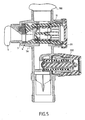
- the invention relates to a hydraulic fluid shutter comprising two closing elements sliding relative to each other.
- It relates more particularly but not limited to a security group.
- the seat is materialized by one of the faces of a fixed disc having at least one opening and on which face of the fixed disc applies the so-called shutter on both sides of a disc mobile also provided with a passage which, depending on the angular position of the movable disc with respect to the opening of the above-mentioned fixed disc, establishes or interrupts the circulation of the fluid.
- the fixed disc is immobilized in rotation while the movable disc is then guided in rotation.
- the invention proposes to remedy these drawbacks in particular.
- the invention also relates to a device for controlling the flow of a fluid equipped with said shutter.
- a shutter 1 of the type comprising two surfaces 3, 4 in contact with each other and sliding one with respect to the other.
- This shutter is associated with a hydraulic device 4 and allows to interrupt circulation between an upstream point such as a room towards a downstream point like another room.
- the operating means comprises a gripping means 7B and a means 7A for transmitting the movement exerted on the gripping means.
- At least one of the fixed elements 5 and mobile 6 is made of flexible material.
- one of the fixed or mobile elements is made of material composed mainly of rubber while the other element is hard plastic.
- Plastic material provides a smoother contact surface than that rubber.
- sealing surface we understand the surface which is positioned at look of the opening of the fixed element to prevent the circulation of fluid.
- an open cavity is positioned, either a closed cavity establishing or not establishing communication between upstream and downstream.
- the movable element is in the form of a disc and its displacement will be carried out preferably around its axis central.
- passage 5A, 6A will have the shape of a semicircle.
- the fixed element is also a disc but in particular for reasons of space, this shape will be chosen preferentially.
- the fixed element in particular when it is a disc, comprises a wedging means 10 in particular in rotation which cooperates with a fixed part of the device that houses it.
- the bead 8 will then have the shape of a ring with a bar 9 central.
- the fixed element is made of rubber and therefore the other of plastic.
- This type of shutter can therefore be integrated into fluid flow control.
- a security group was taken as a non-limiting example.
- such a safety device comprises a shut-off valve to isolate the water network from the hot water tank, a non-return valve to ensure the antipollution of the water network when the stopcock is open allowing network water to enter the balloon and a safety valve whose function is to avoid overpressure in the hot water tank.
- the stop valve of the group of security includes a shutter of the aforementioned type mounted coaxially with the non-return valve.
- the movable disc is carried by a part 7A tubular mobile in rotation in the body of the safety group, this part tubular housing itself the check valve 11 wedged in translation in said part and this tubular part has coupling means 12 in rotation with a gripping means accessible from outside the device body.
- the movable disc is immobilized in rotation on the tubular part.
- the setting in translation of the valve can be achieved by a thread or two shoulders.
- the movable disc 6 will therefore be carried by one of the ends of the part tubular 7A while the other end will present the means coupling with the gripping means.
- the tubular body 7A partially constitutes the operating means 7 of the moving disc.
- the gripping means 7B has two functions, a first being to ensure the operation of the tubular part and a second being closing the tubular body housing the shutter and the valve anti-return.
- the movable disc can advantageously be molded on the body tubular.
- This tubular body has at the level of its envelope lights 14 allowing the fluid having opened the non-return valve to be conveyed to the downstream part.
- the body of the device has a short sleeve to allow connection with the balloon and opposite this short sleeve, a second sleeve housing the safety valve.
- the fixed element is stopped in translation by the body of the group of safety on one side and by the operating axis 7A on the other. His judgment in rotation is obtained by a semi-cylindrical male form 10 which is fitted in the same female form on the body of the security group.
- the compression of the fixed element 5 between the operating axis 7A and the body is produced by means of a nut 20 (possibility of using a clips) which presses directly on the operating shaft. This compression ensures smooth, leak-free operation.
- the non-return valve is mounted in the operating axis and is held in position in a thread.
- the faces on which the pressure of the reserve 100 are in opposition and, therefore, allow to obtain a balancing of forces acting on the valve assembly 11, operating axis 7A and movable element 5, which has the consequence of providing a tap flexible to maneuver.
Landscapes
- Engineering & Computer Science (AREA)
- General Engineering & Computer Science (AREA)
- Mechanical Engineering (AREA)
- Multiple-Way Valves (AREA)
- Sliding Valves (AREA)
Abstract
Description
- un élément dit de fermeture mobile entre une position dite d'obturation où cet élément de fermeture obture le passage délimité par un siège et une position ouverte où cet élément de fermeture est écarté du siège précité et permet le passage du fluide et
- un moyen de manoeuvre de l'élément de fermeture.
- un élément fixe traversé par un passage débouchant dans une de ses faces qui constitue un siège,
- un second élément mobile pourvu également d'un passage traversant, lequel élément mobile a l'une de ses deux faces, dite face d'obturation, glissant au contact avec le siège de l'élément fixe entre une première position dite ouverte établissant la circulation du fluide au travers des passages alignés et une position de fermeture interrompant la circulation du fluide et
- un moyen de manoeuvre dudit élément mobile, cet obturateur étant caractérisé en ce qu'au moins l'un des éléments fixe et mobile est en matériau souple.
- figures 1 et 2 : des vues éclatées d'un dispositif de contrôle logeant un obturateur,
- figure 3 : le dispositif des figures 1 et 2 en coupe partielle,
- figure 4 : un groupe de sécurité,
- figure 5 : une coupe axiale de la figure 4.
- un élément 5 fixe traversé par un passage 5A débouchant dans une 2 de ses faces qui constitue un siège 2,
- un second élément 6 mobile pourvu également d'un passage 6A traversant lequel élément 6 mobile a l'une 3 de ses deux faces dite face d'obturation glissant au contact avec le siège 2 de l'élément fixe entre une première position dite ouverte établissant la circulation du fluide au travers des passages 5A, 6A alignés et une position de fermeture interrompant la circulation du fluide et
- un moyen de manoeuvre 7 dudit élément mobile.
- d'une part, un bourrelet 8 entourant à la fois la surface obturante et l'orifice par lequel transite le fluide et
- d'autre part, un second bourrelet 9 qui, s'étendant à l'intérieur de la surface délimitée par le premier bourrelet, matérialise la séparation entre la surface obturante et l'orifice.
- le joint de forme assure par son contact plan avec l'axe de manoeuvre la fonction d'étanchéité du robinet d'arrêt du groupe de sécurité,
- l'axe de manoeuvre assure la rigidité de l'ensemble robinet; il sert également de porte clapet et contribue à la transmission de l'effort du chapeau,
- l'écrou de compression assure de par son nom la parfaite application de la face avant de l'axe de manoeuvre sur la face plan du joint de forme; cette compression permet d'assurer un fonctionnement sans fuite et doux,
- le clapet de non retour assure la fonction d'anti-pollution; il est complètement intégré au niveau de l'axe de manoeuvre afin d'obtenir un ensemble compact et rigide,
- le chapeau, d'une part, sert de préhension pour manoeuvrer le robinet et assure la transmission du couple de manoeuvre de l'axe, sa conception permettant d'utiliser par exemple un tournevis pour le manoeuvre à distance et, d'autre part, permet de contrôler aisément le clapet par le fait qu'il est encliqueté sur l'axe.
Claims (9)
- Obturateur de fluide hydraulique comprenant :cet obturateur étant CARACTERISE en ce qu'au moins l'un des éléments fixe (5) et mobile (6) est en matériau souple.un élément (5) fixe traversé par un passage (5A) débouchant dans une (2) de ses faces qui constitue un siège (2),un second élément (6) mobile pourvu également d'un passage (6A) traversant, lequel élément (6) mobile a l'une (3) de ses deux faces dite face d'obturation glissant au contact avec le siège (2) de l'élément fixe entre une première position dite ouverte établissant la circulation du fluide au travers des passages (5A, 6A) alignés et une position de fermeture interrompant la circulation du fluide etun moyen de manoeuvre (7) dudit élément mobile,
- Obturateur selon la revendication 1 caractérisé en ce que l'un des éléments fixe ou mobile est en matériau composé principalement de caoutchouc tandis que l'autre élément est en plastique dur.
- Obturateur selon la revendication 1 ou 2 caractérisé en ce que l'une des deux faces en contact l'une de l'autre est une face plane tandis que l'autre face présente en saillied'une part, un bourrelet (8) entourant à la fois la surface obturante et l'orifice par lequel transite le fluide etd'autre part, un second bourrelet (9) qui, s'étendant à l'intérieur de la surface délimitée par le premier bourrelet, matérialise la séparation entre la surface obturante et l'orifice.
- Obturateur selon la revendication 3 caractérisé en ce que l'élément mobile présente les bourrelets (8, 9).
- Obturateur selon la revendication 1 caractérisé en ce que l'élément mobile se présente sous la forme d'un disque et son déplacement est réalisé autour de son axe central.
- Obturateur selon la revendication 5 caractérisé en ce que l'élément (5) fixe est un disque et la face opposée à celle (2) constituant le siège de cet élément fixe présente un moyen (10) de calage en rotation.
- Dispositif de contrôle de l'écoulement d'un fluide caractérisé en ce qu'il est équipé d'un obturateur selon l'une quelconque des revendications 1 à 6.
- Dispositif de contrôle selon la revendication 7 caractérisé en ce que le dispositif est un groupe de sécurité disposé entre l'alimentation (S) en eau et une réserve (100) comprenant donc, selon le sens de circulation du réseau d'eau, un robinet d'arrêt permettant d'isoler le réseau d'eau de l'aval, un clapet anti-retour pour assurer l'anti-pollution du réseau d'eau et une soupape (200) de sécurité.
- Dispositif de contrôle selon la revendication 8 caractérisé en ce que :l'obturateur formé des éléments fixe et mobile est monté coaxialement au clapet anti-retour et,le disque mobile est porté par une pièce (7A) tubulaire mobile en rotation dans le corps du groupe de sécurité, cette pièce tubulaire logeant elle-même le clapet (11) anti-retour calé en translation dans la dite pièce et cette pièce tubulaire présente des moyens d'accouplement (12) en rotation avec un moyen de préhension accessible depuis l'extérieur du corps du dispositif, la dite pièce tubulaire constituant partiellement le moyen de manoeuvre de l'élément mobile.
Applications Claiming Priority (2)
| Application Number | Priority Date | Filing Date | Title |
|---|---|---|---|
| FR0005125A FR2808069A1 (fr) | 2000-04-20 | 2000-04-20 | Obturation de fluide hydraulique et dispositif de controle de l'ecoulement d'un fluide equipe dudit obturateur |
| FR0005125 | 2000-04-20 |
Publications (1)
| Publication Number | Publication Date |
|---|---|
| EP1148280A1 true EP1148280A1 (fr) | 2001-10-24 |
Family
ID=8849474
Family Applications (1)
| Application Number | Title | Priority Date | Filing Date |
|---|---|---|---|
| EP01490013A Withdrawn EP1148280A1 (fr) | 2000-04-20 | 2001-04-19 | Vanne à tiroir |
Country Status (2)
| Country | Link |
|---|---|
| EP (1) | EP1148280A1 (fr) |
| FR (1) | FR2808069A1 (fr) |
Citations (4)
| Publication number | Priority date | Publication date | Assignee | Title |
|---|---|---|---|---|
| US4331176A (en) * | 1980-03-03 | 1982-05-25 | American Standard Inc. | Replaceable cartridge valve assembly |
| US5435348A (en) * | 1992-10-30 | 1995-07-25 | Ntn Corporation | Valve assembly |
| US5623965A (en) * | 1995-10-30 | 1997-04-29 | Delco Electronics Corporation | Low effort vacuum valve assembly with rotary actuator |
| WO1998014728A1 (fr) * | 1996-10-01 | 1998-04-09 | Masco Corporation Of Indiana | Bouchon male a garnitures de retenue assujetties pour cartouche de robinet de puisage d'eau |
-
2000
- 2000-04-20 FR FR0005125A patent/FR2808069A1/fr active Pending
-
2001
- 2001-04-19 EP EP01490013A patent/EP1148280A1/fr not_active Withdrawn
Patent Citations (4)
| Publication number | Priority date | Publication date | Assignee | Title |
|---|---|---|---|---|
| US4331176A (en) * | 1980-03-03 | 1982-05-25 | American Standard Inc. | Replaceable cartridge valve assembly |
| US5435348A (en) * | 1992-10-30 | 1995-07-25 | Ntn Corporation | Valve assembly |
| US5623965A (en) * | 1995-10-30 | 1997-04-29 | Delco Electronics Corporation | Low effort vacuum valve assembly with rotary actuator |
| WO1998014728A1 (fr) * | 1996-10-01 | 1998-04-09 | Masco Corporation Of Indiana | Bouchon male a garnitures de retenue assujetties pour cartouche de robinet de puisage d'eau |
Also Published As
| Publication number | Publication date |
|---|---|
| FR2808069A1 (fr) | 2001-10-26 |
Similar Documents
| Publication | Publication Date | Title |
|---|---|---|
| US5819791A (en) | Check valve including means to permit selective back flow | |
| KR100905068B1 (ko) | 수동전환밸브 | |
| EP2021664B1 (fr) | Robinet | |
| FR2504970A1 (fr) | Appareil de raccordement pour tete de puits de petrole | |
| FR2797190A1 (fr) | Robinet a pincement pour instruments et appareils medicaux | |
| FR2865259A1 (fr) | Raccord rapide et procede de desacouplement des elements male et femelle d'un tel raccord | |
| FR2559234A1 (fr) | Dispositif d'actionnement de vanne a moteur | |
| EP0805278B1 (fr) | Dispositif de vérin pneumatique | |
| FR2792988A1 (fr) | Cartouche de robinet mitigeur a limitation de temperature | |
| US11828416B2 (en) | Gas cylinder valve with radially extending operating handle | |
| FR2825282A1 (fr) | Robinet d'arret pour endoscope avec element d'arret | |
| TW201840449A (zh) | 液壓自行車組件控制裝置 | |
| FR2608722A1 (fr) | Robinet de soutirage de produit liquide, a commande manuelle, admission d'air et fermeture automatique pour reservoirs divers | |
| EP1468147B1 (fr) | Tuyau de douche ayant une vanne a deux voies, et vanne a deux voies pour un tuyau de douche | |
| FR2808069A1 (fr) | Obturation de fluide hydraulique et dispositif de controle de l'ecoulement d'un fluide equipe dudit obturateur | |
| EP0611219B1 (fr) | Soupapes de sûreté à membrane du type cartouche, de conception modulaire | |
| WO2017202958A1 (fr) | Embout de récipient de liquide destiné à s'adapter sur un embout de réservoir | |
| EP0985111B1 (fr) | Mecanisme mitigeur pour armature sanitaire | |
| EP0985112B1 (fr) | Mecanisme mitigeur pour armature sanitaire | |
| FR2797932A1 (fr) | Vanne manuelle | |
| FR2762661A1 (fr) | Manchon d'accouplement pour un accouplement hydraulique | |
| EP0098621B1 (fr) | Robinet mélangeur d'eau chaude et d'eau froide | |
| FR2869088A1 (fr) | Raccord femelle pour conduite de fluide | |
| FR2866409A3 (fr) | Raccord femelle pour conduite de fluide | |
| FR2735837A1 (fr) | Clapet anti-retour a levee automatique et raccord muni d'un tel clapet |
Legal Events
| Date | Code | Title | Description |
|---|---|---|---|
| PUAI | Public reference made under article 153(3) epc to a published international application that has entered the european phase |
Free format text: ORIGINAL CODE: 0009012 |
|
| AK | Designated contracting states |
Kind code of ref document: A1 Designated state(s): AT BE CH CY DE DK ES FI FR GB GR IE IT LI LU MC NL PT SE TR |
|
| AX | Request for extension of the european patent |
Free format text: AL;LT;LV;MK;RO;SI |
|
| 17P | Request for examination filed |
Effective date: 20011027 |
|
| AKX | Designation fees paid |
Free format text: AT BE CH CY DE DK ES FI FR GB GR IE IT LI LU MC NL PT SE TR |
|
| 17Q | First examination report despatched |
Effective date: 20031103 |
|
| STAA | Information on the status of an ep patent application or granted ep patent |
Free format text: STATUS: THE APPLICATION IS DEEMED TO BE WITHDRAWN |
|
| 18D | Application deemed to be withdrawn |
Effective date: 20031031 |