EP1148311A2 - Procédé de cuisson d'un matériau contenant des carbonates - Google Patents
Procédé de cuisson d'un matériau contenant des carbonates Download PDFInfo
- Publication number
- EP1148311A2 EP1148311A2 EP01810263A EP01810263A EP1148311A2 EP 1148311 A2 EP1148311 A2 EP 1148311A2 EP 01810263 A EP01810263 A EP 01810263A EP 01810263 A EP01810263 A EP 01810263A EP 1148311 A2 EP1148311 A2 EP 1148311A2
- Authority
- EP
- European Patent Office
- Prior art keywords
- shaft
- fuel
- firing
- lances
- combustion
- Prior art date
- Legal status (The legal status is an assumption and is not a legal conclusion. Google has not performed a legal analysis and makes no representation as to the accuracy of the status listed.)
- Granted
Links
Images


Classifications
-
- F—MECHANICAL ENGINEERING; LIGHTING; HEATING; WEAPONS; BLASTING
- F23—COMBUSTION APPARATUS; COMBUSTION PROCESSES
- F23B—METHODS OR APPARATUS FOR COMBUSTION USING ONLY SOLID FUEL
- F23B1/00—Combustion apparatus using only lump fuel
- F23B1/30—Combustion apparatus using only lump fuel characterised by the form of combustion chamber
- F23B1/36—Combustion apparatus using only lump fuel characterised by the form of combustion chamber shaft-type
-
- F—MECHANICAL ENGINEERING; LIGHTING; HEATING; WEAPONS; BLASTING
- F23—COMBUSTION APPARATUS; COMBUSTION PROCESSES
- F23G—CREMATION FURNACES; CONSUMING WASTE PRODUCTS BY COMBUSTION
- F23G5/00—Incineration of waste; Incinerator constructions; Details, accessories or control therefor
- F23G5/24—Incineration of waste; Incinerator constructions; Details, accessories or control therefor having a vertical, substantially cylindrical, combustion chamber
Definitions
- the invention relates to a method for burning carbonate Material in a shaft furnace, with gravity delivery through a preheating zone, at least one firing zone and a cooling zone to a discharge device, one Fuel supply in the combustion zone or adjacent to it over several firing lances guided through the shaft wall and combustion air supplied as cooling air under positive pressure becomes.
- An energy-saving mode of operation is through multi-shaft stoves according to the direct current regenerative process in so-called MARCH oven given. At them the fuel gets through hanging lances immersed in the firing material fed that evenly over the in the loading zone Shaft cross section are arranged distributed. Such stoves are more well known However, versions are only suitable for soft fire.
- US-A-4,094,629 proposed the width of the Shaft cross-section due to its ring-shaped design reduce and additional in the existing inner wall To arrange burner outlets. In this way, one steady downward movement of the fuel under Gravity can be maintained without the material flow is disturbed by internals in the shaft.
- the invention has for its object a method of to find the type mentioned above, by the particular small-grain fuel with different degrees of firing up to dead fire in an economical way in shaft furnaces burned into a high quality product can.
- each burner lance is preferably only used to generate each a flame is provided, it has compared to numerous burner supports with a small burner Cross section and therefore only leads to an insignificant Influencing the fuel flow. It has been surprising demonstrated that the firing lances are still adequate Flexural strength to withstand the pressure of the fluid flowing around them granular fuel. Preferentially will but the grain size of the fuel is limited to 70 mm.
- each firing lance perpendicular to the The shaft wall is prevented from getting between it and the The shaft wall forms a gap in which fuel accumulates could.
- the local restriction of the shaft cross-section through the lances projecting into it decrease by the firing lances in several levels one above the other and to those of another plane in the circumferential direction staggered so that the required Fuel quantity distributed over several shaft levels is fed.
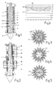
- the shaft furnace 1 shown in longitudinal section in FIG. 1 is aligned vertically and at least has the process technology significant area of its length a chess room 2 with constant cross section. This can be different e.g. circular, elliptical or polygonal his.
- the cross section is circular, with an outer wall 3 made of steel, due to the required high process temperatures on the inside at least one brick, refractory lining layer 4 wearing.
- the height of the furnace shaft 2 is due to the process in connection with the setting of the conveying speed dwell times to be determined by means of the discharge device 5 of the fuel is determined. These dwell times distribute themselves on an upper, to the loading area 6 subsequent preheating zone 7, down to one following firing zone 8 and one up to the discharge device 5 running cooling zone 9.
- the supply of gaseous, liquid or powder Fuel takes place over numerous, in one or more levels 10 to 12 arranged firing lances 13, which are characterized by the Shaft wall 3, 4 extend into shaft space 2.
- the temperatures would be in the Proximity of the shaft wall too high, with the risk of sintering together and in the middle of the shaft too low and below the minimum firing temperature indicated by curve 17.
- the radial positions that can be read on the abscissa of the diagram are only relative and not to a specific one Related shaft diameter.
- the shaft diameter can, however correspond to a radius of 1, although larger ones Shaft dimensions can be realized, e.g. with a Diameter of three or more meters.
- the fuel tube 18 has a connecting piece 22 for the feed line primary combustion air. It is also at the rear End of the firing lance 13 coaxially with this Fuel pipe 23, 24 or 25 used, depending on the type of fuel to be used is executed. For powdered fuel, the fuel pipe the shape of a short nozzle 23 accordingly Fig. 7. For liquid and gaseous fuel stretches the fuel pipe 24 or 25 until just before the mouth 14 of the firing lance 13 to be there with the in the enclosing Ring channel 26 incoming primary combustion air mix.
- 3 to 5 illustrate a different angular arrangement the firing lances 13 arranged in three planes, so the firing lances 13 to those of another level are angularly offset.
- the focal lances 13 of the different focal planes 10, 11 and 12 is a special one even with small flames extensive coverage of the shaft cross section the flames formed at each of the mouths 14.
- the size of these flames is due to several factors determined, i.e. the amount of fuel, the amount of primary and secondary combustion air as well as the grain size of the fuel. A small grain size leads to a denser bulk packing and thus a smaller one Spread of the flame.
- the limitation of Grain size to an area with preferably less than 70 mm grain size the advantage of a lower mechanical load that protrudes transversely into the flowing bulk material Firing lances 13 and the advantage of a smaller adjustable Dwell time, so that sintering together of fuel can be prevented by a short dwell time.
- grain size should be the grain size distribution are in the smallest possible area.
- the firing lance in question be held in the manner of a weighing beam, with a Force measuring point outside the shaft wall 3 and with one Device for generating mechanical vibrations that Exceeding a permissible force automatically switched on becomes. In this way, the firing lance can be shake it free if a material jam should form on it. Shaking the firing lance can also push it into lighten the chess room 2.
- the fuel supply in the individual focal planes 10, 11 and 12 can be regulated individually to zero depending on of the desired degree of firing or the residence time in a certain temperature range a certain temperature range in the longitudinal direction of the shaft or in the direction of flow of the air flowing in from below.
- This air is in the range of e.g. designed as a drawer Discharge device 5 with overpressure by at least fed a blower, not shown, so that they in Countercurrent to that moving downward by gravity Bulk of bulk goods through its grain structure upwards flows. It first serves as cooling air in the cooling zone 9, then in the firing zone 8 as e.g. secondary Combustion air and finally, in the upper preheating zone 7 of the furnace to preheat the firing material and thereby, accordingly a preferred embodiment of the invention for Preheating the primary flowing to the firing lances 13 Combustion air in heat exchange pipes arranged there 29.
- the arrangement of the firing lances 13 or of their mouths 14, distributed over the shaft cross section, enables new types of process management, with particular high flame temperatures in the range of 1800 ° C with short Dwell time without one at such temperatures expected sintering together i.e. the formation of blocks occurs, so that a previously not possible Hard burning in a vertical shaft furnace with gaseous, liquid and powdered fuels is possible.
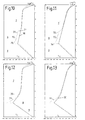
- FIGs of Figures 10 to 13 show for a particular one Dwell time due to the control of the fuel supply in connection with adapted primary air supply via the lances 13 and secondary supplied in countercurrent Combustion air realizable temperature profiles for the lime fuel (CaCO3), based on the longitudinal section of the shaft furnace.
- the temperature of the fuel represented by a solid line 30 while the temperature of the combustion Fuel gas and the cooling or secondary combustion air dashed line 31 corresponds.
- the fuel supply is graded via the three Focal planes 10 to 12 arranged focal lances 13 in essential less amount than for hard fire, so that flame temperatures corresponding to the three temperature peaks 32 train up to 34. at about 1200 ° C in the first focal plane and are around 1400 ° C in the third focal plane.
- the fuel flowing from top to bottom thus arrives in the first focal plane 30 first in contact with fuel gas of 1200 ° Celsius and in the subsequent focal planes with hotter fuel gas of a maximum of approx.
- This heating takes place inside the furnace 1 'by the combustion air is passed through heat exchange tubes 36, which with a Zuund Return line part 37.38 hanging vertically and in the circumferential direction of the shaft 2 or evenly on the shaft cross-section distributed in the fuel of the preheating zone 7 immerse.
- the arrangement of the heat exchange tubes 36 in the furnace 1 'in direct contact with the fuel and the fuel gases leads to a particularly good heat transfer through heat conduction, Convection and heat radiation.
- the heat exchange surfaces of the tubes 36 through the Gravitational influence of fuel flowing along them cleaned automatically.
- FIGS 11 and 13 illustrate that due to the additional Heat exchanges in the tubes 36 result in other types Temperature curve in the direction of the shaft.
- the double shaft furnaces 40, 40 'and 40 "of the exemplary embodiments the invention according to Fig.14 to Fig.16 are like that known MAERZ oven operated by the regenerative process.
- the double shaft furnace according to Fig. 15 is in both shafts 41,42 only transverse lances 55 are provided.
- the Double shaft furnace according to Fig.16 has in contrast in addition Pre-heating area 56 hanging heat exchange tubes 58 for heating primary combustion air, as before for Shaft furnace according to Fig.2 has been described.
Landscapes
- Engineering & Computer Science (AREA)
- Mechanical Engineering (AREA)
- General Engineering & Computer Science (AREA)
- Chemical & Material Sciences (AREA)
- Combustion & Propulsion (AREA)
- Thermal Sciences (AREA)
- Physics & Mathematics (AREA)
- Vertical, Hearth, Or Arc Furnaces (AREA)
- Feeding, Discharge, Calcimining, Fusing, And Gas-Generation Devices (AREA)
- Muffle Furnaces And Rotary Kilns (AREA)
- Furnace Details (AREA)
- Ceramic Products (AREA)
- Carbon And Carbon Compounds (AREA)
- Crucibles And Fluidized-Bed Furnaces (AREA)
- Bakery Products And Manufacturing Methods Therefor (AREA)
- Processing Of Solid Wastes (AREA)
- Compounds Of Alkaline-Earth Elements, Aluminum Or Rare-Earth Metals (AREA)
Applications Claiming Priority (2)
| Application Number | Priority Date | Filing Date | Title |
|---|---|---|---|
| CH7212000 | 2000-04-11 | ||
| CH7212000 | 2000-04-11 |
Publications (3)
| Publication Number | Publication Date |
|---|---|
| EP1148311A2 true EP1148311A2 (fr) | 2001-10-24 |
| EP1148311A3 EP1148311A3 (fr) | 2003-12-03 |
| EP1148311B1 EP1148311B1 (fr) | 2005-11-09 |
Family
ID=4531564
Family Applications (1)
| Application Number | Title | Priority Date | Filing Date |
|---|---|---|---|
| EP01810263A Expired - Lifetime EP1148311B1 (fr) | 2000-04-11 | 2001-03-16 | Procédé de cuisson d'un matériau contenant des carbonates |
Country Status (11)
| Country | Link |
|---|---|
| US (1) | US6461154B2 (fr) |
| EP (1) | EP1148311B1 (fr) |
| CN (1) | CN100414234C (fr) |
| AT (1) | ATE309514T1 (fr) |
| BR (1) | BR0101435B1 (fr) |
| DE (1) | DE50107945D1 (fr) |
| EA (1) | EA003894B1 (fr) |
| ES (1) | ES2254352T3 (fr) |
| IL (1) | IL142368A (fr) |
| MX (1) | MXPA01003608A (fr) |
| UA (1) | UA72224C2 (fr) |
Cited By (2)
| Publication number | Priority date | Publication date | Assignee | Title |
|---|---|---|---|---|
| WO2020182584A1 (fr) * | 2019-03-08 | 2020-09-17 | Maerz Ofenbau Ag | Procédé et four à cuve pour la combustion de matières contenant du carbone dans un four à cuve |
| BE1027100A1 (de) | 2019-03-08 | 2020-09-30 | Maerz Ofenbau | Verfahren und Schachtofen zum Brennen von karbonhaltigem Material in einem Schachtofen |
Families Citing this family (11)
| Publication number | Priority date | Publication date | Assignee | Title |
|---|---|---|---|---|
| EP1656443A4 (fr) * | 2003-05-02 | 2007-06-06 | Sigma Aldrich Co | Lyse cellulaire a phase solide et plaque de saisie |
| WO2006026248A1 (fr) | 2004-08-25 | 2006-03-09 | Sigma-Aldrich Co. | Compositions et procedes faisant appel a des combinaisons de detergents zwitterioniques |
| WO2008070931A1 (fr) * | 2006-12-15 | 2008-06-19 | Eestech, Inc. | Appareil de combustion |
| BE1018212A3 (fr) * | 2008-07-10 | 2010-07-06 | Carmeuse Res And Technology | Methode de conduite des fours droits de type regeneratif pour la production de chaux. |
| DE102009058304B4 (de) * | 2009-12-15 | 2013-01-17 | Maerz Ofenbau Ag | Gleichstrom-Gegenstrom-Regenerativ-Kalkofen sowie Verfahren zum Betreiben desselben |
| US20130052600A1 (en) * | 2010-03-17 | 2013-02-28 | Cimprogetti S.P.A. | Kiln for the production of calcium oxide |
| CN102052826A (zh) * | 2010-12-23 | 2011-05-11 | 马全才 | 节能型竖窑 |
| DE102016103937A1 (de) | 2016-03-04 | 2017-09-07 | Maerz Ofenbau Ag | Ofen und Verfahren zum Betreiben eines Ofens |
| PT3604920T (pt) * | 2017-03-24 | 2021-07-23 | Af Ingenieria S L | Unidade de tratamento de resíduos |
| SE540217C2 (en) * | 2017-06-26 | 2018-05-02 | Faeltkalk Ab | A vertical lime kiln |
| CN114111346B (zh) * | 2021-11-30 | 2023-12-01 | 广东韶钢松山股份有限公司 | 一种双膛窑检修后兑火提温快速复产方法 |
Family Cites Families (11)
| Publication number | Priority date | Publication date | Assignee | Title |
|---|---|---|---|---|
| US3355158A (en) * | 1966-04-26 | 1967-11-28 | Harbison Walker Refractories | Shaft kiln |
| US3887326A (en) * | 1971-02-08 | 1975-06-03 | Ici Ltd | Kilns and furnaces |
| DE2705710C3 (de) * | 1977-02-11 | 1980-06-04 | Kloeckner-Humboldt-Deutz Ag, 5000 Koeln | Gegenstrombrennverfahren zur Erzeugung von Branntkalk und Schachtofen zur Durchfuhrung des Verfahrens |
| CH638604A5 (de) * | 1978-12-29 | 1983-09-30 | Maerz Ofenbau | Verfahren zum brennen von mineralischen karbonathaltigen rohstoffen im gleichstrom-regenerativ-schachthofen. |
| CH647313A5 (de) * | 1980-04-30 | 1985-01-15 | Maerz Ofenbau | Regenerativ-schachtofen zum brennen von karbonathaltigen rohstoffen. |
| AT377248B (de) * | 1982-07-12 | 1985-02-25 | Maerz Ofenbau | Verfahren und schachtofen zum brennen von kalkstein |
| AT378970B (de) * | 1982-12-21 | 1985-10-25 | Voest Alpine Ag | Verfahren und vorrichtung zur herstellung von flùssigem roheisen oder stahlvorprodukten |
| US4747773A (en) * | 1986-03-21 | 1988-05-31 | Predescu Lucian A | Shaft kiln utilized for lime production |
| DE4090997T1 (de) * | 1989-06-10 | 1991-08-29 | September 27 Research Inst | Ofen fuer die kalziumkarbidherstellung nach dem sauerstoffwaermeverfahren |
| CH686459A5 (de) * | 1992-03-07 | 1996-03-29 | Maerz Ofenbau | Schachtofen zum Brennen von stuckigem, mineralischem Fuellgut. |
| GB9604475D0 (en) * | 1996-03-01 | 1996-05-01 | Boc Group Plc | Furnace waste gas combustion control |
-
2001
- 2001-03-16 EP EP01810263A patent/EP1148311B1/fr not_active Expired - Lifetime
- 2001-03-16 AT AT01810263T patent/ATE309514T1/de active
- 2001-03-16 ES ES01810263T patent/ES2254352T3/es not_active Expired - Lifetime
- 2001-03-16 DE DE50107945T patent/DE50107945D1/de not_active Expired - Lifetime
- 2001-03-29 UA UA2001032083A patent/UA72224C2/uk unknown
- 2001-04-02 IL IL14236801A patent/IL142368A/en active IP Right Grant
- 2001-04-06 US US09/827,464 patent/US6461154B2/en not_active Expired - Lifetime
- 2001-04-09 MX MXPA01003608A patent/MXPA01003608A/es active IP Right Grant
- 2001-04-10 CN CNB011163631A patent/CN100414234C/zh not_active Expired - Lifetime
- 2001-04-10 BR BRPI0101435-8A patent/BR0101435B1/pt not_active IP Right Cessation
- 2001-04-11 EA EA200100339A patent/EA003894B1/ru not_active IP Right Cessation
Cited By (4)
| Publication number | Priority date | Publication date | Assignee | Title |
|---|---|---|---|---|
| WO2020182584A1 (fr) * | 2019-03-08 | 2020-09-17 | Maerz Ofenbau Ag | Procédé et four à cuve pour la combustion de matières contenant du carbone dans un four à cuve |
| BE1027100A1 (de) | 2019-03-08 | 2020-09-30 | Maerz Ofenbau | Verfahren und Schachtofen zum Brennen von karbonhaltigem Material in einem Schachtofen |
| BE1027100B1 (de) * | 2019-03-08 | 2020-10-05 | Maerz Ofenbau | Verfahren und Schachtofen zum Brennen von karbonhaltigem Material in einem Schachtofen |
| US11703280B2 (en) | 2019-03-08 | 2023-07-18 | Maerz Ofenbau Ag | Method and shaft furnace for burning carbon-containing material in a shaft furnace |
Also Published As
| Publication number | Publication date |
|---|---|
| IL142368A0 (en) | 2002-03-10 |
| EP1148311A3 (fr) | 2003-12-03 |
| EA200100339A3 (ru) | 2002-02-28 |
| CN100414234C (zh) | 2008-08-27 |
| MXPA01003608A (es) | 2005-06-30 |
| EP1148311B1 (fr) | 2005-11-09 |
| BR0101435B1 (pt) | 2010-11-16 |
| ATE309514T1 (de) | 2005-11-15 |
| US20010029005A1 (en) | 2001-10-11 |
| BR0101435A (pt) | 2001-11-13 |
| CN1317679A (zh) | 2001-10-17 |
| DE50107945D1 (de) | 2005-12-15 |
| UA72224C2 (uk) | 2005-02-15 |
| EA200100339A2 (ru) | 2001-10-22 |
| IL142368A (en) | 2004-02-19 |
| EA003894B1 (ru) | 2003-10-30 |
| US6461154B2 (en) | 2002-10-08 |
| ES2254352T3 (es) | 2006-06-16 |
Similar Documents
| Publication | Publication Date | Title |
|---|---|---|
| DE2808213C2 (de) | Rekuperativkoksofen sowie Verfahren zum Betreiben desselben | |
| EP1148311B1 (fr) | Procédé de cuisson d'un matériau contenant des carbonates | |
| EP0854339B1 (fr) | Procédé et installation pour le traitement thermique de charges finement granulées | |
| EP0003123A1 (fr) | Procédé et dispositif pour précalciner des matières premières carbonées | |
| CH686459A5 (de) | Schachtofen zum Brennen von stuckigem, mineralischem Fuellgut. | |
| DE2324565A1 (de) | Verfahren und anlage zur waermebehandlung von feinkoernigem gut | |
| DE2558506A1 (de) | Verfahren zur thermischen behandlung von staubfoermigem gut, insbesondere zum brennen von zement in mehreren stufen | |
| DE3781987T2 (de) | Ofen. | |
| EP1634026B1 (fr) | Procede de combustion de matieres en morceaux au moyen d'un gaz pauvre | |
| DE1771990B2 (de) | Verfahren und Vorrichtung zum Schmelzen eines Rohglasgemenges | |
| CH638296A5 (de) | Verfahren und anlage zum brennen von karbonhaltigen rohstoffen mittels zerkleinerten festen brennstoffen in einem gleichstrom-regenerativ-schachtofen. | |
| DE1063579B (de) | Wirbelschichtanlage mit kontinuierlichem Durchfluss der Feststoffe | |
| DE2826167B1 (de) | Verfahren zum Brennen von stueckigem Brenngut sowie Ringschachtofen zu dessen Durchfuehrung | |
| DE2534438B2 (de) | Verfahren und Vorrichtung zum Brennen von pulverförmigem Zementrohmehl | |
| EP3935332B1 (fr) | Procédé et four à cuve pour la combustion de matières contenant du carbone dans un four à cuve | |
| WO1981002747A1 (fr) | Procede et dispositif pour l'allumage d'un melange de frittage | |
| DE3131200C2 (de) | Metallheizofen | |
| DE2225782A1 (de) | Verfahren zum Brennen von Kalk | |
| EP3423769B1 (fr) | Four et procédé permettant de faire fonctionner un four | |
| AT390248B (de) | Verfahren und vorrichtung zum brennen von karbonathaltigem, mineralischem brenngut | |
| DE1157133B (de) | Verfahren zum Brennen und Kuehlen von koernigem Gut, z.B. von Kalkstein im Schachtofen, und Ofen zur Ausuebung des Verfahrens | |
| DE102006039204A1 (de) | Ringschachtofen | |
| DE2517552A1 (de) | Verfahren zur thermischen behandlung von feinkoernigem gut, insbesondere zum brennen von zement | |
| DE3614177C2 (de) | Brennkammer | |
| DE2000766A1 (de) | Verfahren zum Betrieb eines regenerativen Winderhitzers und Erhitzer zur Durchfuehrung dieses Verfahrens |
Legal Events
| Date | Code | Title | Description |
|---|---|---|---|
| PUAI | Public reference made under article 153(3) epc to a published international application that has entered the european phase |
Free format text: ORIGINAL CODE: 0009012 |
|
| AK | Designated contracting states |
Kind code of ref document: A2 Designated state(s): AT BE CH CY DE DK ES FI FR GB GR IE IT LI LU MC NL PT SE TR |
|
| AX | Request for extension of the european patent |
Free format text: AL;LT;LV;MK;RO;SI |
|
| PUAL | Search report despatched |
Free format text: ORIGINAL CODE: 0009013 |
|
| RIC1 | Information provided on ipc code assigned before grant |
Ipc: 7F 27B 1/04 B Ipc: 7F 27B 1/08 B Ipc: 7F 27B 1/00 A Ipc: 7C 04B 2/12 B Ipc: 7F 27B 1/10 B |
|
| AK | Designated contracting states |
Kind code of ref document: A3 Designated state(s): AT BE CH CY DE DK ES FI FR GB GR IE IT LI LU MC NL PT SE TR |
|
| AX | Request for extension of the european patent |
Extension state: AL LT LV MK RO SI |
|
| 17P | Request for examination filed |
Effective date: 20040603 |
|
| AKX | Designation fees paid |
Designated state(s): AT BE CH CY DE DK ES FI FR GB GR IE IT LI LU MC NL PT SE TR |
|
| GRAP | Despatch of communication of intention to grant a patent |
Free format text: ORIGINAL CODE: EPIDOSNIGR1 |
|
| GRAS | Grant fee paid |
Free format text: ORIGINAL CODE: EPIDOSNIGR3 |
|
| GRAA | (expected) grant |
Free format text: ORIGINAL CODE: 0009210 |
|
| AK | Designated contracting states |
Kind code of ref document: B1 Designated state(s): AT BE CH CY DE DK ES FI FR GB GR IE IT LI LU MC NL PT SE TR |
|
| PG25 | Lapsed in a contracting state [announced via postgrant information from national office to epo] |
Ref country code: FI Free format text: LAPSE BECAUSE OF FAILURE TO SUBMIT A TRANSLATION OF THE DESCRIPTION OR TO PAY THE FEE WITHIN THE PRESCRIBED TIME-LIMIT Effective date: 20051109 |
|
| REG | Reference to a national code |
Ref country code: GB Ref legal event code: FG4D Free format text: NOT ENGLISH |
|
| REG | Reference to a national code |
Ref country code: CH Ref legal event code: EP |
|
| REG | Reference to a national code |
Ref country code: IE Ref legal event code: FG4D Free format text: LANGUAGE OF EP DOCUMENT: GERMAN |
|
| REF | Corresponds to: |
Ref document number: 50107945 Country of ref document: DE Date of ref document: 20051215 Kind code of ref document: P |
|
| PG25 | Lapsed in a contracting state [announced via postgrant information from national office to epo] |
Ref country code: GR Free format text: LAPSE BECAUSE OF FAILURE TO SUBMIT A TRANSLATION OF THE DESCRIPTION OR TO PAY THE FEE WITHIN THE PRESCRIBED TIME-LIMIT Effective date: 20060209 Ref country code: DK Free format text: LAPSE BECAUSE OF FAILURE TO SUBMIT A TRANSLATION OF THE DESCRIPTION OR TO PAY THE FEE WITHIN THE PRESCRIBED TIME-LIMIT Effective date: 20060209 |
|
| REG | Reference to a national code |
Ref country code: SE Ref legal event code: TRGR |
|
| GBT | Gb: translation of ep patent filed (gb section 77(6)(a)/1977) |
Effective date: 20060130 |
|
| PG25 | Lapsed in a contracting state [announced via postgrant information from national office to epo] |
Ref country code: LU Free format text: LAPSE BECAUSE OF NON-PAYMENT OF DUE FEES Effective date: 20060331 Ref country code: MC Free format text: LAPSE BECAUSE OF NON-PAYMENT OF DUE FEES Effective date: 20060331 |
|
| PG25 | Lapsed in a contracting state [announced via postgrant information from national office to epo] |
Ref country code: PT Free format text: LAPSE BECAUSE OF FAILURE TO SUBMIT A TRANSLATION OF THE DESCRIPTION OR TO PAY THE FEE WITHIN THE PRESCRIBED TIME-LIMIT Effective date: 20060410 |
|
| REG | Reference to a national code |
Ref country code: ES Ref legal event code: FG2A Ref document number: 2254352 Country of ref document: ES Kind code of ref document: T3 |
|
| ET | Fr: translation filed | ||
| PLBE | No opposition filed within time limit |
Free format text: ORIGINAL CODE: 0009261 |
|
| STAA | Information on the status of an ep patent application or granted ep patent |
Free format text: STATUS: NO OPPOSITION FILED WITHIN TIME LIMIT |
|
| 26N | No opposition filed |
Effective date: 20060810 |
|
| PG25 | Lapsed in a contracting state [announced via postgrant information from national office to epo] |
Ref country code: CY Free format text: LAPSE BECAUSE OF FAILURE TO SUBMIT A TRANSLATION OF THE DESCRIPTION OR TO PAY THE FEE WITHIN THE PRESCRIBED TIME-LIMIT Effective date: 20051109 |
|
| REG | Reference to a national code |
Ref country code: CH Ref legal event code: NV Representative=s name: DIPL.-ING. HORST QUEHL PATENTANWALT |
|
| REG | Reference to a national code |
Ref country code: FR Ref legal event code: PLFP Year of fee payment: 16 |
|
| REG | Reference to a national code |
Ref country code: FR Ref legal event code: PLFP Year of fee payment: 17 |
|
| REG | Reference to a national code |
Ref country code: FR Ref legal event code: PLFP Year of fee payment: 18 |
|
| PGFP | Annual fee paid to national office [announced via postgrant information from national office to epo] |
Ref country code: AT Payment date: 20200320 Year of fee payment: 20 Ref country code: DE Payment date: 20200320 Year of fee payment: 20 Ref country code: IE Payment date: 20200320 Year of fee payment: 20 Ref country code: NL Payment date: 20200319 Year of fee payment: 20 Ref country code: GB Payment date: 20200323 Year of fee payment: 20 Ref country code: SE Payment date: 20200323 Year of fee payment: 20 |
|
| PGFP | Annual fee paid to national office [announced via postgrant information from national office to epo] |
Ref country code: CH Payment date: 20200319 Year of fee payment: 20 Ref country code: BE Payment date: 20200319 Year of fee payment: 20 |
|
| PGFP | Annual fee paid to national office [announced via postgrant information from national office to epo] |
Ref country code: FR Payment date: 20200319 Year of fee payment: 20 Ref country code: TR Payment date: 20200316 Year of fee payment: 20 |
|
| PGFP | Annual fee paid to national office [announced via postgrant information from national office to epo] |
Ref country code: ES Payment date: 20200522 Year of fee payment: 20 |
|
| PGFP | Annual fee paid to national office [announced via postgrant information from national office to epo] |
Ref country code: IT Payment date: 20200318 Year of fee payment: 20 |
|
| REG | Reference to a national code |
Ref country code: DE Ref legal event code: R071 Ref document number: 50107945 Country of ref document: DE |
|
| REG | Reference to a national code |
Ref country code: NL Ref legal event code: MK Effective date: 20210315 |
|
| REG | Reference to a national code |
Ref country code: CH Ref legal event code: PL |
|
| REG | Reference to a national code |
Ref country code: GB Ref legal event code: PE20 Expiry date: 20210315 |
|
| REG | Reference to a national code |
Ref country code: IE Ref legal event code: MK9A |
|
| PG25 | Lapsed in a contracting state [announced via postgrant information from national office to epo] |
Ref country code: GB Free format text: LAPSE BECAUSE OF EXPIRATION OF PROTECTION Effective date: 20210315 |
|
| REG | Reference to a national code |
Ref country code: BE Ref legal event code: MK Effective date: 20210316 |
|
| REG | Reference to a national code |
Ref country code: AT Ref legal event code: MK07 Ref document number: 309514 Country of ref document: AT Kind code of ref document: T Effective date: 20210316 |
|
| REG | Reference to a national code |
Ref country code: ES Ref legal event code: FD2A Effective date: 20210625 |
|
| PG25 | Lapsed in a contracting state [announced via postgrant information from national office to epo] |
Ref country code: IE Free format text: LAPSE BECAUSE OF EXPIRATION OF PROTECTION Effective date: 20210316 Ref country code: ES Free format text: LAPSE BECAUSE OF EXPIRATION OF PROTECTION Effective date: 20210317 |
|
| REG | Reference to a national code |
Ref country code: SE Ref legal event code: EUG |