EP1148328A2 - Procédé et dispositif d'essai optique de pneus - Google Patents
Procédé et dispositif d'essai optique de pneus Download PDFInfo
- Publication number
- EP1148328A2 EP1148328A2 EP01109655A EP01109655A EP1148328A2 EP 1148328 A2 EP1148328 A2 EP 1148328A2 EP 01109655 A EP01109655 A EP 01109655A EP 01109655 A EP01109655 A EP 01109655A EP 1148328 A2 EP1148328 A2 EP 1148328A2
- Authority
- EP
- European Patent Office
- Prior art keywords
- tire
- camera
- pressure
- shape
- light
- Prior art date
- Legal status (The legal status is an assumption and is not a legal conclusion. Google has not performed a legal analysis and makes no representation as to the accuracy of the status listed.)
- Granted
Links
Images


Classifications
-
- G—PHYSICS
- G01—MEASURING; TESTING
- G01M—TESTING STATIC OR DYNAMIC BALANCE OF MACHINES OR STRUCTURES; TESTING OF STRUCTURES OR APPARATUS, NOT OTHERWISE PROVIDED FOR
- G01M17/00—Testing of vehicles
- G01M17/007—Wheeled or endless-tracked vehicles
- G01M17/02—Tyres
- G01M17/027—Tyres using light, e.g. infrared, ultraviolet or holographic techniques
Definitions
- the baselines recorded at low and those at high pressure are then compared.
- the baseline can be measured using a mechanical probe or a non-contact point measuring system, the measurement along the baseline being carried out by continuously rotating the tire during the measurement.
- the patent EP 823623 presents an interferometric method for testing tires.
- the shearing module used is adjusted so that the shearing direction is aligned radially towards the tire. Since the measuring method presented works interferometrically, the measurement must be carried out in such a way that tests are carried out sector by sector, the tire pressure having to be changed for each sector. However, the pressure change required is very small due to the extremely high sensitivity.
- the continuous measurement along a baseline has the advantage that it is very can be carried out quickly.
- the disadvantage is that only a very small section the surface is checked. If a defect is at a greater distance from the said baseline, this will have little or no impact on the baseline and will remain therefore undetected.
- the tire is going through the pressure increase both in the transverse direction as well as expand in the radial direction so that the baseline is more rigid Attachment of the sensors on the testing machine with respect to the tire surface moves. Due to discontinuities on the tire surface, e.g. in the form of flow seams, lettering reliefs etc., it can then lead to interference signals during the measurement, which then are incorrectly classified as structural defects.
- the proposed interferometric method has the disadvantage that the sensitivity of the shearing module exclusively by shear direction and shear angle and is not determined by the surface shape. This is how the stretching during shearing works with respect to the distance of the pixels corresponding to the shear angle and not with regard to the true distance of the surface points shown, so that the Sensitivity depending on the distance of the object with respect to the shearing module and depending on the inclination of the surface with respect to the direction of observation fluctuates greatly.
- the change in shape of the tire due to the change in tire pressure is detected in that light sections are projected onto the surface of the tire, which are recorded with a camera with a flat image sensor.
- the camera is preferably a video camera with a CCD chip. It is sufficient to project only one light section, but several light sections can also be projected at the same time.
- the tire is turned in relation to the camera and thus at the same time in relation to the device for projecting the light sections.
- the roll axis of the tire is preferably used as the axis of rotation.
- the light sections are recorded by the camera at defined rotational positions of the tire relative to the camera.
- the tire is advantageously continuously rotated relative to the camera and the light sections are recorded by the camera with an exposure time which is short in relation to the rotational speed.
- the camera is advantageously equipped with a mechanical or electronic shutter.
- the image recording of the camera is also advantageously synchronized with the rotary movement of the tire relative to the camera via a suitable device, for example an induction switch, in order to obtain the light sections at defined rotational positions.
- the three-dimensional shape of the light sections is determined via a triangulation by the image processing system.
- the three-dimensional shape of the tire is determined from the three-dimensional shape of the light sections. If necessary, existing gaps can be closed by interpolation and filters can be applied to the measurement data in order to clean them up.
- the contour measurement is repeated at different pressures and the measured shape of the tire surface is compared at different tire pressures. For this purpose, the light sections from respectively identical rotational positions of the tire at different tire pressures are advantageously used.
- the pressure change is preferably carried out in such a way that the tire pressure is increased either continuously or in stages between the contour measurements, starting from a low initial pressure.
- the change in shape tangential and orthogonal to the tire surface can be precisely examined. It can always be assumed that the tire bead or the rim flange will not deform significantly due to the change in pressure. If, according to one aspect of the invention, the tire shoulder and the side surface of the tire are detected, a determination of the change in diameter is also possible. The geometrically striking corner area of the tire shoulder is particularly suitable for this. According to a further aspect of the invention, the change in shape of the tire due to the change in pressure can also be broken down into its axial and radial components with respect to the roll axis of the tire.
- the change in elongation perpendicular to the component to be calculated is advantageously eliminated by calculation in the contour lines under consideration.
- the radial change in strain is therefore eliminated for the calculation of the axial displacements and the axial change in strain for the calculation of the radial displacements.
- This procedure is particularly advantageous if the sidewall and / or the tread of the tire has a pronounced surface relief. This is almost always the case on the side surface due to the usual lettering reliefs and on the tread due to the profile.
- the data from neighboring cross-sections can also be used to assess local abnormalities in the shape change behavior in order to avoid wrong decisions.
- the search for structural defects is advantageously carried out continuously while the test is ongoing. If a defect is discovered, the excess pressure in the tire is advantageously reduced immediately in order to prevent the tire from bursting.
- several, for example two, light section systems are advantageously used. These are arranged in relation to each other in such a way that the light-cutting systems do not interfere with one another during simultaneous operation. For this it is necessary that the light areas and light sections generated by the other light section systems are not visible to the cameras.
- the individual light section systems are arranged offset on the tire circumference, for example. With such a system, serious defects are definitely identified in good time so that the test can be stopped before the tire bursts.
- the shape of the tire surface also examined as such and not just the shape change behavior by comparison determined by two or more surface contours.
- This procedure enables es, shape defects in particular damage to the tire sidewall in the form of Localize material breakouts, scoring, etc.
- the actual geometry can be compared with a target geometry for example be searched or for levels whose height a certain Threshold exceeded.
- the measured surface of the tire is advantageously with a low initial pressure at the start of the test run for formal errors and when finding serious damage, the actual pressure test is no longer carried out.
- the presence of the tire contour can advantageously be used to assist the operator Communicate the location and size of the defects found on the tire during the test.
- the results are shown, for example, as a polar diagram or descriptive developments of the tire surface are calculated.
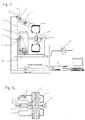
- FIG. 1 shows a simplified schematic illustration of a device for testing tires according to an exemplary embodiment of the invention.
- the tire 1 is mounted on a rim 2 and rotatably supported about the roll axis about the axis 3 relative to the test stand 4. Via a compressed air supply 13 with a compressed air regulator 14, the tire pressure can also be varied when the tire is rotating.
- the test system has a light section system, which is firmly connected to the test stand 4 via the holder 7, consisting of a camera 8 and a device 11 for projecting light sections.
- the camera 8 can be a commercially available video camera.
- the device 11 for projecting light sections consists, for example, of a laser scanner or a laser whose beam is expanded by means of a cylindrical lens.
- the image data recorded by the camera 8 are transmitted to an image processing system 12 for further processing.
- the image recording of the camera 8 is also triggered by the image processing system 12 via a trigger signal.
- the axis 3 is driven by the motor 15 and rotates the tire at a constant speed during the measurement.
- an index mark 5 sits on the axis of rotation 3 and is detected by the sensor 6.
- the signal generated when the index mark 5 passes the sensor 6 is used by the image processing system 12 as a synchronization pulse.
- the camera 8 is synchronized with the rotary movement only once per axis revolution and otherwise runs freely.
- the defined rotational positions are determined by the time frame of the image recording by the camera 8 and the rotational speed of the axle drive. This procedure is sufficiently precise since the time behavior of modern video cameras is extremely precise.
- the camera 8 is equipped according to one aspect of the invention with anamorphic optics 9, in which the imaging scales in the image plane differ in the horizontal and vertical directions are.
- the imaging scales are selected independently of one another so that on the one hand the side wall and tire shoulder are completely grasped in the radial direction and on the other hand the resolution in the triangulation plane is as large as possible.
- the camera is housed in a protective housing 10.
- Such a protective housing is advantageously also fitted around the device 11.
- the light cutting system is aligned so that the device 11 generates light cuts that cut the side wall of the tire 1 in the radial direction and extend over the tire shoulder into the tread area.
- the camera 8 is oriented such that the projected light section is completely captured both on the side wall and in the shoulder area of the tire 1.
- the light section plane is projected obliquely by the device 11 onto the side wall of the tire.
- the tire 1 is rotated about the axis 3 at a frequency of approximately 0.5 Hz.
- 50 light sections can be captured on the circumference.
- the number of light cuts is correspondingly higher. If a video camera working in interlaced mode is used and each field is exposed separately, this number can be doubled, the number of image lines and thus the number of measuring points per picture being halved.
- Figure 2 shows the test system shown in Figure 1 in plan view. It is particular here the one lying between the optical axes of the device 11 and the camera 8 Recognize triangulation angles.
- FIG. 3 shows the position of the light sections when measuring the tire sidewall the test system shown in Figure 1 and Figure 2.
- the direction of rotation shown of the tire 1 or the rim 2 are at a rotational frequency of the tire of 0.5 Hz and an image recording frequency of 25 Hz, the 50 light sections L1 to L50 generated or measured.
- the Contour lines L1 to L50 With 50 light sections from the circumference of the tire you get the Contour lines L1 to L50 at a distance of 7.2 ° each.
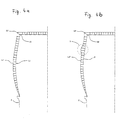
- FIG. 4a shows the change in a contour line when the tire pressure increases.
- the Contour line L1 corresponds to a low pressure, the contour line L1 'to a higher one Print.
- the outermost point of the tire shoulder S1 shifts to point S1 '. Since the tire shoulder is geometrically clearly defined, it can be shifted S1 ⁇ S1 'and others the total elongation of the contour line can be calculated.
- the stretches can be determined very precisely because all reference lengths are in true size or can be determined.
- FIG. 4b shows the behavior of the tire when the pressure is increased if there is a structural defect is present.
- the contour line L2 corresponds to a low pressure, the contour line L2 'to one higher pressure.
- FIG. 5a schematically shows the procedure for calculating the pure axial displacements with elimination of the radial change in strain.
- the contour line L1 is measured at a low initial pressure and shows a pronounced surface relief both in the side wall and in the tread.
- the tire expands and the contour line L1 'is measured during the new measurement.
- the corners of the surface relief shift both in the radial and in the axial direction.
- the elongation of the contour line L1 'with respect to the contour line L1 in the radial direction is first determined and then eliminated by calculation. This results in the contour line L1 ".
- the shape change behavior along the contour line L1 in the axial direction is then determined by point-by-point determination of the axial distance between the contour lines L1 and L1".
- the determination of the radial change in elongation can be determined, for example, by calculating the radial displacement of the shoulder corner point S1. All displacements are advantageously measured with respect to the detected points by the rim 2.
- the elongation of the contour line L1 'with respect to the contour line L1 in the radial direction is calculated from the distances FS1 and FS1'.
- FIG. 5b schematically shows the procedure for calculating the pure radial Displacements with elimination of the axial strain.
- the radial shift To calculate the identical surface points, first the stretch of the contour line L1 'determined with respect to the contour line L1 in the axial direction and then mathematically eliminated. This creates the contour line L1 '' '. The shape change behavior is then compared along the contour line L1 in the radial direction by comparison of the contour lines L1 and L1 '' '.
Landscapes
- Physics & Mathematics (AREA)
- General Physics & Mathematics (AREA)
- Length Measuring Devices By Optical Means (AREA)
- Tires In General (AREA)
Applications Claiming Priority (2)
| Application Number | Priority Date | Filing Date | Title |
|---|---|---|---|
| DE10019386A DE10019386C2 (de) | 2000-04-19 | 2000-04-19 | Verfahren und Vorrichtung zur Prüfung von Reifen |
| DE10019386 | 2000-04-19 |
Publications (4)
| Publication Number | Publication Date |
|---|---|
| EP1148328A2 true EP1148328A2 (fr) | 2001-10-24 |
| EP1148328A3 EP1148328A3 (fr) | 2003-12-17 |
| EP1148328B1 EP1148328B1 (fr) | 2005-11-23 |
| EP1148328B2 EP1148328B2 (fr) | 2016-12-28 |
Family
ID=7639305
Family Applications (1)
| Application Number | Title | Priority Date | Filing Date |
|---|---|---|---|
| EP01109655.9A Expired - Lifetime EP1148328B2 (fr) | 2000-04-19 | 2001-04-19 | Procédé et dispositif d'essai optique de pneus |
Country Status (3)
| Country | Link |
|---|---|
| US (1) | US6615650B2 (fr) |
| EP (1) | EP1148328B2 (fr) |
| DE (2) | DE10019386C2 (fr) |
Cited By (4)
| Publication number | Priority date | Publication date | Assignee | Title |
|---|---|---|---|---|
| WO2005121698A1 (fr) | 2004-06-03 | 2005-12-22 | Snap-On Incorporated | Systeme et procede sans contact d'analyse de pneus |
| EP1647817A2 (fr) | 2004-10-15 | 2006-04-19 | Steinbichler Optotechnik Gmbh | Méthode et dispositif pour test optique de surface de roue |
| US7053761B2 (en) * | 2000-02-28 | 2006-05-30 | Donnelly Corporation | Vehicular tire pressure monitoring system |
| US10311835B1 (en) | 2012-06-01 | 2019-06-04 | Hunter Engineering Company | Method for detection and estimation of tire tread wear |
Families Citing this family (49)
| Publication number | Priority date | Publication date | Assignee | Title |
|---|---|---|---|---|
| US6326613B1 (en) | 1998-01-07 | 2001-12-04 | Donnelly Corporation | Vehicle interior mirror assembly adapted for containing a rain sensor |
| US6124886A (en) | 1997-08-25 | 2000-09-26 | Donnelly Corporation | Modular rearview mirror assembly |
| US8288711B2 (en) | 1998-01-07 | 2012-10-16 | Donnelly Corporation | Interior rearview mirror system with forwardly-viewing camera and a control |
| US6278377B1 (en) | 1999-08-25 | 2001-08-21 | Donnelly Corporation | Indicator for vehicle accessory |
| US6420975B1 (en) | 1999-08-25 | 2002-07-16 | Donnelly Corporation | Interior rearview mirror sound processing system |
| WO2001064481A2 (fr) | 2000-03-02 | 2001-09-07 | Donnelly Corporation | Systeme de miroir video integrant un module accessoire |
| US7480149B2 (en) | 2004-08-18 | 2009-01-20 | Donnelly Corporation | Accessory module for vehicle |
| US6396408B2 (en) | 2000-03-31 | 2002-05-28 | Donnelly Corporation | Digital electrochromic circuit with a vehicle network |
| JP4363506B2 (ja) * | 2000-08-10 | 2009-11-11 | 横浜ゴム株式会社 | 空気入りタイヤのトレッド摩耗量測定方法 |
| JP2003220811A (ja) * | 2002-01-30 | 2003-08-05 | Sumitomo Rubber Ind Ltd | タイヤ空気圧低下検出方法および装置、ならびにタイヤ減圧判定のプログラム |
| WO2003065084A1 (fr) | 2002-01-31 | 2003-08-07 | Donnelly Corporation | Module d'accessoires de vehicule |
| EP1547828B1 (fr) * | 2003-11-25 | 2010-10-20 | Sumitomo Rubber Industries Limited | Procédé et appareil de détection d'une baisse de pression dans un pneumatique, et programme pour juger cette baisse de pression |
| US8256821B2 (en) | 2004-12-15 | 2012-09-04 | Magna Donnelly Engineering Gmbh | Accessory module system for a vehicle window |
| DE102004062412B4 (de) * | 2004-12-23 | 2007-02-01 | Mähner, Bernward | Verfahren zur räumlichen Vermessung sich schnell bewegender Objekte |
| EP1996897B2 (fr) * | 2006-03-23 | 2014-10-22 | Bernward Mähner | Procédé de mesure spatiale d'objets à déplacement rapide |
| DE102006015123B4 (de) * | 2006-03-31 | 2008-03-20 | Mähner, Bernward | Vorrichtung und Verfahren zum Prüfen eines Reifens, insbesondere mittels eines interferometrischen Messverfahrens |
| JP4977415B2 (ja) * | 2006-07-21 | 2012-07-18 | 株式会社ブリヂストン | タイヤ検査用基準形状データの作成装置および作成方法 |
| US7677077B2 (en) * | 2006-12-21 | 2010-03-16 | The Goodyear Tire & Rubber Company | Sensor calibration device and method for a tire |
| US8087301B2 (en) * | 2007-09-24 | 2012-01-03 | Infineon Technologies Ag | Optical systems and methods for determining tire characteristics |
| DE102007056967B4 (de) | 2007-11-27 | 2009-09-17 | Mähner, Bernward | Verfahren und Vorrichtung zur Herstellung formtreuer Reifen |
| DE102007062105B4 (de) | 2007-12-21 | 2011-06-22 | Mähner, Bernward, 82205 | Vorrichtung und Verfahren zur Prüfung und räumlichen Vermessung sich drehender Objekte, insbesondere von Reifen |
| EP2110656B1 (fr) * | 2008-04-14 | 2011-07-06 | Snap-on Equipment Srl a unico socio | Appareil pour déterminer l'état d'un ensemble de roue |
| DE102008037356C5 (de) | 2008-08-12 | 2020-09-17 | Bernward Mähner | Stapelmodul und Zentriermodul für eine Prüfanlage zum Prüfen von Reifen |
| US7805987B1 (en) * | 2008-08-19 | 2010-10-05 | Smith Bradley R | System and method for pneumatic tire defect detection |
| US8570374B2 (en) | 2008-11-13 | 2013-10-29 | Magna Electronics Inc. | Camera for vehicle |
| DE102009008468B4 (de) | 2009-02-15 | 2017-08-31 | Bernward Mähner | Verfahren zur Prüfung von Reifen |
| DE102009008470A1 (de) | 2009-02-15 | 2010-08-26 | Mähner, Bernward | Verfahren und Vorrichtung zur räumlichen Vermessung eines sich bewegenden Objektes |
| IT1394907B1 (it) * | 2009-07-22 | 2012-07-20 | Bridgestone Corp | Metodo ed impianto di ricostruzione di un pneumatico |
| WO2011065938A1 (fr) * | 2009-11-24 | 2011-06-03 | Michelin Recherche Et Technique, S.A. | Test sur véhicule de la résistance d'un pneu à une agression latérale |
| DE102010006105A1 (de) * | 2010-01-28 | 2011-08-18 | Siemens Aktiengesellschaft, 80333 | Vorrichtung und Verfahren zur sequentiellen Musterprojektion |
| JP5562278B2 (ja) * | 2011-03-15 | 2014-07-30 | 株式会社神戸製鋼所 | タイヤ形状検査装置、及びタイヤ形状検査方法 |
| DE102011076068A1 (de) * | 2011-05-18 | 2012-11-22 | Bayerische Motoren Werke Aktiengesellschaft | Verfahren und Vorrichtung zur Fahrzeugrad-Kontrolle |
| US8843269B2 (en) * | 2011-08-17 | 2014-09-23 | Deere & Company | Vehicle soil pressure management based on topography |
| US9511633B2 (en) | 2011-08-17 | 2016-12-06 | Deere & Company | Soil compaction management and reporting |
| ITMI20112253A1 (it) | 2011-12-13 | 2013-06-14 | Pirelli | Metodo per controllare la deposizione di semilavorati elementari in un processo di confezione di pneumatici per ruote di veicoli |
| EP2920566A4 (fr) * | 2012-11-15 | 2016-07-13 | Android Ind Llc | Système et procédé de détermination de l'uniformité d'un pneu |
| DE102013102296B4 (de) | 2012-12-21 | 2018-11-08 | Bernward Mähner | Vorrichtung und Verfahren zum Prüfen eines Reifens mittels eines interferometrischen Messverfahrens |
| DE102013104004A1 (de) * | 2013-04-19 | 2014-10-23 | Schoen + Sandt Machinery Gmbh | Prüfvorrichtung und -Verfahren |
| WO2015097635A1 (fr) * | 2013-12-23 | 2015-07-02 | Pirelli Tyre S.P.A. | Procédé et appareil pour détecter les défauts sur les pneus dans un processus de production de pneus |
| CA2952947A1 (fr) | 2014-06-19 | 2015-12-23 | Neomatix Ltd. | Systeme et procede de detection et d'analyse de caracteristiques multiples d'un pneu en rotation |
| CN104527337A (zh) * | 2014-12-01 | 2015-04-22 | 深圳市元征科技股份有限公司 | 一种轮胎胎压的检测方法、装置及移动设备和照相设备 |
| US10697858B2 (en) | 2015-12-16 | 2020-06-30 | Pirelli Tyre S.P.A. | Method and device for checking tyres |
| CN107848348A (zh) * | 2016-06-30 | 2018-03-27 | 华为技术有限公司 | 一种爆胎预警方法及装置 |
| IT201700016046A1 (it) | 2017-02-14 | 2018-08-14 | Tekna Automazione E Controllo S R L | Apparato per il rilevamento e la verifica di difetti superficiali di un pneumatico al termine di un processo di produzione |
| WO2018229805A1 (fr) * | 2017-06-12 | 2018-12-20 | Pirelli Tyre S.P.A. | Procédé pour contrôler des pneus |
| US11112239B1 (en) | 2017-11-10 | 2021-09-07 | Hunter Engineering Company | Method for tire shoulder tread wear evaluation |
| CN111238834A (zh) * | 2020-01-20 | 2020-06-05 | 东莞市秉能橡胶有限公司 | 一种轮胎测量方法 |
| JP7554447B2 (ja) * | 2020-03-04 | 2024-09-20 | 学校法人自治医科大学 | 撮像システム及び車両 |
| CN113945163B (zh) * | 2021-09-07 | 2025-03-14 | 通力轮胎有限公司 | 一种充气式轮胎断面扫描装置及方法 |
Family Cites Families (9)
| Publication number | Priority date | Publication date | Assignee | Title |
|---|---|---|---|---|
| US4745469A (en) * | 1987-02-18 | 1988-05-17 | Perceptron, Inc. | Vehicle wheel alignment apparatus and method |
| US5313827A (en) * | 1992-09-28 | 1994-05-24 | The Goodyear Tire & Rubber Company | Method and apparatus for detecting ply defects in pneumatic tires |
| US5703680A (en) * | 1996-01-16 | 1997-12-30 | The Goodyear Tire & Rubber Company | Method for dynamic interference pattern testing |
| GB2314928B (en) * | 1996-07-04 | 2001-02-14 | Sun Electric Uk Ltd | Tyre condition assessment |
| ES2188696T3 (es) * | 1996-08-06 | 2003-07-01 | Nova C O R D Ag | Procedimiento para detectar los defectos de los neumaticos. |
| AU6294398A (en) * | 1997-02-03 | 1998-08-25 | Joachim Burger | Method and device for measuring the pattern depth on a tyre |
| US5987978A (en) * | 1997-04-02 | 1999-11-23 | Assembly Technology & Test Ltd. | Apparatus for testing tire tread depth |
| DE19731486C2 (de) * | 1997-07-22 | 2001-02-22 | Beissbarth Gmbh | Reifenprüfvorrichtung |
| DE19849793C1 (de) * | 1998-10-28 | 2000-03-16 | Fraunhofer Ges Forschung | Vorrichtung und Verfahren zur berührungslosen Erfassung von Unebenheiten in einer gewölbten Oberfläche |
-
2000
- 2000-04-19 DE DE10019386A patent/DE10019386C2/de not_active Expired - Fee Related
-
2001
- 2001-04-19 EP EP01109655.9A patent/EP1148328B2/fr not_active Expired - Lifetime
- 2001-04-19 DE DE50108131T patent/DE50108131D1/de not_active Expired - Lifetime
- 2001-08-13 US US09/927,336 patent/US6615650B2/en not_active Expired - Fee Related
Cited By (8)
| Publication number | Priority date | Publication date | Assignee | Title |
|---|---|---|---|---|
| US7053761B2 (en) * | 2000-02-28 | 2006-05-30 | Donnelly Corporation | Vehicular tire pressure monitoring system |
| US7460007B2 (en) | 2000-02-28 | 2008-12-02 | Donnelly Corporation | Console system suitable for use in an interior cabin of a vehicle |
| WO2005121698A1 (fr) | 2004-06-03 | 2005-12-22 | Snap-On Incorporated | Systeme et procede sans contact d'analyse de pneus |
| US7269997B2 (en) | 2004-06-03 | 2007-09-18 | Snap-On Incorporated | Non-contact method and system for tire analysis |
| CN100565100C (zh) * | 2004-06-03 | 2009-12-02 | 斯耐普昂公司 | 用于轮胎分析的非接触方法和系统 |
| EP1647817A2 (fr) | 2004-10-15 | 2006-04-19 | Steinbichler Optotechnik Gmbh | Méthode et dispositif pour test optique de surface de roue |
| EP1647817A3 (fr) * | 2004-10-15 | 2011-12-07 | Steinbichler Optotechnik GmbH | Méthode et dispositif pour test optique de surface de roue |
| US10311835B1 (en) | 2012-06-01 | 2019-06-04 | Hunter Engineering Company | Method for detection and estimation of tire tread wear |
Also Published As
| Publication number | Publication date |
|---|---|
| US20010052259A1 (en) | 2001-12-20 |
| EP1148328B1 (fr) | 2005-11-23 |
| DE10019386C2 (de) | 2003-04-03 |
| EP1148328B2 (fr) | 2016-12-28 |
| DE10019386A1 (de) | 2001-10-31 |
| EP1148328A3 (fr) | 2003-12-17 |
| DE50108131D1 (de) | 2005-12-29 |
| US6615650B2 (en) | 2003-09-09 |
Similar Documents
| Publication | Publication Date | Title |
|---|---|---|
| DE10019386C2 (de) | Verfahren und Vorrichtung zur Prüfung von Reifen | |
| DE19849793C1 (de) | Vorrichtung und Verfahren zur berührungslosen Erfassung von Unebenheiten in einer gewölbten Oberfläche | |
| DE102007009040C5 (de) | Vorrichtung und Verfahren zum Prüfen eines Reifens, insbesondere mittels eines interferometrischen Messverfahrens | |
| DE4231578C2 (de) | Verfahren zur Ermittlung von Verformungen an einem Prüfobjekt mit diffus streuender Oberfläche, insbesondere an Reifen, sowie Vorrichtung zur Durchführung des Verfahrens | |
| EP2002235B1 (fr) | Dispositif et procede de controle d'un pneumatique, en particulier au moyen d'une mesure interferometrique | |
| EP3787900B1 (fr) | Méthode d'investigation d'un cylindre pour imprimer et dispositif correspondant | |
| EP1500917B1 (fr) | Procédé et dispositif d'essai de pneus | |
| WO1999004248A1 (fr) | Procede de detection automatique de defauts superficiels au niveau de carrosseries brutes et dispositif permettant de mettre ledit procede en oeuvre | |
| WO2007110414A1 (fr) | Dispositif et procédé pour vérifier un pneumatique, notamment au moyen d'un procédé de mesure interférométrie | |
| EP1647817B1 (fr) | Méthode et dispositif pour test optique de surface de roue | |
| EP1394503B1 (fr) | Dispositif pour mesurer la profondeur d'un profil | |
| DE102006062447B4 (de) | Verfahren und Vorrichtung zur Erfassung der dreidimensionalen Oberfläche eines Objekts, insbesondere eines Fahrzeugreifens | |
| EP1284409A1 (fr) | Procédé et appareil pour l'inspection de la déformation d'objets | |
| EP3545259B1 (fr) | Procédé et dispositif d'analyse d'objets de test à symétrie de révolution | |
| DE102020203983A1 (de) | Verfahren zur OCT-Schweißnahtüberwachung sowie zugehörige Laserbearbeitungsmaschine und Computerprogrammprodukt | |
| EP0884574B1 (fr) | Procédé et dispositif d'essai de pneus | |
| DE10019387C2 (de) | Verfahren und Vorrichtung zur Untersuchung von Reifen | |
| DE102006014058B4 (de) | Vorrichtung und Verfahren zum optischen Prüfen eines Reifens | |
| EP1775548A2 (fr) | Procédé et dispositif pour la détection de la déformation d'objets | |
| DE102009008468B4 (de) | Verfahren zur Prüfung von Reifen | |
| DE102019121662A1 (de) | Verfahren zur Prüfung eines Reifens | |
| DE10009870C2 (de) | Verfahren und Vorrichtung zur Untersuchung von Prüfobjekten | |
| DE2927410A1 (de) | Anordnung zur ueberwachung des laengsprofils von geschliffenen zylinderbolzen | |
| WO2024179838A1 (fr) | Dispositif d'essai et procédé d'enregistrement optique d'une roue orientable d'un véhicule à moteur, et banc d'essai de véhicule comprenant le dispositif d'essai | |
| EP4733715A1 (fr) | Mesure optique avec mouvement d'axes |
Legal Events
| Date | Code | Title | Description |
|---|---|---|---|
| PUAI | Public reference made under article 153(3) epc to a published international application that has entered the european phase |
Free format text: ORIGINAL CODE: 0009012 |
|
| AK | Designated contracting states |
Kind code of ref document: A2 Designated state(s): AT BE CH CY DE DK ES FI FR GB GR IE IT LI LU MC NL PT SE TR |
|
| AX | Request for extension of the european patent |
Free format text: AL;LT;LV;MK;RO;SI |
|
| RAP1 | Party data changed (applicant data changed or rights of an application transferred) |
Owner name: MAEHNER, BERNWARD Owner name: DENGLER, STEFAN |
|
| PUAL | Search report despatched |
Free format text: ORIGINAL CODE: 0009013 |
|
| AK | Designated contracting states |
Kind code of ref document: A3 Designated state(s): AT BE CH CY DE DK ES FI FR GB GR IE IT LI LU MC NL PT SE TR |
|
| AX | Request for extension of the european patent |
Extension state: AL LT LV MK RO SI |
|
| 17P | Request for examination filed |
Effective date: 20040616 |
|
| AKX | Designation fees paid |
Designated state(s): DE FR IT |
|
| 17Q | First examination report despatched |
Effective date: 20041018 |
|
| GRAP | Despatch of communication of intention to grant a patent |
Free format text: ORIGINAL CODE: EPIDOSNIGR1 |
|
| GRAS | Grant fee paid |
Free format text: ORIGINAL CODE: EPIDOSNIGR3 |
|
| GRAA | (expected) grant |
Free format text: ORIGINAL CODE: 0009210 |
|
| AK | Designated contracting states |
Kind code of ref document: B1 Designated state(s): DE FR IT |
|
| REF | Corresponds to: |
Ref document number: 50108131 Country of ref document: DE Date of ref document: 20051229 Kind code of ref document: P |
|
| ET | Fr: translation filed | ||
| PLBI | Opposition filed |
Free format text: ORIGINAL CODE: 0009260 |
|
| PLAX | Notice of opposition and request to file observation + time limit sent |
Free format text: ORIGINAL CODE: EPIDOSNOBS2 |
|
| 26 | Opposition filed |
Opponent name: STEINBICHLER OPTOTECHNIK GMBH Effective date: 20060822 |
|
| PLBB | Reply of patent proprietor to notice(s) of opposition received |
Free format text: ORIGINAL CODE: EPIDOSNOBS3 |
|
| PLAS | Information related to reply of patent proprietor to notice(s) of opposition deleted |
Free format text: ORIGINAL CODE: EPIDOSDOBS3 |
|
| PLBB | Reply of patent proprietor to notice(s) of opposition received |
Free format text: ORIGINAL CODE: EPIDOSNOBS3 |
|
| PLAY | Examination report in opposition despatched + time limit |
Free format text: ORIGINAL CODE: EPIDOSNORE2 |
|
| PLAH | Information related to despatch of examination report in opposition + time limit modified |
Free format text: ORIGINAL CODE: EPIDOSCORE2 |
|
| PLBC | Reply to examination report in opposition received |
Free format text: ORIGINAL CODE: EPIDOSNORE3 |
|
| PLAB | Opposition data, opponent's data or that of the opponent's representative modified |
Free format text: ORIGINAL CODE: 0009299OPPO |
|
| PLAZ | Examination of admissibility of opposition: despatch of communication + time limit |
Free format text: ORIGINAL CODE: EPIDOSNOPE2 |
|
| PLBA | Examination of admissibility of opposition: reply received |
Free format text: ORIGINAL CODE: EPIDOSNOPE4 |
|
| APBM | Appeal reference recorded |
Free format text: ORIGINAL CODE: EPIDOSNREFNO |
|
| APBP | Date of receipt of notice of appeal recorded |
Free format text: ORIGINAL CODE: EPIDOSNNOA2O |
|
| APAH | Appeal reference modified |
Free format text: ORIGINAL CODE: EPIDOSCREFNO |
|
| APBQ | Date of receipt of statement of grounds of appeal recorded |
Free format text: ORIGINAL CODE: EPIDOSNNOA3O |
|
| PGFP | Annual fee paid to national office [announced via postgrant information from national office to epo] |
Ref country code: IT Payment date: 20140428 Year of fee payment: 14 Ref country code: DE Payment date: 20140424 Year of fee payment: 14 Ref country code: FR Payment date: 20140416 Year of fee payment: 14 |
|
| REG | Reference to a national code |
Ref country code: DE Ref legal event code: R119 Ref document number: 50108131 Country of ref document: DE |
|
| PG25 | Lapsed in a contracting state [announced via postgrant information from national office to epo] |
Ref country code: DE Free format text: LAPSE BECAUSE OF NON-PAYMENT OF DUE FEES Effective date: 20151103 Ref country code: IT Free format text: LAPSE BECAUSE OF NON-PAYMENT OF DUE FEES Effective date: 20150419 |
|
| REG | Reference to a national code |
Ref country code: FR Ref legal event code: ST Effective date: 20151231 |
|
| PG25 | Lapsed in a contracting state [announced via postgrant information from national office to epo] |
Ref country code: FR Free format text: LAPSE BECAUSE OF NON-PAYMENT OF DUE FEES Effective date: 20150430 |
|
| APBU | Appeal procedure closed |
Free format text: ORIGINAL CODE: EPIDOSNNOA9O |
|
| PUAH | Patent maintained in amended form |
Free format text: ORIGINAL CODE: 0009272 |
|
| STAA | Information on the status of an ep patent application or granted ep patent |
Free format text: STATUS: PATENT MAINTAINED AS AMENDED |
|
| 27A | Patent maintained in amended form |
Effective date: 20161228 |
|
| AK | Designated contracting states |
Kind code of ref document: B2 Designated state(s): DE FR IT |
|
| REG | Reference to a national code |
Ref country code: DE Ref legal event code: R102 Ref document number: 50108131 Country of ref document: DE |