EP1148364A2 - Zugentlastungsmechanismus für einen Glasfaserstecker - Google Patents
Zugentlastungsmechanismus für einen Glasfaserstecker Download PDFInfo
- Publication number
- EP1148364A2 EP1148364A2 EP01104306A EP01104306A EP1148364A2 EP 1148364 A2 EP1148364 A2 EP 1148364A2 EP 01104306 A EP01104306 A EP 01104306A EP 01104306 A EP01104306 A EP 01104306A EP 1148364 A2 EP1148364 A2 EP 1148364A2
- Authority
- EP
- European Patent Office
- Prior art keywords
- clamp
- crimpable
- optical fiber
- housing
- state
- Prior art date
- Legal status (The legal status is an assumption and is not a legal conclusion. Google has not performed a legal analysis and makes no representation as to the accuracy of the status listed.)
- Withdrawn
Links
- 239000013307 optical fiber Substances 0.000 title claims abstract description 34
- 230000007246 mechanism Effects 0.000 title claims description 22
- 239000004697 Polyetherimide Substances 0.000 claims description 3
- 229920001601 polyetherimide Polymers 0.000 claims description 3
- 239000000835 fiber Substances 0.000 abstract description 20
- 238000002788 crimping Methods 0.000 abstract description 9
- 238000005452 bending Methods 0.000 abstract description 6
- 230000005540 biological transmission Effects 0.000 description 2
- 238000000034 method Methods 0.000 description 2
- 230000008569 process Effects 0.000 description 2
- 238000005728 strengthening Methods 0.000 description 2
- 230000009471 action Effects 0.000 description 1
- 239000004760 aramid Substances 0.000 description 1
- 229920003235 aromatic polyamide Polymers 0.000 description 1
- 238000005253 cladding Methods 0.000 description 1
- 230000003993 interaction Effects 0.000 description 1
- 239000000463 material Substances 0.000 description 1
- 230000004048 modification Effects 0.000 description 1
- 238000012986 modification Methods 0.000 description 1
- 229920001296 polysiloxane Polymers 0.000 description 1
- 229920001169 thermoplastic Polymers 0.000 description 1
- 239000004416 thermosoftening plastic Substances 0.000 description 1
Images

Classifications
-
- G—PHYSICS
- G02—OPTICS
- G02B—OPTICAL ELEMENTS, SYSTEMS OR APPARATUS
- G02B6/00—Light guides; Structural details of arrangements comprising light guides and other optical elements, e.g. couplings
- G02B6/24—Coupling light guides
- G02B6/36—Mechanical coupling means
- G02B6/38—Mechanical coupling means having fibre to fibre mating means
- G02B6/3807—Dismountable connectors, i.e. comprising plugs
- G02B6/3833—Details of mounting fibres in ferrules; Assembly methods; Manufacture
- G02B6/3846—Details of mounting fibres in ferrules; Assembly methods; Manufacture with fibre stubs
-
- G—PHYSICS
- G02—OPTICS
- G02B—OPTICAL ELEMENTS, SYSTEMS OR APPARATUS
- G02B6/00—Light guides; Structural details of arrangements comprising light guides and other optical elements, e.g. couplings
- G02B6/24—Coupling light guides
- G02B6/36—Mechanical coupling means
- G02B6/38—Mechanical coupling means having fibre to fibre mating means
- G02B6/3807—Dismountable connectors, i.e. comprising plugs
- G02B6/3887—Anchoring optical cables to connector housings, e.g. strain relief features
- G02B6/3888—Protection from over-extension or over-compression
-
- G—PHYSICS
- G02—OPTICS
- G02B—OPTICAL ELEMENTS, SYSTEMS OR APPARATUS
- G02B6/00—Light guides; Structural details of arrangements comprising light guides and other optical elements, e.g. couplings
- G02B6/24—Coupling light guides
- G02B6/36—Mechanical coupling means
- G02B6/38—Mechanical coupling means having fibre to fibre mating means
- G02B6/3807—Dismountable connectors, i.e. comprising plugs
- G02B6/381—Dismountable connectors, i.e. comprising plugs of the ferrule type, e.g. fibre ends embedded in ferrules, connecting a pair of fibres
- G02B6/3818—Dismountable connectors, i.e. comprising plugs of the ferrule type, e.g. fibre ends embedded in ferrules, connecting a pair of fibres of a low-reflection-loss type
- G02B6/382—Dismountable connectors, i.e. comprising plugs of the ferrule type, e.g. fibre ends embedded in ferrules, connecting a pair of fibres of a low-reflection-loss type with index-matching medium between light guides
-
- G—PHYSICS
- G02—OPTICS
- G02B—OPTICAL ELEMENTS, SYSTEMS OR APPARATUS
- G02B6/00—Light guides; Structural details of arrangements comprising light guides and other optical elements, e.g. couplings
- G02B6/24—Coupling light guides
- G02B6/36—Mechanical coupling means
- G02B6/38—Mechanical coupling means having fibre to fibre mating means
- G02B6/3807—Dismountable connectors, i.e. comprising plugs
- G02B6/3833—Details of mounting fibres in ferrules; Assembly methods; Manufacture
- G02B6/3855—Details of mounting fibres in ferrules; Assembly methods; Manufacture characterised by the method of anchoring or fixing the fibre within the ferrule
Definitions
- the present invention relates generally to a fiber optic termination and more particularly to a clamp for locking the optical fiber against movement.
- the present invention is a clamping mechanism for the optical fiber of a fiber optic cable.
- the mechanism includes a crimpable housing, adapted to receive first and second clamp members.
- the housing defines a central longitudinal axis.
- the first clamp member is substantially semi-cylindrical in shape, defining a central longitudinal groove which substantially aligns with the longitudinal axis of the housing in a first or crimpable state.
- the first clamp member has opposed, rounded longitudinal ridges defining a clamp seat therebetween.
- the housing further receives the second clamp member in the crimpable state.
- the second clamp member rests within the clamp seat.
- the first and second clamp members cooperate to guide the optical fiber towards and along the central longitudinal groove.
- the optical fiber extends between and beyond the first and second clamp members, at least partially residing within the central longitudinal groove.
- the housing urges the second clamp member towards the clamp seat, thereby "pinching" the optical fiber.
- the second clamp member includes an exit chamfer substantially opposite the central longitudinal groove of the first clamp member. Crimping of the housing exerts a bending force upon the optical fiber, which may itself cause a transmission "gap." The exit chamfer substantially negates this bending force.
- Another object is a clamp to retain the optical fiber against movement within the termination. Still another object is a fiber optic clamp that substantially avoids bending of the optical fiber during the termination process. Yet another object is an inexpensive, readily manufactured clamping mechanism for a optical fiber.
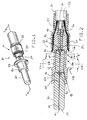
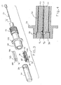
- FIGURES 1-6 A preferred embodiment of the present invention is shown in FIGURES 1-6 as a clamping mechanism, generally designated 10, for an optical fiber 12 of a conventional fiber optic cable 14.
- the fiber optic cable 14 includes an outer jacket 16, strengthening members 18 (typically an aramid yarn), and a buffer jacket 20.
- the clamping mechanism 10 is utilized in a jacketed stub termination, generally designated 22.
- the clamping mechanism 10 may also be used in a jacketed pass-through termination, a buffered stub termination and a buffered pass-through termination.
- the clamping mechanism 10 has a crimpable state, as best shown in FIGURE 2, and a crimped state, as best shown in FIGURE 6.
- the clamping mechanism 10 and termination 22 are assembled in the crimpable state and operative to clamp the optical fiber 12 in the crimped state.
- the mechanism 10 includes a crimpable housing 24, a first clamp member 26 and a second clamp member 28.
- the housing 24 is adapted to receive the first and second clamp members 26, 28 in the crimpable state and to secure the clamp members 26, 28 in the crimped state.
- the termination 22 includes a ferrule 30 and a crimping member 32. As shown, the ferrule 30 has a central longitudinal passageway 34 and a radially extending notch 36, exposing the central passageway 34. A stud optical fiber 38 extends from a termination end 40 to a point visible through the notch 36. During assembly of the termination 22, an index-matching gel (not shown) is applied to the stud fiber 38, through the notch 36, to effectively coupled the optical fiber 12 to the stud fiber 38. Excess gel is then removed from the notch 36.
- the housing 24 has a ferrule end 42 and a cable end 44.
- the ferrule end 42 defines a substantially cylindrical ferrule channel 46, terminating at an annular ferrule stop wall 48, adapted to receive and frictionally retain the ferrule 30.
- the cable end 44 defines a substantially cylindrical cable channel 50 adapted to receive the optical fiber 12 and buffer jacket 20.
- the cable end 44 has an external knurled surface 52 to facilitate connection of the fiber optic cable 14 to the crimpable housing 24. More particularly, the crimping member 32 affixes the strengthening members 18 to the knurled surface 52 of the cable end 44 to substantially avoid undue loading of the optical fiber 12.
- the housing 24 further defines a substantially cylindrical clamp channel 54, interposed the ferrule channel 46 and cable channel 50. As best shown in FIGURE 2, the diameter of the clamp channel 54 is less than the diameter of the ferrule channel 46 and greater than the diameter of the cable channel 50, so as to provide a clamp stop wall 56.
- the channels 46, 50, 54 are substantially coaxial, such that the housing 24 has a central longitudinal axis, designated "A" in FIGURE 3.
- the housing 24 includes a radially extending collar 58, encompassing the clamp channel 54 substantially adjacent the ferrule stop wall 48.
- the collar 58 facilitates assembly of the termination 22.
- the housing 24 is designed to be crimped in the region of the clamp channel 54 near the collar 58, designated "B" in FIGURE 2.
- a conventional crimping tool (not shown) is used to crimp both the housing 24 and crimping member 32.
- the first clamp member 26 is substantially semi-cylindrical, having a first entrance end 60 and a first exit end 62.
- the first clamp member 26 has a longitudinally extending, substantially planar central region 64.
- a groove 66 extends longitudinally at the center of the planar region 64.
- the first clamp member 26 has opposed, rounded ridges 68, 70, respectively, extending along the longitudinal edges thereof.
- the rounded ridges 68, 70 border the central planar region 64 and define a clamp seat 72 therebetween.
- the groove 66 is preferably V-shaped, with the walls thereof forming substantially a right angle.
- the depth is preferably about 0.0035 inches.
- the first clamp member 26 is positioned within the clamp channel 54, abutting the clamp stop wall 56.
- the groove 66 substantially aligns with the central longitudinal axis "A" of the housing 24.
- the second clamp member 28 is generally rectangular in shape. In this preferred embodiment, two corners 74, 76 are rounded to facilitate assembly of the termination 22.
- the second clamp member 28 has a second entrance end 78 and a second exit end 80.
- the lengths of the first and second clamp members 26, 28 are substantially equivalent, such that the first and second entrance ends 60, 78 and the first and second exit ends 62, 80 substantially align in the crimpable and crimped states.
- the second clamp member 28 is received by the crimpable housing 24.
- the clamp member 28 In the crimpable state, the clamp member 28 generally rests in the clamp seat 72 against the clamp stop wall 56.
- the first and second entrance ends 60, 78 have first and second, central entrance chamfers 82, 84, respectively.
- the chamfers 82, 84 cooperatively provide a substantially conical clamp port, generally designated 86, tapering toward the longitudinal groove 66.
- the first and second clamp members 26, 28 cooperatively defining guide means, generally designated 88, for directing the optical fiber 12 towards and at least partially into the groove 66 during assembly.
- the second clamp member 28 further includes a central exit chamfer 90.
- the chamfer 90 is substantially opposite and tapers towards the groove 66 in the first clamp member 26.
- the optical fiber 12 extends between the first and second clamp members 26, 28 and beyond the first and second exit ends 62, 80, residing at least partially within the longitudinal groove 66.
- the extension of the fiber 12, beyond the exit ends 62, 80, is routed into the passageway 34 of the ferrule 30, engaging the stud fiber 38.
- the ferrule 30 includes a substantially conical ferrule entrance port 92.
- the housing 26 is crimped, as noted, to clamp or secure the optical fiber 12.
- relative movement, or shifting, of the first and second clamp members 26, 28 occurs, as the second clamp member 28 is urged against the optical fiber 12 and towards the clamp seat 72. This interaction exerts a bending force upon the optical fiber 12, tending to draw the fiber 12 away from the stud fiber 38.
- the exit chamfer 90 substantially avoids bending of the optical fiber 12 during the crimping process.
- the first and second clamp members 26, 28 are an injection-molded, impact resistant thermoplastic.
- a preferred material is polyetherimide.
Landscapes
- Physics & Mathematics (AREA)
- General Physics & Mathematics (AREA)
- Optics & Photonics (AREA)
- Mechanical Coupling Of Light Guides (AREA)
- Light Guides In General And Applications Therefor (AREA)
Applications Claiming Priority (2)
| Application Number | Priority Date | Filing Date | Title |
|---|---|---|---|
| US516675 | 2000-03-01 | ||
| US09/516,675 US6422764B1 (en) | 2000-03-01 | 2000-03-01 | Clamping mechanism for an optical fiber |
Publications (2)
| Publication Number | Publication Date |
|---|---|
| EP1148364A2 true EP1148364A2 (de) | 2001-10-24 |
| EP1148364A3 EP1148364A3 (de) | 2003-10-22 |
Family
ID=24056636
Family Applications (1)
| Application Number | Title | Priority Date | Filing Date |
|---|---|---|---|
| EP01104306A Withdrawn EP1148364A3 (de) | 2000-03-01 | 2001-02-22 | Zugentlastungsmechanismus für einen Glasfaserstecker |
Country Status (4)
| Country | Link |
|---|---|
| US (1) | US6422764B1 (de) |
| EP (1) | EP1148364A3 (de) |
| JP (1) | JP4574031B2 (de) |
| CN (1) | CN1204428C (de) |
Cited By (1)
| Publication number | Priority date | Publication date | Assignee | Title |
|---|---|---|---|---|
| EP1327901A3 (de) * | 2002-01-04 | 2004-11-17 | Panduit Corporation | Faseroptischer Stecker mit Quetschhülse |
Families Citing this family (40)
| Publication number | Priority date | Publication date | Assignee | Title |
|---|---|---|---|---|
| US7113679B2 (en) * | 2000-05-26 | 2006-09-26 | Corning Cable Systems, Llc | Fiber optic drop cables and preconnectorized assemblies having toning portions |
| US9239441B2 (en) | 2000-05-26 | 2016-01-19 | Corning Cable Systems Llc | Fiber optic drop cables and preconnectorized assemblies having toning portions |
| US7467896B2 (en) * | 2000-05-26 | 2008-12-23 | Corning Cable Systems Llc | Fiber optic drop cables and preconnectorized assemblies |
| US20050041926A1 (en) * | 2001-05-07 | 2005-02-24 | Elkins Robert B. | Panel assembly with dense fiber output array |
| US20020164130A1 (en) * | 2001-05-07 | 2002-11-07 | Elkins Robert B. | Fiber optic module attachment including a fiber locating connector |
| JP3908999B2 (ja) * | 2001-11-15 | 2007-04-25 | 株式会社巴川製紙所 | 光ファイバの接続方法 |
| US6962445B2 (en) | 2003-09-08 | 2005-11-08 | Adc Telecommunications, Inc. | Ruggedized fiber optic connection |
| GB0402187D0 (en) | 2004-01-31 | 2004-03-03 | Tyco Electronics Raychem Nv | A crimp for an optical cable connector |
| US7264401B2 (en) * | 2004-05-28 | 2007-09-04 | Corning Cable Systems Llc | Panel-mountable optical fiber splice |
| US20060002662A1 (en) * | 2004-06-30 | 2006-01-05 | Tyco Electronics Corporation | Small form factor, field-installable connector |
| US7346256B2 (en) * | 2004-11-04 | 2008-03-18 | Panduit Corp. | Re-terminable LC connector assembly and cam termination tool |
| US7572065B2 (en) | 2007-01-24 | 2009-08-11 | Adc Telecommunications, Inc. | Hardened fiber optic connector |
| US7591595B2 (en) | 2007-01-24 | 2009-09-22 | Adc Telelcommunications, Inc. | Hardened fiber optic adapter |
| US7775726B2 (en) * | 2007-02-16 | 2010-08-17 | 3M Innovative Properties Company | Remote grip optical fiber connector |
| US7455460B2 (en) * | 2007-03-08 | 2008-11-25 | Panduit Corp. | Fiber optic connector with double-clad stub fiber |
| US7744286B2 (en) * | 2007-12-11 | 2010-06-29 | Adc Telecommunications, Inc. | Hardened fiber optic connection system with multiple configurations |
| CN101866036A (zh) * | 2010-06-17 | 2010-10-20 | 深圳日海通讯技术股份有限公司 | 光纤对中结构 |
| JP2012220731A (ja) * | 2011-04-08 | 2012-11-12 | Yazaki Corp | 光コネクタ |
| US8792765B2 (en) | 2011-06-13 | 2014-07-29 | Fci Americas Technology, Inc. | Optical fiber cable connection having resiliently deformable gripping section |
| CN103969753B (zh) * | 2013-01-25 | 2015-10-14 | 鸿富锦精密工业(深圳)有限公司 | 光纤连接器 |
| ES2700963T3 (es) | 2013-06-27 | 2019-02-20 | CommScope Connectivity Belgium BVBA | Dispositivo de anclaje para cable de fibra óptica para uso con conectores de fibra óptica y métodos de uso del mismo |
| US10481341B2 (en) | 2014-08-14 | 2019-11-19 | CommScope Connectivity Belgium BVBA | Fiber optic adapter assembly |
| EP3316013A4 (de) * | 2015-06-23 | 2019-02-27 | ADC Telecommunications (Shanghai) Distribution Co., Ltd. | Glasfaserverbinderanordnung |
| US12571977B2 (en) | 2017-06-28 | 2026-03-10 | Corning Research & Development Corporation | Multiports and other devices having optical connection ports with securing features and methods of making the same |
| US10359577B2 (en) | 2017-06-28 | 2019-07-23 | Corning Research & Development Corporation | Multiports and optical connectors with rotationally discrete locking and keying features |
| CN111065946B (zh) | 2017-06-28 | 2023-08-18 | 康宁研究与开发公司 | 具有键接连接端口和固定特征的多端口件和其他装置及其制造方法 |
| US12271040B2 (en) | 2017-06-28 | 2025-04-08 | Corning Research & Development Corporation | Fiber optic extender ports, assemblies and methods of making the same |
| US11187859B2 (en) | 2017-06-28 | 2021-11-30 | Corning Research & Development Corporation | Fiber optic connectors and methods of making the same |
| EP3887883B1 (de) | 2018-11-29 | 2023-11-08 | Corning Research & Development Corporation | Multiport mit anschlussports mit rotierenden aktuatoren |
| MX2021014427A (es) | 2019-05-31 | 2022-03-04 | Corning Res & Dev Corp | Multipuertos y otros dispositivos que tienen puertos de conexion optica con accionadores deslizantes y metodos para elaborar los mismos. |
| US11294133B2 (en) | 2019-07-31 | 2022-04-05 | Corning Research & Development Corporation | Fiber optic networks using multiports and cable assemblies with cable-to-connector orientation |
| WO2021076325A1 (en) | 2019-10-18 | 2021-04-22 | Corning Research & Development Corporation | Terminals having optical connection ports with securing features providing stable retention forces and methods of making the same |
| US11536921B2 (en) | 2020-02-11 | 2022-12-27 | Corning Research & Development Corporation | Fiber optic terminals having one or more loopback assemblies |
| EP4172671B1 (de) | 2020-06-29 | 2026-01-21 | Corning Research & Development Corporation | Anschlüsse mit einem optischen mehrfaserverbindungsport zur verhinderung von schäden von einzelfaserverbindern |
| US11604320B2 (en) | 2020-09-30 | 2023-03-14 | Corning Research & Development Corporation | Connector assemblies for telecommunication enclosures |
| PL4237889T3 (pl) | 2020-10-30 | 2026-01-26 | Corning Research & Development Corporation | Żeńskie złącza światłowodowe z ramieniem zatrzaskowym z mechanizmem kołyskowym |
| US11880076B2 (en) | 2020-11-30 | 2024-01-23 | Corning Research & Development Corporation | Fiber optic adapter assemblies including a conversion housing and a release housing |
| US11994722B2 (en) | 2020-11-30 | 2024-05-28 | Corning Research & Development Corporation | Fiber optic adapter assemblies including an adapter housing and a locking housing |
| US11927810B2 (en) | 2020-11-30 | 2024-03-12 | Corning Research & Development Corporation | Fiber optic adapter assemblies including a conversion housing and a release member |
| US11686913B2 (en) | 2020-11-30 | 2023-06-27 | Corning Research & Development Corporation | Fiber optic cable assemblies and connector assemblies having a crimp ring and crimp body and methods of fabricating the same |
Family Cites Families (22)
| Publication number | Priority date | Publication date | Assignee | Title |
|---|---|---|---|---|
| JPS5244207B2 (de) | 1974-07-17 | 1977-11-05 | ||
| US4178067A (en) | 1978-01-19 | 1979-12-11 | Amp Incorporated | Splicing optic waveguides by shrinkable means |
| US4336977A (en) | 1978-09-05 | 1982-06-29 | Bunker Ramo Corporation | Crimped connector assembly for fiber optic cables |
| US4257674A (en) | 1979-04-23 | 1981-03-24 | Gte Products Corporation | Elastomeric fiber optic splice |
| CA1158900A (en) | 1981-01-14 | 1983-12-20 | Lucas Soes | Connector for use in butt splicing two optical fibres |
| US4418983A (en) | 1981-03-16 | 1983-12-06 | Amp Incorporated | Optical waveguide connector |
| US4447121A (en) | 1981-11-06 | 1984-05-08 | Amp Incorporated | Connector for fiber optic member |
| US4593972A (en) | 1984-04-02 | 1986-06-10 | Gibson Lloyd H | Connector for optical fibers |
| US4729619A (en) | 1986-05-01 | 1988-03-08 | Minnesota Mining And Manufacturing Company | Optical fiber connector incorporating means for isolating connection from external stresses |
| US4743084A (en) | 1986-05-14 | 1988-05-10 | Amp Incorporated | Optical fiber connector for field application |
| US4842363A (en) | 1986-08-04 | 1989-06-27 | Amphenol Corporation | Fiber optic connector, tool for assembling fiber optic connector and method of assembling fiber optic connectors |
| US4877303A (en) | 1988-09-22 | 1989-10-31 | Northern Telecom Limited | Fiber optic connector element & method for its use |
| US5179608A (en) | 1990-09-28 | 1993-01-12 | Adc Telecommunications, Inc. | Connector for optical fiber |
| US5222169A (en) | 1992-02-18 | 1993-06-22 | Foxconn International, Inc. | Optical fiber connector assembly |
| BR9306271A (pt) | 1992-04-21 | 1998-11-10 | Minnesota Mining & Mfg | Conector de fibras óticas |
| US5469522A (en) | 1993-12-02 | 1995-11-21 | Litecom, Inc. | Optical fiber splice interconnection and usage method |
| CA2110940C (en) | 1993-12-08 | 1998-08-18 | Kevin G. Caldwell | Optical fiber mechanical splice |
| US5519798A (en) | 1994-08-15 | 1996-05-21 | At&T Corp. | Optical fiber connector including V-groove/pin alignment means |
| JPH1078526A (ja) * | 1996-05-09 | 1998-03-24 | Daewoo Telecommun Ltd | 光ウェーブガイド用スプライサ |
| US5862289A (en) | 1997-02-18 | 1999-01-19 | Amphenol Corporation | Adhesiveless fiber optic connector, and an apparatus and method for terminating a fiber optic cable to an adhesiveless fiber optic connector |
| US6022150A (en) * | 1997-04-30 | 2000-02-08 | The Whitaker Corporation | Fiber optic connector |
| US6234685B1 (en) * | 1999-05-13 | 2001-05-22 | Lucent Technologies Inc. | Quick connect fiber optic connector having a deformable barrel |
-
2000
- 2000-03-01 US US09/516,675 patent/US6422764B1/en not_active Expired - Fee Related
-
2001
- 2001-02-19 JP JP2001041624A patent/JP4574031B2/ja not_active Expired - Fee Related
- 2001-02-22 EP EP01104306A patent/EP1148364A3/de not_active Withdrawn
- 2001-03-01 CN CNB011109629A patent/CN1204428C/zh not_active Expired - Fee Related
Cited By (1)
| Publication number | Priority date | Publication date | Assignee | Title |
|---|---|---|---|---|
| EP1327901A3 (de) * | 2002-01-04 | 2004-11-17 | Panduit Corporation | Faseroptischer Stecker mit Quetschhülse |
Also Published As
| Publication number | Publication date |
|---|---|
| CN1204428C (zh) | 2005-06-01 |
| JP4574031B2 (ja) | 2010-11-04 |
| CN1312478A (zh) | 2001-09-12 |
| US6422764B1 (en) | 2002-07-23 |
| JP2001264580A (ja) | 2001-09-26 |
| EP1148364A3 (de) | 2003-10-22 |
Similar Documents
| Publication | Publication Date | Title |
|---|---|---|
| US6422764B1 (en) | Clamping mechanism for an optical fiber | |
| EP0979430B1 (de) | Optischer faser stecker | |
| CA2151071C (en) | Bend-limiting apparatus for a cable | |
| US6134370A (en) | Fiber optic cable guide | |
| JP2928101B2 (ja) | 光ファイバーコネクター | |
| US4515434A (en) | Fiber optic connector | |
| US8662760B2 (en) | Fiber optic connector employing optical fiber guide member | |
| US5094552A (en) | Interlocking strain relief | |
| EP0026553A1 (de) | Selbstausrichtender Verbinder für Lichtleitfaser | |
| JPH0682657A (ja) | 光ファイバケーブルと光ファイバ用雄雌共用コネクタ | |
| JPH07218764A (ja) | 光ファイバーコネクタ | |
| CA2720237C (en) | A fiber optic cable retainer for a fiber optic cable connector assembly | |
| EP0061243B1 (de) | Verbindung für Lichtwellenleiter | |
| US20150071592A1 (en) | Optical fiber connector and cable assembly with dual diameter crimp sleeve | |
| CN114072714A (zh) | 可现场安装的光纤连接器 | |
| US20020057870A1 (en) | Windowless, rectangular ferrule in a preassembled multifiber connector and associated assembly method | |
| US5062683A (en) | Strain relief connector for optical fiber | |
| JP6159429B1 (ja) | 光コネクタ、及び、光コネクタの製造方法 | |
| US20200264381A1 (en) | Mechanical splice assembly for splicing opposing optical fibers within a fiber optic connector and method of performing the same | |
| GB2049220A (en) | Optical fiber terminator and means and method for centering optical fiber | |
| US6305850B1 (en) | Multifiber alignment adapter and associated fiber optic connector subassembly | |
| JP2896860B2 (ja) | 光多芯コネクタ | |
| JPH0453609Y2 (de) | ||
| JPS622566Y2 (de) | ||
| JPH0360090B2 (de) |
Legal Events
| Date | Code | Title | Description |
|---|---|---|---|
| PUAI | Public reference made under article 153(3) epc to a published international application that has entered the european phase |
Free format text: ORIGINAL CODE: 0009012 |
|
| AK | Designated contracting states |
Kind code of ref document: A2 Designated state(s): AT BE CH CY DE DK ES FI FR GB GR IE IT LI LU MC NL PT SE TR |
|
| AX | Request for extension of the european patent |
Free format text: AL;LT;LV;MK;RO;SI |
|
| PUAL | Search report despatched |
Free format text: ORIGINAL CODE: 0009013 |
|
| AK | Designated contracting states |
Kind code of ref document: A3 Designated state(s): AT BE CH CY DE DK ES FI FR GB GR IE IT LI LU MC NL PT SE TR |
|
| AX | Request for extension of the european patent |
Extension state: AL LT LV MK RO SI |
|
| 17P | Request for examination filed |
Effective date: 20031212 |
|
| 17Q | First examination report despatched |
Effective date: 20040223 |
|
| AKX | Designation fees paid |
Designated state(s): DE FR GB IT |
|
| GRAP | Despatch of communication of intention to grant a patent |
Free format text: ORIGINAL CODE: EPIDOSNIGR1 |
|
| STAA | Information on the status of an ep patent application or granted ep patent |
Free format text: STATUS: THE APPLICATION IS DEEMED TO BE WITHDRAWN |
|
| 18D | Application deemed to be withdrawn |
Effective date: 20060801 |