EP1148459A2 - Sytème d'affichage d'une information de position - Google Patents
Sytème d'affichage d'une information de position Download PDFInfo
- Publication number
- EP1148459A2 EP1148459A2 EP01303179A EP01303179A EP1148459A2 EP 1148459 A2 EP1148459 A2 EP 1148459A2 EP 01303179 A EP01303179 A EP 01303179A EP 01303179 A EP01303179 A EP 01303179A EP 1148459 A2 EP1148459 A2 EP 1148459A2
- Authority
- EP
- European Patent Office
- Prior art keywords
- orientation
- positional information
- map information
- information display
- magnetic field
- Prior art date
- Legal status (The legal status is an assumption and is not a legal conclusion. Google has not performed a legal analysis and makes no representation as to the accuracy of the status listed.)
- Withdrawn
Links
- 238000012545 processing Methods 0.000 claims abstract description 21
- 230000000007 visual effect Effects 0.000 claims abstract description 8
- 230000004907 flux Effects 0.000 claims abstract description 7
- 239000000758 substrate Substances 0.000 claims description 42
- 238000001514 detection method Methods 0.000 claims description 21
- 230000015572 biosynthetic process Effects 0.000 claims description 8
- 230000008859 change Effects 0.000 claims description 6
- 238000004458 analytical method Methods 0.000 claims 1
- 238000010586 diagram Methods 0.000 description 8
- 239000004593 Epoxy Substances 0.000 description 7
- 230000002093 peripheral effect Effects 0.000 description 3
- 238000005259 measurement Methods 0.000 description 2
- 238000000034 method Methods 0.000 description 2
- 230000008569 process Effects 0.000 description 2
- 238000009825 accumulation Methods 0.000 description 1
- 230000001419 dependent effect Effects 0.000 description 1
- 206010013395 disorientation Diseases 0.000 description 1
- 238000005530 etching Methods 0.000 description 1
- 230000005358 geomagnetic field Effects 0.000 description 1
- 230000010365 information processing Effects 0.000 description 1
- 238000010030 laminating Methods 0.000 description 1
Images


Classifications
-
- G—PHYSICS
- G01—MEASURING; TESTING
- G01C—MEASURING DISTANCES, LEVELS OR BEARINGS; SURVEYING; NAVIGATION; GYROSCOPIC INSTRUMENTS; PHOTOGRAMMETRY OR VIDEOGRAMMETRY
- G01C21/00—Navigation; Navigational instruments not provided for in groups G01C1/00 - G01C19/00
- G01C21/26—Navigation; Navigational instruments not provided for in groups G01C1/00 - G01C19/00 specially adapted for navigation in a road network
- G01C21/34—Route searching; Route guidance
- G01C21/36—Input/output arrangements for on-board computers
- G01C21/3667—Display of a road map
- G01C21/367—Details, e.g. road map scale, orientation, zooming, illumination, level of detail, scrolling of road map or positioning of current position marker
-
- G—PHYSICS
- G01—MEASURING; TESTING
- G01C—MEASURING DISTANCES, LEVELS OR BEARINGS; SURVEYING; NAVIGATION; GYROSCOPIC INSTRUMENTS; PHOTOGRAMMETRY OR VIDEOGRAMMETRY
- G01C21/00—Navigation; Navigational instruments not provided for in groups G01C1/00 - G01C19/00
- G01C21/26—Navigation; Navigational instruments not provided for in groups G01C1/00 - G01C19/00 specially adapted for navigation in a road network
- G01C21/28—Navigation; Navigational instruments not provided for in groups G01C1/00 - G01C19/00 specially adapted for navigation in a road network with correlation of data from several navigational instruments
- G01C21/30—Map- or contour-matching
-
- G—PHYSICS
- G01—MEASURING; TESTING
- G01S—RADIO DIRECTION-FINDING; RADIO NAVIGATION; DETERMINING DISTANCE OR VELOCITY BY USE OF RADIO WAVES; LOCATING OR PRESENCE-DETECTING BY USE OF THE REFLECTION OR RERADIATION OF RADIO WAVES; ANALOGOUS ARRANGEMENTS USING OTHER WAVES
- G01S19/00—Satellite radio beacon positioning systems; Determining position, velocity or attitude using signals transmitted by such systems
- G01S19/38—Determining a navigation solution using signals transmitted by a satellite radio beacon positioning system
- G01S19/39—Determining a navigation solution using signals transmitted by a satellite radio beacon positioning system the satellite radio beacon positioning system transmitting time-stamped messages, e.g. GPS [Global Positioning System], GLONASS [Global Orbiting Navigation Satellite System] or GALILEO
- G01S19/42—Determining position
- G01S19/48—Determining position by combining or switching between position solutions derived from the satellite radio beacon positioning system and position solutions derived from a further system
-
- G—PHYSICS
- G09—EDUCATION; CRYPTOGRAPHY; DISPLAY; ADVERTISING; SEALS
- G09B—EDUCATIONAL OR DEMONSTRATION APPLIANCES; APPLIANCES FOR TEACHING, OR COMMUNICATING WITH, THE BLIND, DEAF OR MUTE; MODELS; PLANETARIA; GLOBES; MAPS; DIAGRAMS
- G09B29/00—Maps; Plans; Charts; Diagrams, e.g. route diagram
- G09B29/10—Map spot or coordinate position indicators; Map reading aids
- G09B29/106—Map spot or coordinate position indicators; Map reading aids using electronic means
Definitions
- the present invention relates to a positional information display system for displaying present position on a display section of a portable terminal device, preferably a portable telephone, and especially in which map information rotates in accordance with change in orientation of the portable device as the device is moved.
- a navigation system which may be mounted on a vehicle, utilises the GPS (global positioning system) and displays a present position on a terminal device.
- the GPS provides a difference in the arrival times of electric waves transmitted from four or more satellites to a user through a control station on the ground and provides a measure of the present position of the user.
- direction of movement is obtained by, for example, calculating movement: in an integrating system on the basis of signals from a gyro and the GPS.
- the present position and the direction of movement, which have been measured by the GPS and the gyro are displayed together with map data on a monitor of the terminal device.
- the map data displayed by the terminal device tracks change in the present position with the travel of the vehicle merely by conducting a scroll operation in the forward and backward directions and a scroll operation in the right and left directions. For that reason, the orientation of the vehicle does not always coincide with the travel direction indicated on the displayed map data, which is disorientating for the user.
- the present invention provides a system as defined in claim 1. Preferred features of embodiments of the invention are set out in the dependent claims.
- An object of preferred embodiments of the present invention is to provide a positional information display system which is capable of displaying the present position of a user together with map information on a small portable terminal device, preferably a portable telephone, and displays the map information in such a manner that the map information rotates with angular movement of the portable terminal device, provides a display in which displayed forward moving direction of the portable terminal device is always a predetermined specific direction within the plane of the display, and also which is capable of correcting the positional information of a GPS receiving portion in accordance with orientation information from a geomagnetic sensor, to thereby permanently eliminate possible accumulation of error.
- a portable terminal device comprising: position detecting means for detecting a position on the basis of a GPS signal; orientation detecting means for detecting an orientation by a flux gate type magnetic sensor consisting of a sensor substrate in which a magnetic field detection coil substrate and an exciting coil substrate are laminated on the upper and lower surfaces of a sensor core, or a geomagnetic sensor using a hall element, a magnetic resistance element or the like; arithmetically operating means for correcting the positional information detected by said position detecting means by said orientation detecting means; map information storing means for storing map information therein; positional information display means for displaying the present position determined on the basis of corrected positional information from said arithmetically operating means together with the map information; and display processing means for subjecting the map information displayed by said positional information display means to rotary scrolling by the amount of angular change on the basis of an output signal from said orientation detecting means with a change of orientation of the
- the map information is rotated by the display processing means, and the present position of the portable terminal device is displayed on the display portion of the positional information display means so that the displayed forward moving direction is always the predetermined specific direction within the plane of the display portion.
- the orientation detecting means may be a flux gate type magnetic sensor or another geomagnetic sensor.
- the flux gate type magnetic sensor may be in the form of a magnetic sensor disclosed by Japanese Patent Unexamined Publication No. Hei 9-43322 and Japanese Patent Application Laid-open No. Hei 11-118892.
- the sensor core may be formed of a plate-shaped amorphous core.
- the magnetic field detection coil substrate includes a first detection coil substrate having a coil pattern for formation of an x-axial component magnetic field detection coil and a second detection coil substrate having a coil pattern for formation of a y-axial component magnetic field detection coil.
- the exciting coil substrate includes an annular coil pattern for formation of an exciting coil. Also, through-holes that are connected to the respective coil patterns are defined in the edge portions of the sensor substrates.
- geomagnetic sensors using a hall element or a magnetic resistance element are proposed. Those geomagnetic sensors are sufficiently small to be mountable on the portable terminal device and are highly sensitive.
- the magnetic sensor resolves the geomagnetic field into an x-axial direction magnetic field component and a y-axial direction magnetic field component and produces from those components an analog orientation signal.
- the analog orientation signal is converted into a digital signal and then arithmetically processed to calculate an angle (referred to herein as the orientation angle) between the orientation of the present position and magnetic north for which the orientation angle is 0 degree.
- the display processing means then displays the map information specified by the position detecting means in such a manner that the map information is rotated through the orientation angle in such a direction that the forward moving direction of the portable terminal device is always displayed in the predetermined specific direction within the plane of the display portion, for example, towards an upper side.
- the positional information display means includes not only visual display means for an image, a character and so on, but also audio output means. With this structure, the present position and/or the forward moving state are provided visual display and audio output.
- the positional information display means When the map information displayed by the positional information display means is rotationally processed by the display processing means, a character contained in the map information maintains the positional relation before the map information is rotationally processed in the above specified direction. Also, preferably the positional information display means displays the shortest route to or the time required to reach a given destination.
- Fig. 1 is a block diagram showing a system in accordance with an embodiment of the present invention, which is incorporated in a portable telephone (not shown).
- a GPS receiving portion functions as a position detecting means which calculates the present longitude and latitude from electric waves from a GPS satellite which are received by an antenna (not shown).
- a geomagnetic sensor 2 functions as an orientation detecting means.
- Fig. 2 shows the exploded diagram of a specific example of the magnetic sensor 2, which is formed of a sensor substrate in which a magnetic field detection coil substrate 4 and an exciting coil substrate 5 are laminated on the upper and lower surfaces of a sensor core 3 so as to be opposed to each other.
- the sensor core 3 is an amorphous core formed by cutting a ring shape from an amorphous thin plate and then etching the ring plate thus formed so that a toroidal coil can be wound on the ring plate.
- the magnetic field detection coil substrate 4 includes a first detection coil substrate 41 having coil patterns 41a for formation of an x-axial component magnetic field detection coil and a second detection coil substrate 42 having coil patterns 42a for formation of a y-axial direction component magnetic field detection coil.
- the first direction coil substrate 41 includes two x-coil substrates 411 which are laminated on each other in a conducting manner so as to sandwich the sensor core 3 from the upper and lower sides thereof.
- Each x-coil substrate 411 is an epoxy substrate formed with one coil pattern 41a on its surface.
- Through-holes 41b for terminals that connect the respective x-coil patterns 41a are defined in peripheral edge portions of the epoxy substrates 411.
- the second detection coil substrate 42 includes two y-coil substrates 421 which are laminated on each other in a conducting manner so as to sandwich the sensor core 3 from the upper and lower sides thereof.
- Each y-coil substrate 421 is an epoxy substrate formed with one coil pattern 42a on its surface.
- Through-holes 42b for terminals that connect the respective y-coil patterns 42a are defined in peripheral edge portions of the epoxy substrates 421.
- the exciting coil substrate 5 includes two exciting coil substrates 51 and 52 which are epoxy substrates laminated on each other in a conducting manner so as to sandwich the sensor core 3 from the upper and lower sides thereof.
- the epoxy substrates 51 and 52 are formed in such a manner that respective exciting coil patterns 51a and 52a are formed on their surfaces.
- Through-holes 51b and 52b for terminals that connect the respective exciting coil patterns 51a and 51b are defined in peripheral edge portions of the epoxy substrates 51 and 52.
- the magnetic sensor 2 is formed by sequentially laminating the sensor core 3, the magnetic field detection coil substrate 4 and the exciting coil substrate 5 on the sensor core 3 in the stated order and then pressing those laminated members to form a laminate.
- a CPU 6 performs a given arithmetic operating process on the basis of a position signal inputted from the GPS receiving portion 1 and an orientation signal from the magnetic sensor 2 to determine the present position (the longitude, the latitude and the orientation). Then, the CPU 6 reads map information that corresponds to the present position from a map information storing portion 7 and displays the map information together with a present position indicator on a visual display 91 of a position information display portion 9. At the same time, the position information display portion 9 provides an audio output of the present position, comprising the orientation, etc., by means of a synthesised voice through a voice output portion (speaker) 92.
- the positional information from the GPS receiving portion 1 is complemented by the orientation information from the magnetic sensor 2.
- Orientation information can be obtained through an arithmetic operation from the change in the positional information from the GPS receiving portion 1 with the movement of the portable terminal device. GPS position measurements at separate points in time can be used to calculate the speed between the two points and the direction the unit has travelled between the two points at which GPS has been used to determine the unit's position.
- the orientation or direction information obtained from the arithmetic operation carried out on the GPS position data and the orientation information from the magnetic sensor 2 are compared with each other, and if the orientation information from the magnetic sensor 2 is set to be positive, a start point can be found out. As a result, the positional information of the GPS receiving portion 1 can be returned to the start point, and the integrated and accumulated error information can be returned to 0.
- the orientation information from the magnetic sensor is thereby used to determine the errors in the orientation or direction information determined from the GPS system.
- the magnetic sensor can therefore pick up and correct errors in the GPS system.
- a map information display processing portion 8 subjects the map information to be displayed on the display 91 to rotary scrolling by an angle as required to ensure the forward direction (the direction of the magnetic sensor) indicated by the present position indicator is always toward the upper side of the display 91 on the map information displayed.
- the required angle is the orientation angle and is obtained in a manner which will now be described.
- the orientation signal from the magnetic sensor 2 is inputted to the CPU as two analog values obtained by resolving the detected geomagnetism into an x-axial direction (zonal direction) magnetic field vector value and a y-axial direction (meridional direction) magnetic field vector value.
- the CPU converts the analog input values into a digital signal.
- the magnetic field vector values in the x-axial direction and the y-axial direction are refined by using a given correction parameter stored in an EEP-ROM.
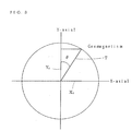
- the meridional direction is set to be 0°
- the clockwise rotating angle (orientation angle) ⁇ which defines the direction of the resultant vector T (representative of the direction of the magnetic sensor) of the x-axial magnetic field vector value X 1 and the y-axial magnetic field vector value Y 1 is obtained by the following expression.
- ⁇ tan -1 X 1 /Y 1
- the calculation of the orientation angle ⁇ is enabled by a calculating logic not using the correction parameter for the magnetic field vector values in the respective directions.
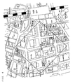
- map information display processing portion 8 will be described by way of example with reference to Figs. 4 to 6. It is assumed that a person using the portable terminal device now stands in a corner portion of Kogakuin University on Chuo-street leading to Shinjuku station and is facing North-East (so that the orientation angle ⁇ is 45°) as indicated in Fig. 4. Map information corresponding to the longitude and the latitude in question is read from the map information storing portion 7 in accordance with the position signal from the GPS receiving portion 2. Then, the map information in an area that matches the size of the visual display 91 (for example, 200 pixels x 200 pixels) with the present position P as its centre is sectioned and selected as indicated by a square outline in Fig. 4.
- the visual display 91 for example, 200 pixels x 200 pixels
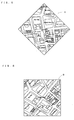
- the selected map information A (shown in Fig. 5) is the map information in an area corresponding to the display 91 lying at the orientation angle ⁇ , obtained by the orientation signal from the magnetic sensor 2, clockwise from magnetic north (refer to Fig. 4).
- the map information (Fig. 5) is displayed on the display 91, the map information A selected by the above display processing portion 8 is rotationally processed by the orientation angle ⁇ counterclockwise and displayed thus corrected as map information B (refer to Fig. 6).
- the map information B is a map in which the direction (forward direction) of the magnetic sensor 2 is always toward the upper side of the display 91.
- the display processing portion 8 conducts the same processing as the above-described processing and displays the map information with the forward direction always toward the upper side of the display. Successive processings by the map information display processing portion 8 are conducted at high speed in real time.
- the map information display processing portion 8 maintains the characters and the marks contained in the map information displayed on the display 91 at the original positional relation with respect to the upper side direction of the display without conducting any rotating process when the map information is rotationally processed on the basis of the orientation angle.
- Figure 6 shows an embodiment of the invention in which the street and building names of the map rotate with the map as the display (and portable telephone or unit) rotates but in which the position indicator words "PRESENT POSITION" move relative to the map detail so as to always remain parallel to the top of the display.
- the street names etc. could also rotate relative to the map so as to always remain parallel to the top of the display.
- the map characters and so on are rotated by the orientation angle without conducting the above processing and displayed.
- the position characters and the marks mentioned in a horizontal direction maintain a manner in which they are mentioned horizontally (i.e. parallel to the top edge of display) even in the case where the map information is rotationally displayed, likewise. As a result, the information of the position characters, etc., is readily visible.
- the destination may be inputted such as by using a keyboard of the portable terminal device.
- the shortest route to and the time required to reach the destination are calculated on the basis of the map information and then displayed on the visual display 91 of the position information display portion output through the voice output portion 92.
- the positional information of the GPS receiving portion and the orientation information of the magnetic sensor which have been received or measured are temporarily stored, a locus along which the portable terminal device has moved can be confirmed on the basis of the stored information later.
- a flux gate type magnetic sensor consisting of a sensor substrate in which a magnetic field detection coil substrate and an exciting coil substrate are laminated on the upper and lower surfaces of a sensor core, or a geomagnetic sensor using a hall element, a magnetic resistance element or the like is employed as the orientation detecting means used together with the GPS position detecting means, an accurate present position of a user can be displayed together with the map information on a display of a small portable terminal device, in particular, a portable telephone.
- the map information since the map information is subjected to rotary scrolling by the map information processing means on the basis of the orientation angle obtained from the magnetic field vector value provided by the magnetic sensor, the map information can be displayed in such a manner that the forward moving direction of the portable terminal device is always a predetermined specified direction within a plane of the display portion, so that the orientation cf the map information coincides with the forward direction and the user is not disorientated and can understand the orientation and position during movement.
- the positional information provided by the GPS is complemented by the orientation information provided by the geomagnetic sensor, the error accumulated by the integrating system can be permanently eliminated so as to provide a position display system of high precision.
Landscapes
- Engineering & Computer Science (AREA)
- Radar, Positioning & Navigation (AREA)
- Remote Sensing (AREA)
- Physics & Mathematics (AREA)
- General Physics & Mathematics (AREA)
- Automation & Control Theory (AREA)
- Theoretical Computer Science (AREA)
- Mathematical Physics (AREA)
- Computer Networks & Wireless Communication (AREA)
- Business, Economics & Management (AREA)
- Educational Administration (AREA)
- Educational Technology (AREA)
- Navigation (AREA)
- Traffic Control Systems (AREA)
- Position Fixing By Use Of Radio Waves (AREA)
- Telephonic Communication Services (AREA)
- Instructional Devices (AREA)
Applications Claiming Priority (2)
| Application Number | Priority Date | Filing Date | Title |
|---|---|---|---|
| JP2000104689A JP2001289646A (ja) | 2000-04-06 | 2000-04-06 | 位置情報表示システム |
| JP2000104689 | 2000-04-06 |
Publications (1)
| Publication Number | Publication Date |
|---|---|
| EP1148459A2 true EP1148459A2 (fr) | 2001-10-24 |
Family
ID=18618189
Family Applications (1)
| Application Number | Title | Priority Date | Filing Date |
|---|---|---|---|
| EP01303179A Withdrawn EP1148459A2 (fr) | 2000-04-06 | 2001-04-03 | Sytème d'affichage d'une information de position |
Country Status (6)
| Country | Link |
|---|---|
| US (1) | US20010029430A1 (fr) |
| EP (1) | EP1148459A2 (fr) |
| JP (1) | JP2001289646A (fr) |
| KR (1) | KR20010096464A (fr) |
| CN (1) | CN1316355A (fr) |
| TW (1) | TW503324B (fr) |
Cited By (3)
| Publication number | Priority date | Publication date | Assignee | Title |
|---|---|---|---|---|
| EP1568966A3 (fr) * | 2004-02-27 | 2007-02-21 | Samsung Electronics Co., Ltd. | Dispositif electronique portable et procédé pour changer le mode d'affichage de menu en fonction de rotation |
| EP1860404A1 (fr) * | 2006-05-22 | 2007-11-28 | THOMSON Licensing | Produit GPS |
| EP2277009A1 (fr) * | 2008-04-18 | 2011-01-26 | Sony Ericsson Mobile Communications AB | Contenu audio ameliore a realite augmentee |
Families Citing this family (37)
| Publication number | Priority date | Publication date | Assignee | Title |
|---|---|---|---|---|
| EP1314961B1 (fr) | 2001-11-22 | 2009-07-15 | Yamaha Corporation | Appareil électronique |
| KR100467839B1 (ko) * | 2002-03-09 | 2005-01-24 | 삼성전기주식회사 | 인쇄회로기판을 사용한 미약자계 감지용 센서 및 그 제조방법 |
| KR20020035059A (ko) * | 2002-04-04 | 2002-05-09 | 모인텔레콤(주) | 휴대단말기에서의 위치정보 표시 및 음성 안내 방법 과 밧데리 팩에 gps 모듈 및 부가 기능 악세사리 모듈 내장 방법 |
| CN100533504C (zh) * | 2002-09-18 | 2009-08-26 | 智点科技股份有限公司 | 高智能实时交通管理的装置及方法 |
| KR100485839B1 (ko) * | 2003-01-30 | 2005-04-28 | 삼성전자주식회사 | 특정장소의 방향 지시 기능을 갖는 개인 휴대형 장치 및그 제어방법 |
| KR20040098802A (ko) * | 2003-05-16 | 2004-11-26 | (주) 넥스모어시스템즈 | 개인 항법장치에 방향성을 주는 전자 나침반을 가진 gps 수신장치 |
| JP2004361918A (ja) | 2003-05-30 | 2004-12-24 | Lg Electronics Inc | 携帯端末機の特定地点方向コンパス表示装置及びその表示方法 |
| CN100353181C (zh) * | 2003-07-16 | 2007-12-05 | 明基电通股份有限公司 | 地磁辅助无线通信系统定位方法及无线通信定位系统 |
| KR100608723B1 (ko) * | 2003-11-27 | 2006-08-04 | 엘지전자 주식회사 | 휴대단말기의 상대방 위치 표시장치 및 방법 |
| KR100621401B1 (ko) * | 2004-03-31 | 2006-09-08 | 삼성전자주식회사 | 회전상태를 인식하여 저장된 정보를 탐색하는이동통신기기 및 그 방법 |
| JP4176040B2 (ja) | 2004-03-31 | 2008-11-05 | 京セラ株式会社 | 携帯通信端末とその地磁気センサの誤差補正方法 |
| WO2006008790A1 (fr) | 2004-07-15 | 2006-01-26 | C & N Inc | Dispositif de terminal mobile |
| KR100594549B1 (ko) * | 2004-07-20 | 2006-06-30 | 에스케이 텔레콤주식회사 | 인빌딩에서의 절대좌표를 이용한 측정 라우터의 표시장치및 좌표의 계측방법 |
| KR100683018B1 (ko) * | 2004-09-23 | 2007-02-15 | 정동근 | 시각장애인용 방향안내장치 |
| US20060094426A1 (en) * | 2004-10-29 | 2006-05-04 | Donaho Ralph W | Wireless communication system and method |
| JP4548102B2 (ja) * | 2004-11-25 | 2010-09-22 | ヤマハ株式会社 | 携帯端末機 |
| US20060133633A1 (en) * | 2004-12-17 | 2006-06-22 | Nokia Corporation | Mobile telephone with metal sensor |
| KR101121807B1 (ko) * | 2004-12-24 | 2012-03-19 | 주식회사 팬택 | 휴대 단말기를 이용한 물체의 3차원 좌표 측정 방법 및 이방법을 채택한 휴대 단말기 |
| KR101125630B1 (ko) * | 2005-03-03 | 2012-03-27 | 엘지전자 주식회사 | 이동통신 단말기의 자신의 위치 표시 장치 및 그 방법 |
| CN1941935B (zh) * | 2005-09-30 | 2011-10-05 | 乐金电子(中国)研究开发中心有限公司 | 移动通信终端及基于此的公共交通信息服务方法 |
| CN101149427B (zh) * | 2006-09-21 | 2010-08-25 | 环达电脑(上海)有限公司 | 全球定位系统的方向校正装置及方法 |
| US20080319654A1 (en) * | 2007-06-22 | 2008-12-25 | Sony Corporation | System and method for effectively implementing an electronic navigation device |
| KR100953079B1 (ko) * | 2007-11-09 | 2010-04-19 | 팅크웨어(주) | 지자기 센서를 이용한 맵 매칭 방법 및 내비게이션 시스템 |
| TWI467132B (zh) * | 2008-03-07 | 2015-01-01 | Mstar Semiconductor Inc | 導航裝置及使用其之導航方法 |
| JP5667974B2 (ja) * | 2008-06-30 | 2015-02-12 | トムトム インターナショナル ベスローテン フエンノートシャップ | 効率的な位置参照方法 |
| JP5223502B2 (ja) | 2008-07-03 | 2013-06-26 | ヤマハ株式会社 | 方位追従表示装置、方位追従表示方法および方位追従表示プログラム |
| CN101750080A (zh) * | 2008-12-04 | 2010-06-23 | 鸿富锦精密工业(深圳)有限公司 | 导航装置及其方法 |
| GB201100403D0 (en) | 2011-01-11 | 2011-02-23 | Totom Dev Germany Gmbh | An efficient location referencing method |
| US9214128B2 (en) * | 2011-08-10 | 2015-12-15 | Panasonic Intellectual Property Corporation Of America | Information display device |
| CN103575293B (zh) * | 2012-07-25 | 2016-08-10 | 华为终端有限公司 | 一种磁力计方向角校正方法及磁力计 |
| US9523576B2 (en) * | 2012-09-17 | 2016-12-20 | Xsens Holding B.V. | System and method for magnetic field data compression |
| CN103499707B (zh) * | 2013-09-29 | 2017-01-11 | 北京邮电大学 | 一种获取终端运动方向的方法及装置 |
| KR102164900B1 (ko) * | 2014-06-20 | 2020-10-13 | 삼성전자 주식회사 | 전자 장치 및 전자 장치의 위치 정보 측정 방법 |
| US9696428B2 (en) | 2014-06-20 | 2017-07-04 | Samsung Electronics Co., Ltd. | Electronic device and method for measuring position information of electronic device |
| US10931616B1 (en) | 2019-06-26 | 2021-02-23 | CallFire, Inc. | Location-based messaging system |
| EP4361783A4 (fr) | 2022-01-25 | 2025-01-15 | Samsung Electronics Co., Ltd. | Dispositif électronique présentant une unité d'affichage flexible |
| CN121421398A (zh) * | 2023-05-08 | 2026-01-30 | 杭州九阳小家电有限公司 | 基于显示终端的地图方位校正方法 |
-
2000
- 2000-04-06 JP JP2000104689A patent/JP2001289646A/ja active Pending
- 2000-05-29 TW TW089110426A patent/TW503324B/zh active
- 2000-08-24 KR KR1020000049143A patent/KR20010096464A/ko not_active Withdrawn
- 2000-11-30 US US09/728,013 patent/US20010029430A1/en not_active Abandoned
-
2001
- 2001-04-03 EP EP01303179A patent/EP1148459A2/fr not_active Withdrawn
- 2001-04-06 CN CN01109755A patent/CN1316355A/zh active Pending
Cited By (4)
| Publication number | Priority date | Publication date | Assignee | Title |
|---|---|---|---|---|
| EP1568966A3 (fr) * | 2004-02-27 | 2007-02-21 | Samsung Electronics Co., Ltd. | Dispositif electronique portable et procédé pour changer le mode d'affichage de menu en fonction de rotation |
| US7486323B2 (en) | 2004-02-27 | 2009-02-03 | Samsung Electronics Co., Ltd. | Portable electronic device for changing menu display state according to rotating degree and method thereof |
| EP1860404A1 (fr) * | 2006-05-22 | 2007-11-28 | THOMSON Licensing | Produit GPS |
| EP2277009A1 (fr) * | 2008-04-18 | 2011-01-26 | Sony Ericsson Mobile Communications AB | Contenu audio ameliore a realite augmentee |
Also Published As
| Publication number | Publication date |
|---|---|
| US20010029430A1 (en) | 2001-10-11 |
| CN1316355A (zh) | 2001-10-10 |
| JP2001289646A (ja) | 2001-10-19 |
| TW503324B (en) | 2002-09-21 |
| KR20010096464A (ko) | 2001-11-07 |
Similar Documents
| Publication | Publication Date | Title |
|---|---|---|
| EP1148459A2 (fr) | Sytème d'affichage d'une information de position | |
| JPH10185600A (ja) | 車両位置補正装置 | |
| JPH05113342A (ja) | ナビゲーシヨン装置 | |
| JP2783924B2 (ja) | 車両位置検出装置 | |
| JP3362976B2 (ja) | ナビゲーション装置 | |
| JPH02212713A (ja) | 移動体用ナビゲーション装置 | |
| JP3239440B2 (ja) | ナビゲーション装置 | |
| JPH083524B2 (ja) | Gps航法装置 | |
| EP0601712A1 (fr) | Système de navigation | |
| JP3251705B2 (ja) | 車両位置修正方式 | |
| JPH0666920A (ja) | 3次元位置測定装置及び方法 | |
| JP3435257B2 (ja) | マップマッチング方法 | |
| JP2001091270A (ja) | 電子方位計付携帯型ナビゲーション装置、及び目的地方向検出方法 | |
| JPH04370711A (ja) | 車両位置測定方法 | |
| JP3008813B2 (ja) | 方位出力装置 | |
| JPH06281721A (ja) | ナビゲーション装置 | |
| KR19990055652A (ko) | 차량위치 오차 보정장치 및 그 제어방법 | |
| JP4007924B2 (ja) | 携帯ナビゲーション装置 | |
| JP2945006B2 (ja) | Gps航法装置 | |
| JP2752563B2 (ja) | 地図画面の表示装置 | |
| JP2661904B2 (ja) | Gps航法装置 | |
| JPH0526681A (ja) | ナビゲーシヨン装置 | |
| JPH0942982A (ja) | 車載用ナビゲーション装置 | |
| JPH0540161A (ja) | 航法装置 | |
| HK1040674A (en) | Positional information display system |
Legal Events
| Date | Code | Title | Description |
|---|---|---|---|
| PUAI | Public reference made under article 153(3) epc to a published international application that has entered the european phase |
Free format text: ORIGINAL CODE: 0009012 |
|
| AK | Designated contracting states |
Kind code of ref document: A2 Designated state(s): AT BE CH CY DE DK ES FI FR GB GR IE IT LI LU MC NL PT SE TR |
|
| AX | Request for extension of the european patent |
Free format text: AL;LT;LV;MK;RO;SI |
|
| STAA | Information on the status of an ep patent application or granted ep patent |
Free format text: STATUS: THE APPLICATION HAS BEEN WITHDRAWN |
|
| 18W | Application withdrawn |
Withdrawal date: 20021129 |