EP1148759A1 - Gehäuse für audiogeräte - Google Patents
Gehäuse für audiogeräte Download PDFInfo
- Publication number
- EP1148759A1 EP1148759A1 EP01108553A EP01108553A EP1148759A1 EP 1148759 A1 EP1148759 A1 EP 1148759A1 EP 01108553 A EP01108553 A EP 01108553A EP 01108553 A EP01108553 A EP 01108553A EP 1148759 A1 EP1148759 A1 EP 1148759A1
- Authority
- EP
- European Patent Office
- Prior art keywords
- cabinet
- loudspeaker
- devices
- main cabinet
- loudspeakers
- Prior art date
- Legal status (The legal status is an assumption and is not a legal conclusion. Google has not performed a legal analysis and makes no representation as to the accuracy of the status listed.)
- Granted
Links
Images


Classifications
-
- H—ELECTRICITY
- H04—ELECTRIC COMMUNICATION TECHNIQUE
- H04R—LOUDSPEAKERS, MICROPHONES, GRAMOPHONE PICK-UPS OR LIKE ACOUSTIC ELECTROMECHANICAL TRANSDUCERS; ELECTRIC HEARING AIDS; PUBLIC ADDRESS SYSTEMS
- H04R5/00—Stereophonic arrangements
- H04R5/02—Spatial or constructional arrangements of loudspeakers
Definitions
- the present invention is related to a cabinet for consumer electronic devices equipped with loudspeakers. Examples for such devices are audio equipment like CD players, tape recorders, radios, and television receivers. In particular, the invention is related to devices where the loudspeakers form an integral part of it.
- the cabinet is formed as an integral part for housing electronic and mechanical components as it is shown in Figs. 1a and 1b.
- the electrical components comprise among others the power supply and signal processing circuits.
- the mechanical components may be a tape recorder and/or a CD player.
- the housing acts as a structuring element apt for arranging all required components for the device.
- the housing protects the user from hazardous electrical shocks and the components from damages due to external influences like dirt or moisture.
- the cabinet allows designing the device, i.e. the shape, size and looking. For all this reasons the cabinet is a very important part of the device, sometimes decisive for its commercial success.
- the cabinet is made out of plastic by injection moulding.
- Known cabinets enclose all components especially the loudspeakers.
- For marketing purposes it is frequently required to have different models of different design and size for different markets. It is therefore necessary to manufacture different types of cabinets for devices having different types of loudspeakers or different design of the loudspeaker boxes.
- the cabinet comprises a main cabinet for housing electrical and mechanical components of the electronic device and further comprises a cabinet for a loudspeaker being separate from the main cabinet and connected to the outside of the main cabinet in an non-detachable manner.
- the present invention allows to design audio devices with different look without requiring completely individual cabinets. Rather the invention suggests to use a standardized main cabinet to take advantage of a more cost efficient manufacturing.
- a vibration damping means is arranged between the main cabinet and the loudspeaker cabinet.
- the vibration damping means improve the sound quality but also prevent dust or moisture from penetrating into the loudspeaker cabinet.
- the main cabinet is provided with urging means pressing the loudspeaker cabinet against the main cabinet to secure a tight seat of the loudspeaker cabinet on the main cabinet.
- Fig. 1a shows a portable audio device 1 of a conventional type having for example a radio receiver, a tape recorder and a CD player.
- the components are contained in a cabinet 2 made out of injection moulded plastic.
- the device 1 is equipped with two sets of loudspeakers 3a, 3b on the left and on the right side of the cabinet 2 for stereo representation of the sound.
- Fig. 1a and 1b it can be seen that the device shown in Fig. 1b the loudspeaker cabinets are larger compared to the device shown in Fig. 1a.
- the design shown in Fig. 1b gives the user the impression that this device is more powerful than the one shown in Fig.
- a portable audio device 1 according to the present invention is shown in a front view.
- the cabinet of this device comprises a main cabinet 4 which is manufactured in a conventional way, e.g. by injection moulding of plastic material.
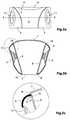
- the main cabinet 4 incorporates a front wall 6 and a back wall 7 (Fig. 2b).
- the front and the back walls are connected by sidewalls 8 (Fig. 2b).
- Attached to the main cabinet 4 there are two loudspeaker cabinets 9 on each side of the main cabinet 4. It is important to note that the loudspeaker cabinets 9 are separate parts from the main cabinet and are attached to the latter by clipping means, screws or any other technique that is known in the prior art for connecting plastic form parts.
- Each loudspeaker cabinet 9 houses a loudspeaker 11 for the reproduction of audio signals reproduced by a CD player, tape recorder or radio receiver incorporated in the main cabinet 4.
- a CD door 12 is shown in Fig. 2a.
- the electrical connection between the loudspeakers 11 and the signal processing and amplifying circuits are made by conventional plug connections or simply by wires penetrating the sidewalls 8 of the main cabinet 4.
- Fig. 2c shows an enlarged detail of Fig. 2b and in particular, the contact area between the loudspeaker cabinet 9 and the main cabinet 4.
- a vibration damping material 13 e.g. a rubber gasket.
- the damping material 13 prevents the transmission of vibrations from the loudspeakers to the main cabinet.
- the rubber gasket 13 has a circular section and is accommodated in a half circular groove 14 in the main cabinet 4.
- the front end 16 of the loudspeaker cabinet 9 is also provided with another half circular groove 17 so that the rubber gasket 13 is securely held in the grooves 14 and 17.
- Protrusions 18 prolong the front wall 6 and the back wall 7 of the main cabinet 4.
- the loudspeaker cabinet closely fits between one protrusion 18 of the front wall 6 and back wall 7 as can be seen in Fig. 2b. Therefore, there is no visible gap between the main cabinet 4 and the loudspeaker cabinet 9.
- the securing means connecting the main cabinet 4 and the loudspeaker cabinet 9 are not shown in the drawing and are of conventional type like screws, clips, glue, etc. The securing means are arranged such that it is not possible for the user to detach the loudspeaker cabinet 9 from the main cabinet 4.
- the cross section of the rubber gasket can have a different shape as shown in Fig. 2c.
- the rubber gasket 13 can be mounted or not in a particular type of cabinet.
- the vibration damping rubber gasket 13 reduces the transfer of vibrations generated by the loudspeakers to the main cabinet. Simultaneous the rubber gasket 13 improves the sound quality as such due to its capability to dampen parasitic vibrations.
- Figs. 3a and Fig. 3b display in a different scale another type of a portable audio device according to the present invention.
- the main cabinet 4 of the first and second embodiment of the invention should have the same size and shape whereas the loudspeaker cabinets are quite different.
- each loudspeaker cabinet 9 houses one additional loudspeaker 19. Therefore, the second embodiment shown in Fig. 3a and 3b exhibits a completely different outlook apart from the different sound characteristics.
Landscapes
- Physics & Mathematics (AREA)
- Engineering & Computer Science (AREA)
- Acoustics & Sound (AREA)
- Signal Processing (AREA)
- Details Of Audible-Bandwidth Transducers (AREA)
Priority Applications (1)
| Application Number | Priority Date | Filing Date | Title |
|---|---|---|---|
| EP01108553A EP1148759B1 (de) | 2000-04-18 | 2001-04-05 | Gehäuse für audiogeräte |
Applications Claiming Priority (3)
| Application Number | Priority Date | Filing Date | Title |
|---|---|---|---|
| EP00108438A EP1148758A1 (de) | 2000-04-18 | 2000-04-18 | Gehäuse für Audiogeräte |
| EP00108438 | 2000-04-18 | ||
| EP01108553A EP1148759B1 (de) | 2000-04-18 | 2001-04-05 | Gehäuse für audiogeräte |
Publications (2)
| Publication Number | Publication Date |
|---|---|
| EP1148759A1 true EP1148759A1 (de) | 2001-10-24 |
| EP1148759B1 EP1148759B1 (de) | 2012-09-19 |
Family
ID=26070838
Family Applications (1)
| Application Number | Title | Priority Date | Filing Date |
|---|---|---|---|
| EP01108553A Expired - Lifetime EP1148759B1 (de) | 2000-04-18 | 2001-04-05 | Gehäuse für audiogeräte |
Country Status (1)
| Country | Link |
|---|---|
| EP (1) | EP1148759B1 (de) |
Cited By (1)
| Publication number | Priority date | Publication date | Assignee | Title |
|---|---|---|---|---|
| WO2008077535A1 (de) * | 2006-12-21 | 2008-07-03 | Xounts Ag | Anordnung mit durch schwingungen betriebenen klangkörpern |
Citations (3)
| Publication number | Priority date | Publication date | Assignee | Title |
|---|---|---|---|---|
| EP0114951A1 (de) * | 1982-12-23 | 1984-08-08 | Walter Schupbach | Stereophonisches Lautsprechergehäuse |
| EP0492919A2 (de) * | 1990-12-22 | 1992-07-01 | Sony Corporation | Fernsehempfänger-Lautsprechereinrichtung |
| GB2303485A (en) * | 1995-07-19 | 1997-02-19 | Peter Stewart Younger | Detachable/portable stereo unit |
Family Cites Families (2)
| Publication number | Priority date | Publication date | Assignee | Title |
|---|---|---|---|---|
| DE1076184B (de) * | 1958-09-30 | 1960-02-25 | Blaupunkt Werke Gmbh | Truhe fuer Rundfunk- und Fernsehempfang |
| JPH0828107B2 (ja) * | 1987-09-04 | 1996-03-21 | 松下電器産業株式会社 | 音響装置 |
-
2001
- 2001-04-05 EP EP01108553A patent/EP1148759B1/de not_active Expired - Lifetime
Patent Citations (3)
| Publication number | Priority date | Publication date | Assignee | Title |
|---|---|---|---|---|
| EP0114951A1 (de) * | 1982-12-23 | 1984-08-08 | Walter Schupbach | Stereophonisches Lautsprechergehäuse |
| EP0492919A2 (de) * | 1990-12-22 | 1992-07-01 | Sony Corporation | Fernsehempfänger-Lautsprechereinrichtung |
| GB2303485A (en) * | 1995-07-19 | 1997-02-19 | Peter Stewart Younger | Detachable/portable stereo unit |
Cited By (1)
| Publication number | Priority date | Publication date | Assignee | Title |
|---|---|---|---|---|
| WO2008077535A1 (de) * | 2006-12-21 | 2008-07-03 | Xounts Ag | Anordnung mit durch schwingungen betriebenen klangkörpern |
Also Published As
| Publication number | Publication date |
|---|---|
| EP1148759B1 (de) | 2012-09-19 |
Similar Documents
| Publication | Publication Date | Title |
|---|---|---|
| US7496207B2 (en) | Cabinet for audio devices | |
| JP3151380U (ja) | スピーカー構造 | |
| US7221772B2 (en) | Electronic device comprising a loudspeaker unit | |
| KR20140145068A (ko) | 측면 방사형 스피커 장치를 구비하는 전자 장치 | |
| EP1148759B1 (de) | Gehäuse für audiogeräte | |
| WO2008021695A2 (en) | Multi-channel speaker system | |
| US20030077945A1 (en) | Connector for speaker | |
| EP1207717A1 (de) | Elektronische Vorrichtung mit variabler Schallkammer | |
| US7911800B2 (en) | Housing for electrical apparatus | |
| US20070036387A1 (en) | Speaker with reduced height | |
| US20050271218A1 (en) | Palm type dolby decoding earphone device | |
| KR100708088B1 (ko) | 전자제품의 전자파 차폐용 접지장치 | |
| KR200239036Y1 (ko) | 디스플레이장치의마이크장착장치 | |
| KR200158240Y1 (ko) | 스피커 유닛의 진동 방지장치 | |
| JPS63167598A (ja) | オ−デイオ機器 | |
| KR200340360Y1 (ko) | 전자제품용 잭 어댑터 | |
| KR200149726Y1 (ko) | 스피커 시스템 | |
| KR200397255Y1 (ko) | Mp3 플레이어 | |
| EP1939884B1 (de) | Akustische vorrichtung in einem fahrzeug | |
| KR19990013934U (ko) | 스피커 유닛용 보호 장식망의 조립구조 | |
| KR19990017105U (ko) | 스피커 유닛과 받침대의 결합구조 | |
| KR200265686Y1 (ko) | 착탈 가능한 텔레비젼 입력단자판 | |
| KR20060016295A (ko) | 진동 방지를 위한 외장형 스피커 시스템 | |
| US20060098152A1 (en) | Display apparatus | |
| KR20050012972A (ko) | 튜너 접지구조 |
Legal Events
| Date | Code | Title | Description |
|---|---|---|---|
| PUAI | Public reference made under article 153(3) epc to a published international application that has entered the european phase |
Free format text: ORIGINAL CODE: 0009012 |
|
| AK | Designated contracting states |
Kind code of ref document: A1 Designated state(s): AT BE CH CY DE DK ES FI FR GB GR IE IT LI LU MC NL PT SE TR Kind code of ref document: A1 Designated state(s): DE ES FR GB IT |
|
| AX | Request for extension of the european patent |
Free format text: AL;LT;LV;MK;RO;SI |
|
| 17P | Request for examination filed |
Effective date: 20020321 |
|
| AKX | Designation fees paid |
Free format text: DE ES FR GB IT |
|
| 17Q | First examination report despatched |
Effective date: 20080227 |
|
| GRAP | Despatch of communication of intention to grant a patent |
Free format text: ORIGINAL CODE: EPIDOSNIGR1 |
|
| GRAS | Grant fee paid |
Free format text: ORIGINAL CODE: EPIDOSNIGR3 |
|
| GRAA | (expected) grant |
Free format text: ORIGINAL CODE: 0009210 |
|
| AK | Designated contracting states |
Kind code of ref document: B1 Designated state(s): DE ES FR GB IT |
|
| REG | Reference to a national code |
Ref country code: GB Ref legal event code: FG4D |
|
| REG | Reference to a national code |
Ref country code: DE Ref legal event code: R096 Ref document number: 60147118 Country of ref document: DE Effective date: 20121115 |
|
| PG25 | Lapsed in a contracting state [announced via postgrant information from national office to epo] |
Ref country code: ES Free format text: LAPSE BECAUSE OF FAILURE TO SUBMIT A TRANSLATION OF THE DESCRIPTION OR TO PAY THE FEE WITHIN THE PRESCRIBED TIME-LIMIT Effective date: 20121230 |
|
| PLBE | No opposition filed within time limit |
Free format text: ORIGINAL CODE: 0009261 |
|
| STAA | Information on the status of an ep patent application or granted ep patent |
Free format text: STATUS: NO OPPOSITION FILED WITHIN TIME LIMIT |
|
| 26N | No opposition filed |
Effective date: 20130620 |
|
| PG25 | Lapsed in a contracting state [announced via postgrant information from national office to epo] |
Ref country code: IT Free format text: LAPSE BECAUSE OF FAILURE TO SUBMIT A TRANSLATION OF THE DESCRIPTION OR TO PAY THE FEE WITHIN THE PRESCRIBED TIME-LIMIT Effective date: 20120919 |
|
| REG | Reference to a national code |
Ref country code: DE Ref legal event code: R097 Ref document number: 60147118 Country of ref document: DE Effective date: 20130620 |
|
| GBPC | Gb: european patent ceased through non-payment of renewal fee |
Effective date: 20130405 |
|
| PG25 | Lapsed in a contracting state [announced via postgrant information from national office to epo] |
Ref country code: DE Free format text: LAPSE BECAUSE OF NON-PAYMENT OF DUE FEES Effective date: 20131101 Ref country code: GB Free format text: LAPSE BECAUSE OF NON-PAYMENT OF DUE FEES Effective date: 20130405 |
|
| REG | Reference to a national code |
Ref country code: FR Ref legal event code: ST Effective date: 20131231 |
|
| REG | Reference to a national code |
Ref country code: DE Ref legal event code: R119 Ref document number: 60147118 Country of ref document: DE Effective date: 20131101 |
|
| PG25 | Lapsed in a contracting state [announced via postgrant information from national office to epo] |
Ref country code: FR Free format text: LAPSE BECAUSE OF NON-PAYMENT OF DUE FEES Effective date: 20130430 |