EP1148963B1 - Spanabhebendes werkzeug - Google Patents
Spanabhebendes werkzeug Download PDFInfo
- Publication number
- EP1148963B1 EP1148963B1 EP00908995A EP00908995A EP1148963B1 EP 1148963 B1 EP1148963 B1 EP 1148963B1 EP 00908995 A EP00908995 A EP 00908995A EP 00908995 A EP00908995 A EP 00908995A EP 1148963 B1 EP1148963 B1 EP 1148963B1
- Authority
- EP
- European Patent Office
- Prior art keywords
- cutting
- chip breaker
- tool according
- cutting tool
- chip
- Prior art date
- Legal status (The legal status is an assumption and is not a legal conclusion. Google has not performed a legal analysis and makes no representation as to the accuracy of the status listed.)
- Expired - Lifetime
Links
- 238000005520 cutting process Methods 0.000 title claims abstract description 105
- 239000000463 material Substances 0.000 claims abstract description 14
- 239000002131 composite material Substances 0.000 claims description 7
- 230000007704 transition Effects 0.000 claims description 5
- 238000005553 drilling Methods 0.000 claims description 3
- 238000003801 milling Methods 0.000 claims description 3
- 150000001875 compounds Chemical class 0.000 claims 3
- 229910003460 diamond Inorganic materials 0.000 abstract description 3
- 239000010432 diamond Substances 0.000 abstract description 3
- 229910052751 metal Inorganic materials 0.000 description 3
- 239000002184 metal Substances 0.000 description 3
- 241000985128 Cladium mariscus Species 0.000 description 2
- 230000015572 biosynthetic process Effects 0.000 description 2
- 238000003754 machining Methods 0.000 description 2
- 229910052582 BN Inorganic materials 0.000 description 1
- PZNSFCLAULLKQX-UHFFFAOYSA-N Boron nitride Chemical compound N#B PZNSFCLAULLKQX-UHFFFAOYSA-N 0.000 description 1
- RYGMFSIKBFXOCR-UHFFFAOYSA-N Copper Chemical compound [Cu] RYGMFSIKBFXOCR-UHFFFAOYSA-N 0.000 description 1
- 229910000997 High-speed steel Inorganic materials 0.000 description 1
- 208000027418 Wounds and injury Diseases 0.000 description 1
- 238000004026 adhesive bonding Methods 0.000 description 1
- 229910052782 aluminium Inorganic materials 0.000 description 1
- XAGFODPZIPBFFR-UHFFFAOYSA-N aluminium Chemical compound [Al] XAGFODPZIPBFFR-UHFFFAOYSA-N 0.000 description 1
- 230000006835 compression Effects 0.000 description 1
- 238000007906 compression Methods 0.000 description 1
- 229910052802 copper Inorganic materials 0.000 description 1
- 239000010949 copper Substances 0.000 description 1
- 230000006378 damage Effects 0.000 description 1
- 230000001419 dependent effect Effects 0.000 description 1
- 230000002349 favourable effect Effects 0.000 description 1
- 208000014674 injury Diseases 0.000 description 1
- 230000010354 integration Effects 0.000 description 1
- 238000004519 manufacturing process Methods 0.000 description 1
- 239000007769 metal material Substances 0.000 description 1
- 238000000034 method Methods 0.000 description 1
- 229920003023 plastic Polymers 0.000 description 1
- 239000004033 plastic Substances 0.000 description 1
- 238000007493 shaping process Methods 0.000 description 1
- 238000005245 sintering Methods 0.000 description 1
- 238000005476 soldering Methods 0.000 description 1
Images
Classifications
-
- B—PERFORMING OPERATIONS; TRANSPORTING
- B23—MACHINE TOOLS; METAL-WORKING NOT OTHERWISE PROVIDED FOR
- B23B—TURNING; BORING
- B23B51/00—Tools for drilling machines
- B23B51/009—Stepped drills
-
- B—PERFORMING OPERATIONS; TRANSPORTING
- B23—MACHINE TOOLS; METAL-WORKING NOT OTHERWISE PROVIDED FOR
- B23B—TURNING; BORING
- B23B2251/00—Details of tools for drilling machines
- B23B2251/48—Chip breakers
Definitions
- the invention relates to a cutting tool for drilling, Reaming, countersinking, milling, sawing and turning with at least one Cutting edge and with at least one chip breaker on the cutting edge.
- Machining results primarily from long-chipping Materials such as Aluminum, copper, plastics etc. Problems with chip removal. With these materials you can Chips reach uncontrollable lengths, get caught, that Make chip flow more difficult and also entail the risk of injury.
- Chip breakers are inherently on cutting tools such as milling Known turning tools. It is also known to the Cutting, drilling, sinking and reaming tools, incorporating chip breakers, to achieve the formation of short, manageable chips.
- CH-A-307 714 is for example a cutting tool with a cutting edge made of hard metal and a top plate made of high-speed steel placed on this known, both the cutting and cover plate, are soldered.
- the cover plate is set back slightly from the cutting edge and forms a chip breaker with its end face.
- the object on which the invention is based is now a way to create chip breakers or chip breakers on the tool cutting edges made of difficult to process cutting materials such as. To install PKD economically so that a Favorable chip shape for the material to be processed arises.
- a cutting tool thus comprises at least one cutting edge and at least one chip breaker the cutting edge.
- a composite plate on the tool body attached from chip breaker part and cutting part, whereby the composite panel is designed as a sandwich panel and one Cutting part with support (carrier) includes.
- the cutting part is made of a cutting material made of PCD or CBN.
- the chipbreaker part is on the cutting part and the cutting part on the Sintered overlay.
- the tool according to the invention is characterized in that the chip breaker not directly as usual in the hard Cutting material is incorporated, but in a separate chip breaker part, which is firmly connected to the cutting part.
- One advantage of the tool according to the invention is a minor one Number of parts and thus high integration of the tool, which means the number of manufacturing steps is low and the mechanical Strength and security are high.
- Chip breaker or chip breaker function in one area, in which the required chip breaker or chip breaker geometry can be attached economically.
- the chip flow can be achieved by designing the chip breaker accordingly easily adapt to the respective requirements of the material. This also applies to areas that are difficult to machine the tool cutting edge, since the composite panel is already in place before fastening on the basic tool body or the basic tool body even be provided with the chip breaker beforehand can.
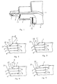
- the step tool with chip breaker shown in Fig. 1 shows a possible embodiment of the chip breaker 11 on a tool made of hard metal with polycrystalline diamond cutting edge 2.
- This economically producible chip breaker 11 is before fastening that of chip breaker part 1, cutting part 2 and support 3 cutting unit made of hard metal on the base body 4, incorporated into the chip breaker plate 1. It is not required, material made from the ultra-hard cutting material to remove.
- the chip breaker 11 or the chip breaker are in the overlying more easily editable material 1 incorporated.
- Fig. 2 shows the cutting area with cutting body 2, the Chipbreaker part 1 and the edition 3, which together (with the incorporated chip breaker 11), i.e. as a sandwich plate, in Tool body 4 are attached.
- connection between the individual components of the chipbreaker plate 1, cutting part 2 and pad 3 to a composite plate takes place by sintering on the surfaces 5.
- Chip breaker part 1, cutting part 2 and support 3 Composite plate or cutting unit with the finished one Chip breaker 11 or chip breaker is on the tool body 4 preferably by soldering, gluing to the surfaces 6 or attached by screws.
- the chip breaker surface is used for the compressed compression and shaping of the chip 11 from the rake face 22 by a radius R with subsequent angle ⁇ formed (Fig. 2).
- this angle ⁇ in the range from 0 ° to 30 °, preferably 10 ° to 20 °.
- the chip breaker surface 11 is formed by a radius R.
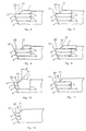
- FIG. 4 to 9 Further advantageous designs of the chip breaker are shown in Fig. 4 to 9 shown.
- the chipbreaker part 1 is open attached to the tool body 4.
- the cutting part 2 with the pad 3 is attached to the chip breaker part 1.
- the hard metal material of the tool body 4 in the cutting area been ground to a chip breaker part.
- a slot has been cut or eroded, in which the cutting part 2 is soldered to the carrier (B).
- the tool base body 4 shown in FIG. 12 is again trained as a chip breaker.
- the cutting part 2, 3 is on it attached.
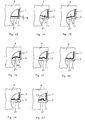
- FIG. 13 to 19 Another possible advantageous embodiment of the chipbreaker in Cutting direction are shown in Fig. 13 to 19.
- this runs parallel to the cutting edge at a distance a of preferably 0.5 mm to 1.2 mm.
- FIGS. 14 and 15 leave directional influence the chip flow by size and direction of the Angle ⁇ and ⁇ , between chip breaker 11 and cutting edge 21.
- FIGS. 13 to 16 11 Further embodiments of the chip breaker shown in FIGS. 13 to 16 11 also allow you to influence the Shape of the chips.
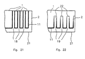
- guide grooves 18 molded into the chipbreaker plate 1 with a flat trapezoidal cross section. These guide grooves are continuous in the chip breaker plate 1 and the subsequent flute incorporated.
- the embodiment shown in FIG. 22 has the guide grooves 19 only in the chip breaker plate 1.
Landscapes
- Engineering & Computer Science (AREA)
- Mechanical Engineering (AREA)
- Milling Processes (AREA)
- Cutting Tools, Boring Holders, And Turrets (AREA)
- Drilling Tools (AREA)
- Auxiliary Devices For Machine Tools (AREA)
Description
- Fig. 1
- eine Teilansicht eines Stufenwerkzeuges mit Bohrspitze, jeweils mit Spanbrecher,
- Fig. 2
- eine Seitenansicht eines Spanbrecher-Schneidenbereiches mit Übergangsradius zur daran anschließenden schrägen Spanbrecherfläche,
- Fig. 3
- eine Seitenansicht eines Spanbrecher-Schneidenbereiches mit radiusförmiger Spanbrecherfläche,
- Fig. 4
- eine Seitenansicht eines Spanbrecher-Schneidenbereiches mit gerader, unter einem Winkel verlaufender Spanbrecherfläche,
- Fig. 5
- eine Seitenansicht eines Spanbrecher-Schneidenbereiches mit einem Spanbrecherteil, welches das Scheidenteil überlappt,
- Fig. 6
- eine Seitenansicht eines Spanbrecher-Schneidenbereiches mit mehreren aneinanderliegenden konkaven Spanbrecherflächen,
- Fig. 7
- eine Seitenansicht eines Spanbrecher-Schneidenbereiches mit mehreren aneinanderliegenden, konvexen Spanbrecherflächen,
- Fig. 8 und 9
- Seitenansichten eines Spanbrecher-Schneidenbereiches mit treppenförmigen Spanbrecherflächen,
- Fig. 10
- eine Seitenansicht eines Spanbrecherschneidenbereichs ähnlich Fig. 2, mit auf dem Werkzeuggrundkörper befestigtem Spanbrecherteil und auf diesem befestigtem Schneidenteil,
- Fig. 11
- eine Seitenansicht eines Spanbrecher-Schneidenbereichs ähnlich Fig. 3, mit in einem Schlitz des Werkzeuggrundkörpers aufgenommenem Schneidenteil,
- Fig. 12
- eine Seitenansicht eines Spanbrecherschneidenbereichs ähnlich Fig. 3. , mit am Werkzeuggrundkörper befestigtem Schneidenteil,
- Fig. 13 bis 15
- Teilansichten eines Spanbrecher-Schneidenbereiches mit parallel zur Schneide bzw. unter einem Winkel zur Schneide verlaufenden Spanbrecherflächen,
- Fig. 16 bis 18
- Teilansichten eines Spanbrecher-Schneidenbereiches mit bogenförmig verlaufenden Spanbrecherflächen,
- Fig. 19
- eine Teilansicht eines Spanbrecher-Schneidenbereiches mit trapezförmigen Spanbrecherflächen,
- Fig. 20
- eine Teilansicht eines Spanbrecher-Schneidenbereiches mit einem taschenförmig ausgearbeiteten Spanbrecher,
- Fig. 21
- eine Teilansicht eines Spanbrecher-Schneidenbereiches mit Spanleitrillen, welche durch das Spanbrecherteil und die anschließende weiterführende Spannut führen, und
- Fig. 22
- eine Teilansicht eines Spanbrecher-Schneidenbereiches mit Spanleitrillen, welche kürzer als das Spanbrecherteil ausgeführt sind.
Claims (22)
- Spanabhebendes Werkzeug zum Bohren, Reiben, Senken, Fräsen, Sägen und Drehen mit mindestens einer Schneide und mit wenigstens einem Spanbrecher an der Schneide,
dadurch gekennzeichnet, daß
auf dem Werkzeuggrundkörper (4) eine als Sandwichplatte ausgebildete Verbundplatte aus Spanbrecherteil (1) und Schneidenteil (2) mit Auflage (3) befestigt ist,
der Schneidenteil (2) aus einem Schneidstoff aus PKD oder CBN ist und
der Spanbrecherteil (1) auf den Schneidenteil (2) und der Schneidenteil (2) auf die Auflage (3) aufgesintert ist. - Spanabhebendes Werkzeug nach Anspruch 1, dadurch gekennzeichnet, daß der Schneidenteil (2) in einem Schlitz des Werkzeuggrundkörpers befestigt ist.
- Spanabhebendes Werkzeug nach Anspruch 1 oder 2, dadurch gekennzeichnet, daß der Übergang zwischen Schneidenteil (2) und Spanbrecherteil (1) durch einen Radius (R) gebildet wird.
- Spanabhebendes Werkzeug nach einem der vorhergehenden Ansprüche, dadurch gekennzeichnet, daß der Übergang zwischen Schneidenteil (2) und Spanbrecherteil (1) durch einen Winkel δ gebildet wird.
- Spanabhebendes Werkzeug nach einem der vorhergehenden Ansprüche, dadurch gekennzeichnet, daß der Übergang zwischen Schneidenteil (2) und Spanbrecherteil (1) durch einen Übergangsradius (R) mit einem daran anschließenden Winkel δ gebildet wird.
- Spanabhebendes Werkzeug nach einem der vorhergehenden Ansprüche, dadurch gekennzeichnet, daß die Spanbrecherfläche aus mehreren aneinanderliegenden, konkaven Flächen (13) gebildet wird.
- Spanabhebendes Werkzeug nach einem der vorhergehenden Ansprüche, dadurch gekennzeichnet, daß die Spanbrecherfläche aus mehrereren aneinanderliegenden, konvexen Flächen (14) besteht.
- Spanabhebendes Werkzeug nach einem der vorhergehenden Ansprüche, dadurch gekennzeichnet, daß die Spanbrecherfläche aus treppenförmig angeordneten Einzelflächen (15, 16) besteht.
- Spanabhebendes Werkzeug nach einem der vorhergehenden Ansprüche, dadurch gekennzeichnet, daß die aus Spanbrecherteil (1), Schneidenteil (2) und Unterlage (3) bestehende Verbundplatte auf den Werkzeuggrundkörper (4) aufgelötet ist.
- Spanabhebendes Werkzeug nach einem der vorhergehenden Ansprüche, dadurch gekennzeichnet, daß die mit dem Spanbrecher (11) versehene Verbundplatte auf den Werkzeuggrundkörper (4) aufgeklebt ist.
- Spanabhebendes Werkzeug nach einem der vorhergehenden Ansprüche, dadurch gekennzeichnet, daß die mit dem Spanbrecher (11) versehene Verbundplatte auf den Werkzeuggrundkörper (4) aufgeschraubt ist.
- Spanabhebendes Werkzeug nach einem der vorhergehenden Ansprüche, dadurch gekennzeichnet, daß die mit dem Spanbrecher (11) versehene Verbundplatte auf den Werkzeuggrundkörper (4) geklemmt ist.
- Spanabhebendes Werkzeug nach einem der vorhergehenden Ansprüche, dadurch gekennzeichnet, daß der Spanbrecher (11) parallel zur Schneide (21) verläuft.
- Spanabhebendes Werkzeug nach einem der vorhergehenden Ansprüche, dadurch gekennzeichnet, daß der Spanbrecher (11) einen Winkel α oder β mit der Schneide (21) bildet.
- Spanabhebendes Werkzeug nach einem der vorhergehenden Ansprüche, dadurch gekennzeichnet, daß der Spanbrecher (11) bogenförmig oder teilweise bogenförmig ausgeführt ist.
- Spanabhebendes Werkzeug nach einem der vorhergehenden Ansprüche, dadurch gekennzeichnet, daß der Spanbrecher (11) mit wellenförmigen oder trapezförmigen Rillen ausgeführt ist.
- Spanabhebendes Werkzeug nach einem der vorhergehenden Ansprüche, dadurch gekennzeichnet, daß das Spanbrecherteil (1) das Schneidenteil (2) überragt.
- Spanabhebendes Werkzeug nach einem der vorhergehenden Ansprüche, dadurch gekennzeichnet, daß das Spanbrecherteil eine taschenförmige Aussparung (17) enthält.
- Spanabhebendes Werkzeug nach einem der vorhergehenden Ansprüche, dadurch gekennzeichnet, daß das Spanbrecherteil Spanleitrillen (18) enthält, die durchgängig in der Spannut des Werkzeuggrundkörpers weitergeführt sind.
- Spanabhebendes Werkzeug nach einem der vorhergehenden Ansprüche, dadurch gekennzeichnet, daß das Spanbrecherteil Spanleitrillen (19) enthält, die kürzer als das Spanbrecherteil (1) ausgeführt sind.
- Spanabhebendes Werkzeug nach einem der vorhergehenden Ansprüche, dadurch gekennzeichnet, daß das Werkzeug mindestens 2 Stufen mit verschiedenen Durchmessern aufweist.
- Spanabhebendes Werkzeug nach einem der vorhergehenden Ansprüche, dadurch gekennzeichnet, daß das Werkzeug eine eingesetzte Bohrerspitze hat.
Applications Claiming Priority (3)
| Application Number | Priority Date | Filing Date | Title |
|---|---|---|---|
| DE29901414U DE29901414U1 (de) | 1999-01-28 | 1999-01-28 | Spanabhebendes Werkzeug |
| DE29901414U | 1999-01-28 | ||
| PCT/DE2000/000358 WO2000044518A1 (de) | 1999-01-28 | 2000-01-27 | Spanabhebendes werkzeug |
Publications (2)
| Publication Number | Publication Date |
|---|---|
| EP1148963A1 EP1148963A1 (de) | 2001-10-31 |
| EP1148963B1 true EP1148963B1 (de) | 2003-04-09 |
Family
ID=8068559
Family Applications (1)
| Application Number | Title | Priority Date | Filing Date |
|---|---|---|---|
| EP00908995A Expired - Lifetime EP1148963B1 (de) | 1999-01-28 | 2000-01-27 | Spanabhebendes werkzeug |
Country Status (5)
| Country | Link |
|---|---|
| EP (1) | EP1148963B1 (de) |
| JP (1) | JP2002539957A (de) |
| AT (1) | ATE236751T1 (de) |
| DE (2) | DE29901414U1 (de) |
| WO (1) | WO2000044518A1 (de) |
Families Citing this family (18)
| Publication number | Priority date | Publication date | Assignee | Title |
|---|---|---|---|---|
| DE202005006613U1 (de) * | 2005-04-26 | 2005-07-07 | Ake Knebel Gmbh & Co. Kg | Kreissägeblatt |
| US7878738B2 (en) | 2005-05-21 | 2011-02-01 | Keenametal Inc. | Milling cutter and a cutting insert for a milling cutter |
| DE102005023532A1 (de) * | 2005-05-21 | 2006-11-23 | Kennametal Inc. | Schneideinsatz für ein Werkzeug, insbesondere für ein Fräswerkzeug |
| EP2414122B1 (de) | 2009-03-30 | 2013-05-08 | Gühring OHG | Drehangetriebenes mehrfasen-stufenwerkzeug |
| SE533679C2 (sv) * | 2009-04-07 | 2010-11-30 | Sandvik Intellectual Property | Solid stegborr |
| DE102010036874A1 (de) | 2010-08-05 | 2012-02-23 | Gühring Ohg | Spanabhebendes Werkzeug und Verfahren zu dessen Herstellung |
| GB201116115D0 (en) | 2011-09-19 | 2011-11-02 | White Jamie | Combination drill reamer for machining advanced materials |
| DE102012012479A1 (de) * | 2012-03-26 | 2013-09-26 | MAPAL Fabrik für Präzisionswerkzeuge Dr. Kress KG | Bohrer |
| JP6264767B2 (ja) * | 2013-07-30 | 2018-01-24 | 三菱マテリアル株式会社 | 刃先交換式フライス |
| DE202014010622U1 (de) | 2014-07-28 | 2016-02-11 | Sundwiger Drehtechnik Gmbh | Gelöteter Konturbohrer für bleifreie und bleiarme Werkstoffe |
| CN104999114B (zh) * | 2015-07-31 | 2017-11-21 | 株洲钻石切削刀具股份有限公司 | 一种孔加工直槽钻 |
| DE102017107101A1 (de) * | 2017-04-03 | 2018-10-04 | Jakob Lach Gmbh & Co. Kg | Verfahren zur Herstellung eines Schneidwerkzeugs für die spanabhebende Bearbeitung von Werkstücken sowie Schneidwerkzeug |
| CN108465852A (zh) * | 2018-06-14 | 2018-08-31 | 江门市中刀精密科技有限公司 | 一种钻铣铰复合式刀具 |
| US11229957B2 (en) | 2018-10-02 | 2022-01-25 | Jakob Lach Gmbh & Co. Kg | Method for producing a cutting tool for the machining of workpieces and cutting tool |
| DE102019103672A1 (de) * | 2019-02-13 | 2020-08-13 | Gühring KG | Schneidwerkzeug mit gekrümmtem Schneidsegment sowie Herstellungsverfahren für Schneidwerkzeug |
| DE102019109587A1 (de) * | 2019-04-11 | 2020-10-15 | Kennametal Inc. | Stufenbohrer |
| DE102022211370A1 (de) * | 2022-10-26 | 2024-05-02 | Kennametal Inc. | Bohrkopf und Verfahren zur Herstellung eines solchen |
| KR102898003B1 (ko) | 2023-04-07 | 2025-12-17 | 주식회사 지인프로테크 | 이물질 유입을 차단하기 위한 롤러 표면의 이물질 제거날 |
Family Cites Families (10)
| Publication number | Priority date | Publication date | Assignee | Title |
|---|---|---|---|---|
| DE352816C (de) * | 1922-05-04 | Elfriede Fuchs | Schneidstahl | |
| US2237901A (en) * | 1938-10-07 | 1941-04-08 | William A Chun | Drill |
| GB527608A (en) * | 1939-04-17 | 1940-10-11 | Charles Sykes | Improvements in and relating to lathe and like cutting tools |
| CH257171A (fr) * | 1947-03-14 | 1948-09-30 | Peter Roger | Dispositif de coupe pour machines-outils. |
| CH307714A (de) * | 1952-09-16 | 1955-06-15 | Vogelsang Werner | Werkzeug mit Hartmetallschneide für Metallbearbeitung. |
| US3124864A (en) * | 1960-10-05 | 1964-03-17 | frommelt etal | |
| US3268978A (en) * | 1965-03-31 | 1966-08-30 | Donald F Reck | Tool holder |
| CH501464A (de) * | 1969-06-03 | 1971-01-15 | Bbc Brown Boveri & Cie | Vorrichtung zum Verformen und Brechen von Spänen spanabhebender Werkzeuge sowie deren Verwendung |
| FR2611547A1 (fr) * | 1987-03-04 | 1988-09-09 | Thomson Grand Public | Dispositif de coupe pour usinage d'une piece notamment dans un tour |
| AU7356698A (en) * | 1997-05-09 | 1998-12-08 | Xiaoping Li | Apparatus for breaking chips |
-
1999
- 1999-01-28 DE DE29901414U patent/DE29901414U1/de not_active Expired - Lifetime
-
2000
- 2000-01-27 WO PCT/DE2000/000358 patent/WO2000044518A1/de not_active Ceased
- 2000-01-27 DE DE50001705T patent/DE50001705D1/de not_active Expired - Lifetime
- 2000-01-27 AT AT00908995T patent/ATE236751T1/de active
- 2000-01-27 JP JP2000595807A patent/JP2002539957A/ja not_active Withdrawn
- 2000-01-27 EP EP00908995A patent/EP1148963B1/de not_active Expired - Lifetime
Also Published As
| Publication number | Publication date |
|---|---|
| EP1148963A1 (de) | 2001-10-31 |
| ATE236751T1 (de) | 2003-04-15 |
| DE29901414U1 (de) | 1999-08-26 |
| JP2002539957A (ja) | 2002-11-26 |
| WO2000044518A1 (de) | 2000-08-03 |
| DE50001705D1 (de) | 2003-05-15 |
Similar Documents
| Publication | Publication Date | Title |
|---|---|---|
| EP1148963B1 (de) | Spanabhebendes werkzeug | |
| EP0103235B1 (de) | Mehrlippenbohrer | |
| DE60204559T2 (de) | Bohreinsatzgeometrie mit spanspaltender kerbe | |
| EP2542369B1 (de) | Führungsleiste | |
| DE10204105A1 (de) | Rundlaufschneidwerkzeug | |
| EP2550126B1 (de) | Hochleistungsreibahle mit kühlmittelkanälen | |
| EP1511590B1 (de) | Fräser mit wiper-radius | |
| EP3038776B1 (de) | Bohrer | |
| DE19806864A1 (de) | Reibwerkzeug und Verfahren zu dessen Herstellung | |
| EP2839913A1 (de) | Reibahlenwerkzeug mit Spanführungselement | |
| DE4424885A1 (de) | Vollkeramikbohrer | |
| WO2004098822A1 (de) | Bohrwerkzeug zur zerspanung von gusswerkstoffen | |
| EP2888066B1 (de) | Einlippentieflochbohrer | |
| DE3730377C2 (de) | Bohrer | |
| DE19903038C2 (de) | Schneidwerkzeug | |
| EP3385014A1 (de) | Verfahren zur herstellung eines schneidwerkzeugs für die spanabhebende bearbeitung von werkstücken sowie schneidwerkzeug | |
| EP1224992B1 (de) | Schneidwerkzeug und Wendeschneidplatte | |
| DE19903276A1 (de) | Spanabhebendes Werkzeug und Verfahren zu seiner Herstellung | |
| EP1777027A1 (de) | Fräswerkzeug zum Schruppen von Werkstücken | |
| EP3993938B1 (de) | Zerspanungswerkzeug mit asymmetrischen zähnen mit schneidpartikeln | |
| DE4341503A1 (de) | Vorrichtung zum Feinbearbeiten von Bohrungen | |
| DE10102697A1 (de) | Feinbearbeitungswerkzeug zur Feinbearbeitung von Bohrungen | |
| DE19943006A1 (de) | Werkzeugeinsatz | |
| EP3993939B1 (de) | Bandförmiges zerspanungswerkzeug mit pufferpartikeln und herstellungsverfahren | |
| DE102019200910B4 (de) | Rotationswerkzeug und Verfahren zur Herstellung eines solchen |
Legal Events
| Date | Code | Title | Description |
|---|---|---|---|
| PUAI | Public reference made under article 153(3) epc to a published international application that has entered the european phase |
Free format text: ORIGINAL CODE: 0009012 |
|
| 17P | Request for examination filed |
Effective date: 20010823 |
|
| AK | Designated contracting states |
Kind code of ref document: A1 Designated state(s): AT BE CH CY DE DK ES FI FR GB GR IE IT LI LU MC NL PT SE |
|
| GRAG | Despatch of communication of intention to grant |
Free format text: ORIGINAL CODE: EPIDOS AGRA |
|
| 17Q | First examination report despatched |
Effective date: 20020204 |
|
| GRAG | Despatch of communication of intention to grant |
Free format text: ORIGINAL CODE: EPIDOS AGRA |
|
| GRAG | Despatch of communication of intention to grant |
Free format text: ORIGINAL CODE: EPIDOS AGRA |
|
| GRAH | Despatch of communication of intention to grant a patent |
Free format text: ORIGINAL CODE: EPIDOS IGRA |
|
| GRAH | Despatch of communication of intention to grant a patent |
Free format text: ORIGINAL CODE: EPIDOS IGRA |
|
| GRAA | (expected) grant |
Free format text: ORIGINAL CODE: 0009210 |
|
| AK | Designated contracting states |
Designated state(s): AT BE CH CY DE DK ES FI FR GB GR IE IT LI LU MC NL PT SE |
|
| PG25 | Lapsed in a contracting state [announced via postgrant information from national office to epo] |
Ref country code: IT Free format text: LAPSE BECAUSE OF FAILURE TO SUBMIT A TRANSLATION OF THE DESCRIPTION OR TO PAY THE FEE WITHIN THE PRESCRIBED TIME-LIMIT;WARNING: LAPSES OF ITALIAN PATENTS WITH EFFECTIVE DATE BEFORE 2007 MAY HAVE OCCURRED AT ANY TIME BEFORE 2007. THE CORRECT EFFECTIVE DATE MAY BE DIFFERENT FROM THE ONE RECORDED. Effective date: 20030409 Ref country code: NL Free format text: LAPSE BECAUSE OF FAILURE TO SUBMIT A TRANSLATION OF THE DESCRIPTION OR TO PAY THE FEE WITHIN THE PRESCRIBED TIME-LIMIT Effective date: 20030409 Ref country code: CY Free format text: LAPSE BECAUSE OF FAILURE TO SUBMIT A TRANSLATION OF THE DESCRIPTION OR TO PAY THE FEE WITHIN THE PRESCRIBED TIME-LIMIT Effective date: 20030409 Ref country code: FR Free format text: LAPSE BECAUSE OF FAILURE TO SUBMIT A TRANSLATION OF THE DESCRIPTION OR TO PAY THE FEE WITHIN THE PRESCRIBED TIME-LIMIT Effective date: 20030409 Ref country code: GB Free format text: LAPSE BECAUSE OF FAILURE TO SUBMIT A TRANSLATION OF THE DESCRIPTION OR TO PAY THE FEE WITHIN THE PRESCRIBED TIME-LIMIT Effective date: 20030409 Ref country code: FI Free format text: LAPSE BECAUSE OF FAILURE TO SUBMIT A TRANSLATION OF THE DESCRIPTION OR TO PAY THE FEE WITHIN THE PRESCRIBED TIME-LIMIT Effective date: 20030409 Ref country code: IE Free format text: LAPSE BECAUSE OF NON-PAYMENT OF DUE FEES Effective date: 20030409 |
|
| REG | Reference to a national code |
Ref country code: GB Ref legal event code: FG4D Free format text: NOT ENGLISH |
|
| REG | Reference to a national code |
Ref country code: CH Ref legal event code: EP |
|
| REG | Reference to a national code |
Ref country code: IE Ref legal event code: FG4D Free format text: GERMAN |
|
| RAP2 | Party data changed (patent owner data changed or rights of a patent transferred) |
Owner name: HARTMETALLWERKZEUGFABRIK ANDREAS MAIER GMBH |
|
| PG25 | Lapsed in a contracting state [announced via postgrant information from national office to epo] |
Ref country code: DK Free format text: LAPSE BECAUSE OF FAILURE TO SUBMIT A TRANSLATION OF THE DESCRIPTION OR TO PAY THE FEE WITHIN THE PRESCRIBED TIME-LIMIT Effective date: 20030709 Ref country code: PT Free format text: LAPSE BECAUSE OF FAILURE TO SUBMIT A TRANSLATION OF THE DESCRIPTION OR TO PAY THE FEE WITHIN THE PRESCRIBED TIME-LIMIT Effective date: 20030709 Ref country code: SE Free format text: LAPSE BECAUSE OF FAILURE TO SUBMIT A TRANSLATION OF THE DESCRIPTION OR TO PAY THE FEE WITHIN THE PRESCRIBED TIME-LIMIT Effective date: 20030709 Ref country code: GR Free format text: LAPSE BECAUSE OF FAILURE TO SUBMIT A TRANSLATION OF THE DESCRIPTION OR TO PAY THE FEE WITHIN THE PRESCRIBED TIME-LIMIT Effective date: 20030709 |
|
| REG | Reference to a national code |
Ref country code: CH Ref legal event code: NV Representative=s name: DR. JOACHIM LAUER, PATENTANWALT |
|
| NLT2 | Nl: modifications (of names), taken from the european patent patent bulletin |
Owner name: HARTMETALLWERKZEUGFABRIK ANDREAS MAIER GMBH |
|
| NLV1 | Nl: lapsed or annulled due to failure to fulfill the requirements of art. 29p and 29m of the patents act | ||
| GBV | Gb: ep patent (uk) treated as always having been void in accordance with gb section 77(7)/1977 [no translation filed] |
Effective date: 20030409 |
|
| PG25 | Lapsed in a contracting state [announced via postgrant information from national office to epo] |
Ref country code: ES Free format text: LAPSE BECAUSE OF FAILURE TO SUBMIT A TRANSLATION OF THE DESCRIPTION OR TO PAY THE FEE WITHIN THE PRESCRIBED TIME-LIMIT Effective date: 20031030 |
|
| REG | Reference to a national code |
Ref country code: IE Ref legal event code: FD4D Ref document number: 1148963E Country of ref document: IE |
|
| PG25 | Lapsed in a contracting state [announced via postgrant information from national office to epo] |
Ref country code: LU Free format text: LAPSE BECAUSE OF NON-PAYMENT OF DUE FEES Effective date: 20040127 |
|
| PG25 | Lapsed in a contracting state [announced via postgrant information from national office to epo] |
Ref country code: BE Free format text: LAPSE BECAUSE OF NON-PAYMENT OF DUE FEES Effective date: 20040131 Ref country code: MC Free format text: LAPSE BECAUSE OF NON-PAYMENT OF DUE FEES Effective date: 20040131 |
|
| PLBE | No opposition filed within time limit |
Free format text: ORIGINAL CODE: 0009261 |
|
| STAA | Information on the status of an ep patent application or granted ep patent |
Free format text: STATUS: NO OPPOSITION FILED WITHIN TIME LIMIT |
|
| EN | Fr: translation not filed | ||
| 26N | No opposition filed |
Effective date: 20040112 |
|
| BERE | Be: lapsed |
Owner name: HARTMETALLWERKZEUGFABRIK ANDREAS *MAIER G.M.B.H. Effective date: 20040131 |
|
| REG | Reference to a national code |
Ref country code: CH Ref legal event code: PCAR Free format text: DR. JOACHIM LAUER PATENTANWALT;STAPFERSTRASSE 5, POSTFACH 2651;8033 ZUERICH (CH) |
|
| REG | Reference to a national code |
Ref country code: CH Ref legal event code: PCAR Free format text: DR. JOACHIM LAUER C/O RENTSCH PARTNER AG;FRAUMUENSTERSTRASSE 9 POSTFACH 2441;8022 ZUERICH (CH) |
|
| REG | Reference to a national code |
Ref country code: CH Ref legal event code: PCAR Free format text: NEW ADDRESS: BELLERIVESTRASSE 203 POSTFACH, 8034 ZUERICH (CH) |
|
| REG | Reference to a national code |
Ref country code: DE Ref legal event code: R082 Ref document number: 50001705 Country of ref document: DE Representative=s name: MEISSNER BOLTE PATENTANWAELTE RECHTSANWAELTE P, DE |
|
| PGFP | Annual fee paid to national office [announced via postgrant information from national office to epo] |
Ref country code: DE Payment date: 20190130 Year of fee payment: 20 Ref country code: CH Payment date: 20190130 Year of fee payment: 20 |
|
| PGFP | Annual fee paid to national office [announced via postgrant information from national office to epo] |
Ref country code: AT Payment date: 20190129 Year of fee payment: 20 |
|
| REG | Reference to a national code |
Ref country code: DE Ref legal event code: R071 Ref document number: 50001705 Country of ref document: DE |
|
| REG | Reference to a national code |
Ref country code: AT Ref legal event code: MK07 Ref document number: 236751 Country of ref document: AT Kind code of ref document: T Effective date: 20200127 |
|
| REG | Reference to a national code |
Ref country code: CH Ref legal event code: PL |