EP1149550A2 - Cornière pour assembler deux profilés d'un cadre pour image échangeable - Google Patents
Cornière pour assembler deux profilés d'un cadre pour image échangeable Download PDFInfo
- Publication number
- EP1149550A2 EP1149550A2 EP01106660A EP01106660A EP1149550A2 EP 1149550 A2 EP1149550 A2 EP 1149550A2 EP 01106660 A EP01106660 A EP 01106660A EP 01106660 A EP01106660 A EP 01106660A EP 1149550 A2 EP1149550 A2 EP 1149550A2
- Authority
- EP
- European Patent Office
- Prior art keywords
- frame
- cover
- connecting element
- base part
- strips
- Prior art date
- Legal status (The legal status is an assumption and is not a legal conclusion. Google has not performed a legal analysis and makes no representation as to the accuracy of the status listed.)
- Withdrawn
Links
- 230000008859 change Effects 0.000 claims description 10
- 238000010276 construction Methods 0.000 claims description 2
- 238000013461 design Methods 0.000 description 4
- 230000000007 visual effect Effects 0.000 description 4
- 239000000463 material Substances 0.000 description 2
- 238000000465 moulding Methods 0.000 description 2
- 230000009471 action Effects 0.000 description 1
- 239000000853 adhesive Substances 0.000 description 1
- 230000001070 adhesive effect Effects 0.000 description 1
- 229910052782 aluminium Inorganic materials 0.000 description 1
- XAGFODPZIPBFFR-UHFFFAOYSA-N aluminium Chemical compound [Al] XAGFODPZIPBFFR-UHFFFAOYSA-N 0.000 description 1
- 230000015572 biosynthetic process Effects 0.000 description 1
- 230000000295 complement effect Effects 0.000 description 1
- 238000005520 cutting process Methods 0.000 description 1
- 230000002950 deficient Effects 0.000 description 1
- 238000001514 detection method Methods 0.000 description 1
- 238000011161 development Methods 0.000 description 1
- 230000000694 effects Effects 0.000 description 1
- 238000001746 injection moulding Methods 0.000 description 1
- 238000003780 insertion Methods 0.000 description 1
- 230000037431 insertion Effects 0.000 description 1
- 230000003993 interaction Effects 0.000 description 1
- 238000004519 manufacturing process Methods 0.000 description 1
- 229910052751 metal Inorganic materials 0.000 description 1
- 239000002184 metal Substances 0.000 description 1
- 238000000034 method Methods 0.000 description 1
- 230000008569 process Effects 0.000 description 1
- 230000000630 rising effect Effects 0.000 description 1
- 238000000926 separation method Methods 0.000 description 1
- 238000003860 storage Methods 0.000 description 1
- 238000012546 transfer Methods 0.000 description 1
Images



Classifications
-
- A—HUMAN NECESSITIES
- A47—FURNITURE; DOMESTIC ARTICLES OR APPLIANCES; COFFEE MILLS; SPICE MILLS; SUCTION CLEANERS IN GENERAL
- A47G—HOUSEHOLD OR TABLE EQUIPMENT
- A47G1/00—Mirrors; Picture frames or the like, e.g. provided with heating, lighting or ventilating means
- A47G1/06—Picture frames
- A47G1/0605—Picture frames made from extruded or moulded profiles, e.g. of plastic or metal
- A47G1/0611—Picture frames made from extruded or moulded profiles, e.g. of plastic or metal the profiles having clamping action; Elongated clips
-
- A—HUMAN NECESSITIES
- A47—FURNITURE; DOMESTIC ARTICLES OR APPLIANCES; COFFEE MILLS; SPICE MILLS; SUCTION CLEANERS IN GENERAL
- A47G—HOUSEHOLD OR TABLE EQUIPMENT
- A47G1/00—Mirrors; Picture frames or the like, e.g. provided with heating, lighting or ventilating means
- A47G1/06—Picture frames
- A47G1/10—Corner clips or corner-connecting appliances for frames
Definitions
- the invention relates to a connecting element for establishing a corner connection two frame strips of a removable frame with from the frame level foldable, an object arranged in the removable frame folded state in the frame jamming cover strips consisting of a base part which is connected to adjacent frame strips via connecting means is connectable and a cover covering the base part.
- Interchangeable frames which are provided with folding cover strips on the side Frame strips are often used to display posters, posters, To present advertising brochures or the like to viewers.
- Generic frames are objects to be arranged in the frame jammed by the folded cover strips and thus held. To the The objects in the frame are replaced Cover strips folded out of the frame level, and the objects can be easily removed from the frame. To such a To assemble removable frames from individual frame strips, these must be attached to the Vertices are connected. On the one hand, it is possible to do this Miter frame strips so that they can be cut with simple Lanyards, for example an elbow to form the preselected angle can be put together. However, this requires a precise cutting of the frame strips to create a precisely constructed one Get frame without this at the seams between two adjacent frame moldings, such as irregularities Has offset or gap formation.
- Connecting element is made in one piece and consists of a corner element, which is designed according to the adjacent frame bar, and two emerging from the contact surfaces for the adjacent frame strips, connecting rails arranged at right angles to one another, which in the Frame strips formed grooves can be fixed using fastening screws.
- a further development of the above-mentioned connecting element is from the German utility model G 88 06 432.8 known.
- the one shown here Utility model discloses a connecting element for building a Corner connection of two frame strips of an interchangeable frame, which is in two parts is executed.
- a basic element consists of two perpendicular to each other guided leg-connecting rail, which in turn in the leg correspondingly shaped recesses of the frame strips can be fixed using fastening screws.
- On the connecting rail is one Cover can be put on and fixed to this via resilient locking elements.
- the corner connection thus obtained can be replaced by replacing the cover changed their visual appearance and the respective desires of Be adapted to users of the framework.
- the invention has for its object to develop a connecting element for building a corner connection of two frame strips of an interchangeable frame of the type mentioned in such a way that this easily equips an interchangeable frame constructed using the connecting element with objects such as pictures , Posters, posters or the like.
- the connecting element should complement the appearance of the removable frame composed of individual frame strips in a decorative manner.
- the cover is movably mounted on the base part between an open position in which it opens a clear opening of the change frame and a closed position in which it at least partially protrudes into the clear opening of the change frame.
- the cover is thus movably mounted on the base part. You can between an open position and a closed position moved back and forth become. In both positions, the cover is still with the base part connected, so that a separation of the base part and cover, as in the State of the art mentioned above is no longer required. Thereby, that the cover in the open position - while folded down Frame strips - this defines a clear opening of the removable frame particularly easy with objects to be arranged therein, such as, for example To populate posters, posters, brochures or the like.
- the Cover in the closed position the cover strips to the base part adjacent frame strips partially covered, whereas in the open Position of the cover, the cover strips adjacent to the base part Frame strips are exposed.
- the Connecting element can on the one hand an unintentional folding of the Cover strips and thus an accidental opening of the removable frame can be reliably prevented.
- the objects in the removable frame such as a poster, to release a poster, a prospectus or the like must first at the arranged at the corner connections of two frame strips Fasteners the covers in the open position in which the Cover strips of the adjacent frame strips are exposed.
- the Interchangeable frame for equipping with an object or for exchanging the object inside can be opened by a new one.
- the cover strips in this area should not be particularly complex to meet claims in terms of visual impact. So they can Cover strips are just cut straight, for example sawn off, without the resulting cut edge to improve the visual impression the same to process complex. The resulting cut edges are in the closed state of the removable frame through the cover of the Connection element covered and thus remain for an observer hidden.
- the cover is designed in the form of a hollow cap.
- the contours of the cover are expediently chosen such that they are different in the closed position to the cover strips covered by the cap hugs the adjacent frame bar. On the one hand, this supports one attractive visual appearance, but also leads to the other that securing the removable frame against unintentional opening of the cover strips can take place particularly reliably.
- the connecting element Has locking means by means of which the cover in the open and / or closed position can be determined.
- Such locking means lead when with them the cover can be fixed in the closed position, so that a Move the cover from the closed position to the open position only by applying a holding force caused by the locking means exceeding force is possible. So the cover is closed in the Position held reliably and accidental movement of the cover in the open position can be safely prevented.
- locking devices provided which fix the cover in the open position, so This makes it easier to equip the connecting elements according to the invention provided change frame with an object to be arranged therein.
- the Covers once placed in the open position will be in this position held by locking means so that a person when loading the Removable frame or when replacing in the removable frame arranged objects by not automatically returning to the closed Position falling back covers is hindered.
- the one in the open Locked covers must be installed in the closed position only by overcoming a latching force from the locked end position are released and can then in the closed Position will be transferred.
- Another feature of the invention is for the connecting element suggested that the cover from the closed to the open Position is movable by means of a translational movement.
- This is according to an embodiment of the invention provided that on the base part two aligned perpendicular to the frame plane, arranged parallel to each other Guide sections are formed in their mutually facing Side areas have guide grooves into which one on the cover arranged guide rail with its end sections for movable Storage of the cover engages.
- the cover by simply moving it from its open to its transfer closed position and vice versa.
- the translational Movement over the guide rail attached to the cover in Interaction with the grooves formed on the guide sections guided.
- a spring-loaded latching element can be arranged in the guide sections, which in structures arranged in the guide rail of the cover engages when it is in a predetermined position.
- This predetermined positions can in particular be the open or the closed position.
- structures arranged in the guide rail grooves are preferably proposed, in which a corresponding molded projection of the spring-loaded locking element engages.
- connecting sections arranged essentially perpendicular to one another suggested that in corresponding recesses on the adjacent Frame strips can be determined. So the base parts of the fasteners simply by inserting the connecting sections into it corresponding recesses on the adjacent frame strips be determined.
- a preferred embodiment of the connecting sections is formed by T-shaped profiles in cross section, which in corresponding molded, undercut grooves on the adjacent ones Frame strips can be determined.
- the base part arranged contact surfaces to support adjacent frame strips.
- the base part trained stop surfaces as a stop for adjacent Frame strips may be provided.
- Fig. 1 is an exploded connection element according to the invention with adjoining end sections of an interchangeable frame limiting frame strips 3 shown.
- the connecting element is here constructed in two parts and consists of a base part 1 and one thereon movably arranged cover 2.
- the base part 1 is essentially with two perpendicular to each other connecting webs 4, which have projections 4a formed on the side thereof.
- Adjacent to the Connecting webs 4 are contact surfaces 5 running parallel to the frame plane educated. These are in each case by perpendicular to it Stops 6 limited.
- there is a support surface 7 thereon adjacent, perpendicular to the contact surface 7, at right angles mutually arranged stop surfaces 8 can be seen.
- the about that Connecting element connected to form a frame corner Frame bar 3 are composed of a base bar 12, a hinge bar 13 and a cover strip 14.
- the base strip 12 there is a longitudinal groove 16 Undercuts 17 formed, and a support surface 15 as a support for one Frame rear wall and / or an object to be accommodated in the frame, such as a picture, poster, placard or the like, is on the base bar 12 molded.
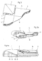
- FIGs. 2, 2a and 3, 3a are different views of a detail from a removable frame with connecting element according to the invention shown.
- the cover 2 In the fig. 2 and 2a, the cover 2 is in the closed position shown, whereas the cover 2 in Figs. 3 and 3a in the open Position is shown.
- the section shown in these figures from a Interchangeable frame is provided by frame strips 3, which over the base part 1 and cover 2 formed connecting element are interconnected, and a frame rear wall 18 fixed to the aforementioned elements educated.
- the cover 2 is shown in the closed position, and it can be seen that (shown in dashed lines) the cover strips 14 in this Position of the cover 2 extend partially below the latter.
- the cover strips 14 through Fold out from the frame level to open one in the frame remove the present object.
- the cover strips 14 are also in their open cover 2 Border areas free, so that they can move freely from the frame level can be folded down and thus the frame for inserting one Object can be opened.
- 3a in particular, that the cover 2 in the open position both to the side and upwards protrudes beyond the removable frame. This is done at an angle Frame level directed guidance of the cover 2 reached.
- FIGS. 4a and 4b In which a connecting element according to the invention with an attached thereto Frame bar 3 is shown in the closed or open position.
- a locking element in this drawing 23 which is part of the guide formed in the base part and a Latch 20 carries, can be recognized.
- the locking element 23 is on the base part 1 spring loaded.
- the locking lug 20 cooperates in the guide rail Cover 2 trained locking grooves 19a and 19b together by in this engages when the cover 2 is in the open or closed Position.
- the locking lug 20 engages in the locking groove 19a when the cover 2 is in the closed position and it engages in the Locking groove 19b when the cover 2 is in the open position.
- there is a projection on the guide rail of the cover 2 recognize which additionally limits the movement of the cover 2.
- the Projection 21 strikes in the closed position of the cover 2 formed on the base part 22 and thus prevents another Movement of the cover 2 in the closing direction. Forms in the open position the projection 21 on its surface adjacent to the locking groove 19b additional stop, which on the locking lug 20 of the locking element 23 in open position.
- the movement of the cover 2 is in Opening direction limited.
- the locking element 23 By applying a greater force, however the locking element 23 is pushed back due to its resilient mounting, so that the projection 21 slides over the latch 20 and thus the Cover 2 can be separated from the base part 1.
- a new cover 2 can be placed on one and the same base part.
- the user of the removable frame receives one additional creative freedom in the compilation of his used change frame.
- the projection 21 prevents posters, posters or the like Detach the cover 2 so that it cannot be lost.
- Figs. 5a and 5b is the base part of an inventive Connection element in perspective in a view from below or above shown.
- the top of this figure is Connecting web 4 as an alternative embodiment, an arranged thereon Teeth 4b shown.
- This can be used instead of the smooth outer surface of the Projections may be provided to improve the hold of the in the longitudinal groove Base bar introduced connecting web 4 to effect.
- Two guide rails 9 are laterally delimited, guide sections running essentially perpendicular to the frame plane guide grooves 26 arranged therein.
- the guide grooves 26 are in their Dimensions corresponding to the dimensions of the on the cover arranged guide rails 10 formed.
- the spring-loaded Detection element 23 is between the perpendicular to the The frame-level formed guide sections.
- This Locking element 23 is tongue-shaped and with one of its narrow edges connected to the base part.
- the resilient bearing is in this case by the Elasticity of the selected material of the base part 1 is generated.
- openings 24 and 25 can be seen through which to Attachment of a connecting element and thus an interchangeable frame, in which this connecting element is integrated on a wall or the like Screws, nails or similar fasteners can be performed.
- Figs. 6a and 6b are two views of the cap-like design Detect covers.
- 6a is the guide rail 10 in particular with the locking grooves 19a and 19b executed thereon and the projection 21 well to recognize. It can also be seen here how the guide rail 10 over a web 11 is connected to the cover.
- the web 11 runs here wedge-shaped, so that with respect to the frame plane an inclination of the Guide rail 10 is reached, the inclination of the guide grooves 26th corresponds.
- Fig. 6b can be seen that the cover 2 starting from Edge is formed with a rising curvature, which towards one over the Cover running diagonals falls off again.
- the side contour of the Cover corresponds to the outer contour of the cover strip on the Connecting element according to the invention adjacent frame bar, so that at closed cover 2 this lies against the cover strip.
- the shape of the cover can be different with a differently shaped cover strip his.
- the elements shown here are made in the illustrated embodiment Made of plastic.
- the base part and cover can be covered by Plastic injection molding are made.
Landscapes
- Mirrors, Picture Frames, Photograph Stands, And Related Fastening Devices (AREA)
Applications Claiming Priority (2)
| Application Number | Priority Date | Filing Date | Title |
|---|---|---|---|
| DE20007769U DE20007769U1 (de) | 2000-04-28 | 2000-04-28 | Verbindungselement zum Aufbau einer Eckverbindung zweier Rahmenleisten eines Wechselrahmens |
| DE20007769U | 2000-04-28 |
Publications (1)
| Publication Number | Publication Date |
|---|---|
| EP1149550A2 true EP1149550A2 (fr) | 2001-10-31 |
Family
ID=7940858
Family Applications (1)
| Application Number | Title | Priority Date | Filing Date |
|---|---|---|---|
| EP01106660A Withdrawn EP1149550A2 (fr) | 2000-04-28 | 2001-03-16 | Cornière pour assembler deux profilés d'un cadre pour image échangeable |
Country Status (3)
| Country | Link |
|---|---|
| US (1) | US20010034989A1 (fr) |
| EP (1) | EP1149550A2 (fr) |
| DE (1) | DE20007769U1 (fr) |
Cited By (6)
| Publication number | Priority date | Publication date | Assignee | Title |
|---|---|---|---|---|
| KR100975075B1 (ko) * | 2009-07-17 | 2010-08-11 | 주식회사 휴데코 | 고정부재 인비저블 타입 패널 프레임 구조 |
| US20190217658A1 (en) * | 2015-07-21 | 2019-07-18 | Tracer Imaging Llc | System for Mounting a Covering upon a Frame |
| US10813478B2 (en) | 2016-12-20 | 2020-10-27 | Tracer Imaging Llc | System for retaining an image within a frame |
| US11419436B2 (en) | 2019-06-19 | 2022-08-23 | Tracer Imaging Llc | Method for retaining a substrate within a frame |
| US11523693B2 (en) | 2020-07-31 | 2022-12-13 | Tracer Imaging Llc | Snap-fit framing system |
| US12329297B2 (en) | 2020-07-31 | 2025-06-17 | Tracer Imaging Llc | Framing system and wall pad therefor |
Families Citing this family (12)
| Publication number | Priority date | Publication date | Assignee | Title |
|---|---|---|---|---|
| DE10231094B4 (de) * | 2002-07-10 | 2004-07-29 | Axel Zacharias | Bilderrahmen |
| WO2007008935A2 (fr) * | 2005-07-11 | 2007-01-18 | Ready Solar, Inc. | Panneau et cadre solaire et procedes associes |
| US20070175123A1 (en) * | 2006-01-17 | 2007-08-02 | Richard Bernier | Trim system for doors and windows with corner block assembly |
| DE102008045510A1 (de) * | 2008-09-03 | 2010-03-04 | Sapa Gmbh | Solarmodulrahmen mit Wasserablauf |
| JP6045853B2 (ja) * | 2012-08-24 | 2016-12-14 | 駒村 武夫 | キャップ付きフレーム |
| US9631417B2 (en) * | 2012-12-21 | 2017-04-25 | Milgard Manufacturing Incorporated | Screen corner attachment |
| DE102015116299A1 (de) | 2015-09-25 | 2017-03-30 | Achim Hartlieb | Bilderrahmen mit Gelenkanordnung |
| EP3749145A4 (fr) * | 2018-02-06 | 2022-01-26 | MCS Industries, Inc. | Système de suspension et support associé |
| US10939775B2 (en) * | 2018-03-20 | 2021-03-09 | Budnick Converting, Inc. | Modular framing system |
| USD964844S1 (en) | 2019-01-30 | 2022-09-27 | Mcs Industries, Inc. | Hanging bracket |
| US11373557B2 (en) * | 2019-07-23 | 2022-06-28 | Budnick Converting, Inc. | Frame assembly for displaying a tensionable textile media |
| USD1030329S1 (en) | 2021-01-12 | 2024-06-11 | Mcs Industries, Inc. | Hanging bracket for a frame |
Citations (2)
| Publication number | Priority date | Publication date | Assignee | Title |
|---|---|---|---|---|
| DE8416300U1 (de) | 1984-09-06 | Marketing-Displays Produktionsgesellschaft für Werbe- und Verkaufsförderungssysteme mbH, 5000 Köln | Klemmrahmen | |
| DE8806432U1 (de) | 1988-05-17 | 1988-07-07 | marketing-displays Produktionsgesellschaft für Werbe- und Verkaufsförderungssysteme mbH, 50767 Köln | Klemmrahmen |
-
2000
- 2000-04-28 DE DE20007769U patent/DE20007769U1/de not_active Expired - Lifetime
-
2001
- 2001-03-15 US US09/810,758 patent/US20010034989A1/en not_active Abandoned
- 2001-03-16 EP EP01106660A patent/EP1149550A2/fr not_active Withdrawn
Patent Citations (2)
| Publication number | Priority date | Publication date | Assignee | Title |
|---|---|---|---|---|
| DE8416300U1 (de) | 1984-09-06 | Marketing-Displays Produktionsgesellschaft für Werbe- und Verkaufsförderungssysteme mbH, 5000 Köln | Klemmrahmen | |
| DE8806432U1 (de) | 1988-05-17 | 1988-07-07 | marketing-displays Produktionsgesellschaft für Werbe- und Verkaufsförderungssysteme mbH, 50767 Köln | Klemmrahmen |
Cited By (12)
| Publication number | Priority date | Publication date | Assignee | Title |
|---|---|---|---|---|
| KR100975075B1 (ko) * | 2009-07-17 | 2010-08-11 | 주식회사 휴데코 | 고정부재 인비저블 타입 패널 프레임 구조 |
| US20190217658A1 (en) * | 2015-07-21 | 2019-07-18 | Tracer Imaging Llc | System for Mounting a Covering upon a Frame |
| US10981415B2 (en) * | 2015-07-21 | 2021-04-20 | Tracer Imaging Llc | System for mounting a covering upon a frame |
| US11548315B2 (en) | 2015-07-21 | 2023-01-10 | Tracer Imaging Llc | System for mounting a covering upon a frame |
| US10813478B2 (en) | 2016-12-20 | 2020-10-27 | Tracer Imaging Llc | System for retaining an image within a frame |
| US11684185B2 (en) | 2016-12-20 | 2023-06-27 | Tracer Imaging Llc | System for retaining an image within a frame |
| US11419436B2 (en) | 2019-06-19 | 2022-08-23 | Tracer Imaging Llc | Method for retaining a substrate within a frame |
| US11553808B2 (en) | 2019-06-19 | 2023-01-17 | Tracer Imaging Llc | System for retaining a substrate within a frame |
| US12364348B2 (en) | 2019-06-19 | 2025-07-22 | Tracer Imaging Llc | System for retaining a substrate within a frame |
| US11523693B2 (en) | 2020-07-31 | 2022-12-13 | Tracer Imaging Llc | Snap-fit framing system |
| US11857091B2 (en) | 2020-07-31 | 2024-01-02 | Tracer Imaging Llc | Snap-fit framing system |
| US12329297B2 (en) | 2020-07-31 | 2025-06-17 | Tracer Imaging Llc | Framing system and wall pad therefor |
Also Published As
| Publication number | Publication date |
|---|---|
| US20010034989A1 (en) | 2001-11-01 |
| DE20007769U1 (de) | 2000-08-03 |
Similar Documents
| Publication | Publication Date | Title |
|---|---|---|
| EP1149550A2 (fr) | Cornière pour assembler deux profilés d'un cadre pour image échangeable | |
| DE2855121C2 (fr) | ||
| EP1614369B1 (fr) | Cadre de tiroir | |
| DE3502791A1 (de) | Werbetraeger an einkaufswagen, wahlweise in verbindung mit oder ohne korbschutzecken | |
| EP3098362A1 (fr) | Systeme de montage d'un cadre en treillis | |
| DE69507529T2 (de) | Handgriff, insbesondere Etikettenhalter, für Wände und Wand, insbesondere damit ausgerüstete Schubladenvorderwand | |
| EP1070826B1 (fr) | Caisson de volet roulant | |
| DE4409420A1 (de) | Betätigungsvorrichtung für Handhaben von Türen und Fenstern | |
| WO2004019304A2 (fr) | Systeme de presentation pour ecran | |
| DE20005194U1 (de) | Wechselrahmen sowie Funktionselemente zur Verwendung mit demselben | |
| DE2933838C2 (de) | Wechselrahmen für Bilder, Photos o.dgl. | |
| DE2732880C3 (de) | Bausatz zum Herstellen von horizontal und vertikal erweiterbaren Schildern für Türen und Orientierungstafeln | |
| EP0342662B1 (fr) | Dispositif pour assembler des éléments de grilles décoratives | |
| DE602005000077T2 (de) | Rolladen zum Schutz einer Öffnung, insbesondere eines Fensters, einer Tür oder dergleichen | |
| DE3909926C2 (fr) | ||
| DE29809261U1 (de) | Wechselrahmen | |
| DE19513151C1 (de) | Vitrine zur Zurschaustellung von Gegenständen | |
| DE202019104971U1 (de) | Schubkastenblende | |
| DE3833608C2 (fr) | ||
| DE20008856U1 (de) | Treibstangenbeschlag-System mit Hochkant-Treibstange und Verzahnungsverbindungseinheit | |
| EP1136020A1 (fr) | Cadre de changement | |
| DE2262521C3 (de) | Basiselement | |
| DE19604542A1 (de) | Vorrichtung zur Aufnahme von Bildern oder dergleichen | |
| DE202015006738U1 (de) | Verbindungssystem zur dreidimensionalen Anordnung von Wandelementen | |
| DE1922830C3 (de) | Hinweisschild, insbesondere Türschild |
Legal Events
| Date | Code | Title | Description |
|---|---|---|---|
| PUAI | Public reference made under article 153(3) epc to a published international application that has entered the european phase |
Free format text: ORIGINAL CODE: 0009012 |
|
| AK | Designated contracting states |
Kind code of ref document: A2 Designated state(s): AT BE CH CY DE DK ES FI FR GB GR IE IT LI LU MC NL PT SE TR |
|
| AX | Request for extension of the european patent |
Free format text: AL;LT;LV;MK;RO;SI |
|
| STAA | Information on the status of an ep patent application or granted ep patent |
Free format text: STATUS: THE APPLICATION HAS BEEN WITHDRAWN |
|
| 18W | Application withdrawn |
Withdrawal date: 20020322 |