EP1149689A2 - Procédé et dispositif pour la compression d'un matériau pulvérulent en un article homogène - Google Patents
Procédé et dispositif pour la compression d'un matériau pulvérulent en un article homogène Download PDFInfo
- Publication number
- EP1149689A2 EP1149689A2 EP01850072A EP01850072A EP1149689A2 EP 1149689 A2 EP1149689 A2 EP 1149689A2 EP 01850072 A EP01850072 A EP 01850072A EP 01850072 A EP01850072 A EP 01850072A EP 1149689 A2 EP1149689 A2 EP 1149689A2
- Authority
- EP
- European Patent Office
- Prior art keywords
- moulding cavity
- powder material
- gas
- punch
- compacting
- Prior art date
- Legal status (The legal status is an assumption and is not a legal conclusion. Google has not performed a legal analysis and makes no representation as to the accuracy of the status listed.)
- Withdrawn
Links
Images
Classifications
-
- B—PERFORMING OPERATIONS; TRANSPORTING
- B22—CASTING; POWDER METALLURGY
- B22F—WORKING METALLIC POWDER; MANUFACTURE OF ARTICLES FROM METALLIC POWDER; MAKING METALLIC POWDER; APPARATUS OR DEVICES SPECIALLY ADAPTED FOR METALLIC POWDER
- B22F3/00—Manufacture of workpieces or articles from metallic powder characterised by the manner of compacting or sintering; Apparatus specially adapted therefor ; Presses and furnaces
- B22F3/004—Filling molds with powder
-
- B—PERFORMING OPERATIONS; TRANSPORTING
- B22—CASTING; POWDER METALLURGY
- B22F—WORKING METALLIC POWDER; MANUFACTURE OF ARTICLES FROM METALLIC POWDER; MAKING METALLIC POWDER; APPARATUS OR DEVICES SPECIALLY ADAPTED FOR METALLIC POWDER
- B22F3/00—Manufacture of workpieces or articles from metallic powder characterised by the manner of compacting or sintering; Apparatus specially adapted therefor ; Presses and furnaces
- B22F3/02—Compacting only
- B22F3/03—Press-moulding apparatus therefor
-
- B—PERFORMING OPERATIONS; TRANSPORTING
- B30—PRESSES
- B30B—PRESSES IN GENERAL
- B30B11/00—Presses specially adapted for forming shaped articles from material in particulate or plastic state, e.g. briquetting presses, tabletting presses
- B30B11/02—Presses specially adapted for forming shaped articles from material in particulate or plastic state, e.g. briquetting presses, tabletting presses using a ram exerting pressure on the material in a moulding space
- B30B11/027—Particular press methods or systems
-
- B—PERFORMING OPERATIONS; TRANSPORTING
- B30—PRESSES
- B30B—PRESSES IN GENERAL
- B30B15/00—Details of, or accessories for, presses; Auxiliary measures in connection with pressing
- B30B15/0005—Details of, or accessories for, presses; Auxiliary measures in connection with pressing for briquetting presses
- B30B15/0017—Deairing means
-
- B—PERFORMING OPERATIONS; TRANSPORTING
- B30—PRESSES
- B30B—PRESSES IN GENERAL
- B30B15/00—Details of, or accessories for, presses; Auxiliary measures in connection with pressing
- B30B15/30—Feeding material to presses
- B30B15/302—Feeding material in particulate or plastic state to moulding presses
-
- B—PERFORMING OPERATIONS; TRANSPORTING
- B22—CASTING; POWDER METALLURGY
- B22F—WORKING METALLIC POWDER; MANUFACTURE OF ARTICLES FROM METALLIC POWDER; MAKING METALLIC POWDER; APPARATUS OR DEVICES SPECIALLY ADAPTED FOR METALLIC POWDER
- B22F2999/00—Aspects linked to processes or compositions used in powder metallurgy
Definitions
- the present invention relates to a method and an apparatus for compacting a powder material into a homogenous article.
- the object of the present invention is to solve these problems by providing a method and an apparatus for compacting a powder material into a homogenous article in which the particles in the powder are evenly distributed within the moulding cavity and the upper surface of the powder in the moulding cavity is horizontal before the start of the pressing step.
- This object is accomplished by a method for compacting a powder material into a homogenous article, characterised by the steps of; placing the powder material in a moulding cavity connected to a gas source, blowing gas into the lower end of the moulding cavity so that the particles in the powder material are suspended in a gas stream, sealing the upper end of the moulding cavity by an upper pressing punch, connecting the lower end of the moulding cavity to a vacuum source, sealing the connection to the vacuum source by moving a lower punch relative to the lower end portion of the moulding cavity, and thereafter compacting the powder material with the help of the pressing punch.
- the vacuum source creates a sub-pressure in the moulding cavity of at least half the atmospheric pressure.
- the invention relates also to an apparatus for compacting a powder material into a homogenous article
- a moulding cavity having vertical side walls and open ends, and an upper and a lower punch having the same cross-sectional area as the moulding cavity and being movable into and out of the moulding cavity, characterised in that an opening is arranged in the side wall of the moulding cavity in the lower end part thereof, said opening being connected to a device for blowing gas into and a device for sucking gas out of the moulding cavity, and that the lower punch is movable relative to the moulding cavity from a first position in which the upper end surface of the punch is located below the opening and a second position in which the opening is covered by the side wall of the lower punch.
- a gas-pervious membrane covers the opening, said membrane being impervious for the smallest of the particles in the powder material to be placed in the moulding cavity.
- the vertical walls of the moulding cavity consist of the inner wall of a matrix having the form of a hollow cylinder and the side wall of a cylindrical core pin concentrically located in the inner space defined by the hollow matrix, and the upper and lower punch has a lower respectively an upper end surface comprising an annular flange fitting into the annular moulding cavity, the opening connected to a device for blowing gas into and a device for sucking gas out of the moulding cavity comprising an annular groove in the lower end portion of the inner wall of the matrix and/or the side wall of the core pin.
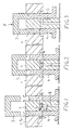
- FIG. 1-3 An apparatus for compacting powder into solid annular articles, such as bearing rings, is shown in Figures 1-3.
- the apparatus comprises a hollow cylindrical matrix 1, a core pin 2, an upper pressing punch 3 and a lower punch 4.
- the core pin 2 is cylindrical and concentrically disposed in relation to the matrix 1 so that the side walls of a moulding cavity 5 is defined by the inner wall of the matrix and the side wall of the core pin.
- the bottom wall of the moulding cavity 5 is defined by the upper end surface of the lower punch 4 having the form of a hollow cylinder fitting into the annular space between the inner side wall of the matrix and the side wall of the core pin.
- the upper punch 3 has the form of a hollow cylinder with a closed upper end.
- the matrix 1 has an annular groove 6 in the lower end portion thereof.
- the groove 6 is by suitable conduits in communication with a gas source (not shown in the Figures).
- a similar annular groove 7 is made in the core pin 2.
- This groove 7 is also in communication with the gas source by suitable conduits.
- the groove 7 is connected to a central bore 8 by at least two radial bores.
- the central bore 8 is by a suitable conduit connected to the same gas source as the groove 6.
- the side of the respective groove 6,7 that is turned against the moulding cavity 5 is closed by a gas-permeable membrane 9 and 10, respectively.
- Figure 1 the apparatus is shown in the beginning of the compacting process immediately after powder material has been introduced into the moulding cavity 5.
- gas is blown into the moulding cavity by the gas source, as is indicated by arrows in Figure 1.
- the flow rate of the gas is such that a fluidised bed is accomplished, i.e. the particles in the powder material are suspended by the gas flow. Thereby an even distribution of the particles in the powder material and a horizontal upper particle surface will be established.
- the flow rate for creating a fluidised bed is dependent of the density, size and form of the particles in the powder material.
- the gas flow is created after the filling of the moulding cavity with powder material.
- the gas flow first reaches the bottom of the moulding cavity, it has a stirring effect on the powder material in the moulding cavity that ensures an even distribution of the particles in the powder material when a flow rate sufficient for suspending the particles of the powder material is reached. It is pointed out that the flow rate should be successively increased in order to avoid a sudden increase of pressure in the moulding cavity, which might result in that some of the particles in the moulding cavity will be thrown out from the moulding cavity.
- the gas flow in the moulding cavity is created immediately before the moulding cavity is filled with powder material.
- the pressure drop over the moulding cavity will successively increase during the filling of the moulding cavity so there will be no risk of a sudden pressure increase therein.
- the lower punch 4 is preferably moved upwards from the position shown in Figure 1 so that the upper surface of the powder material filled into the moulding cavity will lie flush with the upper surfaces of the core pin and the matrix. Superfluous powder material filled into the moulding cavity can then be scraped of. Thereafter, the lower punch is moved downwards to the position shown in Figure 1 and the gas flow is created.
- the gas used can be air or an inert gas.
- sealing elements (not shown in the figures) between the matrix and the upper and lower punch, respectively.
- the sealing element for the lower punch is preferably fixed to the matrix whereas the sealing element for the upper punch is slidably attached to the upper punch and pretensioned to a position in which the sealing element lies flush with the lower surface of the upper punch.
- the lower punch 4 is moved upwards such a distance that the grooves 6,7 are covered by the outer side wall thereof and the grooves 6,7 are disconnected from the vacuum source.
- the powder material in the moulding cavity will move upwards together with the lower punch 4 and in the end position of the lower punch, which is shown in Figure 3, the upper surface of the powder material is in abutment with the lower end surface of the upper punch 3.
- the apparatus is now ready for the compacting of the powder material in the moulding cavity and a the pressing punch 3 is driven downwards with a force P, as indicated by an arrow in Figure 3.
- the pressing punch is driven with a very high pressing rate, the pressing operation will only take a few milliseconds.
- the lower punch 4 is advantageously arranged to eject the compacted article out of the moulding cavity 5 after the pressing step has been performed.
- openings 9,10 are present in both the matrix and the core pin.
- the openings are only provided in the matrix. In such a case it is possible to make the matrix movable in relation to the lower punch in order to open and close this opening. Such an alternative would facilitate the support of the lower punch during the pressing operation.
- the invention can also be performed for compacting articles into solid bodies, such as a cylinder.
- the apparatus does not include a core pin so that openings would only be present in the matrix, which then preferably is movable in relation to the lower punch in order to close and open the openings to the moulding cavity.
- the embodiment described can be modified in several ways within the scope of the invention.
- the grooves 6,7 can for example be connected to different gas and vacuum sources, but preferably they are connected to the same gas and vacuum source.
- the respective gas and vacuum source can for example be the outlet and the inlet, respectively of a blower but it is also possible to use separate sources for creating the flow of gas and the vacuum.
- the moulding cavity can have another form so that articles with other shapes than rings can be made, for example tubes with a rectangular or U-shaped section. The invention should therefore only be restricted by the wording of the enclosed patent claims.
Landscapes
- Engineering & Computer Science (AREA)
- Mechanical Engineering (AREA)
- Manufacturing & Machinery (AREA)
- Powder Metallurgy (AREA)
- Processing And Handling Of Plastics And Other Materials For Molding In General (AREA)
- Casting Or Compression Moulding Of Plastics Or The Like (AREA)
Applications Claiming Priority (2)
| Application Number | Priority Date | Filing Date | Title |
|---|---|---|---|
| SE0001522A SE0001522L (sv) | 2000-04-27 | 2000-04-27 | Förfarande och anordning för att kompaktera ett pulvermaterial till en homogen artikel |
| SE0001522 | 2000-04-27 |
Publications (2)
| Publication Number | Publication Date |
|---|---|
| EP1149689A2 true EP1149689A2 (fr) | 2001-10-31 |
| EP1149689A3 EP1149689A3 (fr) | 2003-02-12 |
Family
ID=20279433
Family Applications (1)
| Application Number | Title | Priority Date | Filing Date |
|---|---|---|---|
| EP01850072A Withdrawn EP1149689A3 (fr) | 2000-04-27 | 2001-04-20 | Procédé et dispositif pour la compression d'un matériau pulvérulent en un article homogène |
Country Status (8)
| Country | Link |
|---|---|
| US (1) | US6406663B1 (fr) |
| EP (1) | EP1149689A3 (fr) |
| JP (1) | JP2001300789A (fr) |
| KR (1) | KR20010098848A (fr) |
| CN (1) | CN1320520A (fr) |
| BR (1) | BR0101599A (fr) |
| CA (1) | CA2344006A1 (fr) |
| SE (1) | SE0001522L (fr) |
Cited By (2)
| Publication number | Priority date | Publication date | Assignee | Title |
|---|---|---|---|---|
| WO2005030116A1 (fr) * | 2003-09-24 | 2005-04-07 | Bioprogress Technology Limited | Perfectionnements relatifs au compactage et a l'enrobage d'une poudre |
| EP3342586A4 (fr) * | 2015-08-25 | 2018-09-26 | Sumitomo Electric Industries, Ltd. | Moule métallique de moulage à partir de poudres et procédé de fabrication de moulage compacté à partir de poudre |
Families Citing this family (18)
| Publication number | Priority date | Publication date | Assignee | Title |
|---|---|---|---|---|
| US7237730B2 (en) * | 2005-03-17 | 2007-07-03 | Pratt & Whitney Canada Corp. | Modular fuel nozzle and method of making |
| JP4561644B2 (ja) * | 2006-01-30 | 2010-10-13 | Tdk株式会社 | 粉末成形方法及び粉末成形装置 |
| US8316541B2 (en) * | 2007-06-29 | 2012-11-27 | Pratt & Whitney Canada Corp. | Combustor heat shield with integrated louver and method of manufacturing the same |
| US7543383B2 (en) | 2007-07-24 | 2009-06-09 | Pratt & Whitney Canada Corp. | Method for manufacturing of fuel nozzle floating collar |
| US8328966B1 (en) * | 2008-09-11 | 2012-12-11 | The United States Of America As Represented By The Secretary Of The Navy | Method for making miniature explosive powder charges |
| US8382921B1 (en) * | 2008-09-11 | 2013-02-26 | The United States Of America As Represented By The Secretary Of The Navy | Apparatus for making miniature explosive powder charges |
| CN101961786A (zh) * | 2010-09-21 | 2011-02-02 | 重庆文理学院 | 一种圆形样高温真空保护气氛烧结模具及工艺 |
| CN102689450B (zh) * | 2012-05-31 | 2014-10-22 | 清华大学 | 准等静压真空液压机 |
| JP5821111B1 (ja) * | 2015-01-16 | 2015-11-24 | 小林工業株式会社 | 金型装置 |
| CN105922620B (zh) * | 2016-05-17 | 2017-09-22 | 鹤山联塑实业发展有限公司 | 一种阻火圈芯材的制造加工方法 |
| KR102328258B1 (ko) | 2017-10-17 | 2021-11-18 | 주식회사 엘지에너지솔루션 | 리튬 금속 전지용 전해질 및 이를 포함하는 리튬 금속 전지 |
| CN109968727B (zh) * | 2019-03-16 | 2019-12-24 | 梁仓平 | 利用秸秆制取生物质能源的冲压成型机 |
| CN111136263B (zh) * | 2020-02-14 | 2024-11-26 | 博罗县何氏模具制造有限公司 | 一种粉末成型机的吹料回收装置 |
| IT202100002525A1 (it) * | 2021-02-04 | 2022-08-04 | Sacmi | Apparato e metodo per riempire uno stampo. |
| CN113333745A (zh) * | 2021-05-18 | 2021-09-03 | 中国工程物理研究院材料研究所 | 一种具有气氛保护功能的粉末压制模具及方法 |
| CN113715396A (zh) * | 2021-08-20 | 2021-11-30 | 山西江淮重工有限责任公司 | 粉末状材料单向压制成型的装置及压制成型的方法 |
| CN115781874B (zh) * | 2022-11-02 | 2025-05-13 | 深圳市嘉杰诚文化传媒有限公司 | 一种双管实验压实功能陶瓷粉末设备 |
| CN116944497B (zh) * | 2023-09-18 | 2023-12-08 | 泰州市华诚钨钼制品有限公司 | 一种钨钼合金件成型压制设备 |
Family Cites Families (11)
| Publication number | Priority date | Publication date | Assignee | Title |
|---|---|---|---|---|
| DE707612C (de) * | 1939-09-27 | 1941-06-27 | Hans Blache | Verfahren zum Herstellen hohlfoermiger Presslinge auf einer Tablettenpresse |
| GB1304162A (fr) | 1968-12-30 | 1973-01-24 | ||
| CH514415A (de) * | 1969-08-15 | 1971-10-31 | Polygest Ag | Verfahren zur homogenen Verteilung eines Pulvers und nachfolgender Verformung sowie Vorrichtung zur Ausführung des Verfahrens |
| BE754830A (fr) * | 1969-11-10 | 1971-01-18 | Wolverine Pentronix | Appareil pour injecter un fluide dans des matieres reduites en poudre en cours de tassement |
| DE3128347A1 (de) | 1981-07-17 | 1983-02-03 | Eugen Dipl.-Ing. 8871 Burtenbach Bühler | Verfahren und einrichtung zur herstellung von formlingen aus rieselfaehiger masse stichwort: "beibehaltung des fuellvakuums beim isostatischen pressen" |
| DE3144678A1 (de) * | 1981-11-10 | 1983-05-19 | Eugen Dipl.-Ing. 8871 Burtenbach Bühler | Verfahren und einrichtung zur herstellung von formlingen aus einer rieselfaehigen masse |
| US4518335A (en) | 1984-03-14 | 1985-05-21 | Allied Corporation | Dilatant mold and dilatant molding apparatus |
| EP0446665A1 (fr) | 1990-03-14 | 1991-09-18 | Asea Brown Boveri Ag | Procédé de préparation d'une ébauche à partir d'une poudre métallique ou céramique |
| IT1259950B (it) * | 1992-04-29 | 1996-03-28 | Int Stampi Srl | Stampo, in particolare, per la formatura di prodotti ceramici "crudi" |
| US5897826A (en) * | 1996-06-14 | 1999-04-27 | Materials Innovation, Inc. | Pulsed pressurized powder feed system and method for uniform particulate material delivery |
| JP3518969B2 (ja) * | 1996-10-24 | 2004-04-12 | 株式会社小松製作所 | 鋳型中子の造型方法および造型装置 |
-
2000
- 2000-04-27 SE SE0001522A patent/SE0001522L/xx not_active Application Discontinuation
-
2001
- 2001-04-17 CA CA002344006A patent/CA2344006A1/fr not_active Abandoned
- 2001-04-20 EP EP01850072A patent/EP1149689A3/fr not_active Withdrawn
- 2001-04-23 US US09/839,150 patent/US6406663B1/en not_active Expired - Fee Related
- 2001-04-24 JP JP2001125197A patent/JP2001300789A/ja active Pending
- 2001-04-25 KR KR1020010022202A patent/KR20010098848A/ko not_active Ceased
- 2001-04-25 BR BR0101599-0A patent/BR0101599A/pt not_active Application Discontinuation
- 2001-04-27 CN CN01117178A patent/CN1320520A/zh active Pending
Cited By (10)
| Publication number | Priority date | Publication date | Assignee | Title |
|---|---|---|---|---|
| WO2005030116A1 (fr) * | 2003-09-24 | 2005-04-07 | Bioprogress Technology Limited | Perfectionnements relatifs au compactage et a l'enrobage d'une poudre |
| EP1908444A1 (fr) * | 2003-09-24 | 2008-04-09 | BioProgress Technology Limited | Perfectionnements relatifs au compactage et a l'enrobage d'une poudre |
| EP1908448A1 (fr) * | 2003-09-24 | 2008-04-09 | BioProgress Technology Limited | Perfectionnements relatifs au compactage et a l'enrobage d'une poudre |
| EP1908446A1 (fr) * | 2003-09-24 | 2008-04-09 | BioProgress Technology Limited | Perfectionnements relatifs au compactage et a l'enrobage d'une poudre |
| EP1908445A1 (fr) * | 2003-09-24 | 2008-04-09 | BioProgress Technology Limited | Perfectionnements relatifs au compactage et a l'enrobage d'une poudre |
| EP1908447A3 (fr) * | 2003-09-24 | 2008-04-16 | BioProgress Technology Limited | Perfectionnements relatifs au compactage et à l'enrobage d'une poudre |
| US7625622B2 (en) | 2003-09-24 | 2009-12-01 | Bioprogress Technology Limited | Powder compaction and enrobing |
| US7785089B2 (en) | 2003-09-24 | 2010-08-31 | Bioprogress Technology Limited | Additional improvements in powder compaction and enrobing |
| EP3342586A4 (fr) * | 2015-08-25 | 2018-09-26 | Sumitomo Electric Industries, Ltd. | Moule métallique de moulage à partir de poudres et procédé de fabrication de moulage compacté à partir de poudre |
| US11167517B2 (en) | 2015-08-25 | 2021-11-09 | Sumitomo Electric Industries, Ltd. | Powder compaction mold and method for manufacturing powder compact |
Also Published As
| Publication number | Publication date |
|---|---|
| CN1320520A (zh) | 2001-11-07 |
| CA2344006A1 (fr) | 2001-10-27 |
| BR0101599A (pt) | 2001-12-04 |
| KR20010098848A (ko) | 2001-11-08 |
| US20020025271A1 (en) | 2002-02-28 |
| EP1149689A3 (fr) | 2003-02-12 |
| US6406663B1 (en) | 2002-06-18 |
| SE0001522D0 (sv) | 2000-04-27 |
| SE0001522L (sv) | 2001-10-28 |
| JP2001300789A (ja) | 2001-10-30 |
Similar Documents
| Publication | Publication Date | Title |
|---|---|---|
| US6406663B1 (en) | Method and apparatus for compacting a powder material into a homogenous article | |
| US6241935B1 (en) | Pulsed pressurized powder feed system and method for uniform particulate material delivery | |
| US4518335A (en) | Dilatant mold and dilatant molding apparatus | |
| JPH0136404B2 (fr) | ||
| US5937263A (en) | Cup-shaped porous metal ultra-high efficiency filter and method of making same | |
| KR20010092775A (ko) | 사형의 조형 장치 및 그 방법 | |
| US6155028A (en) | Method and apparatus for packing material | |
| US5039296A (en) | Apparatus for producing pressings provided with channels from powdery moulding compound, especially ceramic molding compound(short title: honeycomb) | |
| CN100522543C (zh) | 用于通过压塑法成形塑料物品的方法及设备 | |
| US6733260B2 (en) | Powder filling method and arrangement therefor | |
| JP3164271B2 (ja) | 鋳型造型装置 | |
| US4069858A (en) | Manufacture of foundry moulds and cores | |
| JP2938946B2 (ja) | 粉状物充填真空室を使用する反重力式注型方法 | |
| US3144683A (en) | Material compacting and mold charging apparatus | |
| EP0490701B1 (fr) | Machine de compactage à air comprimé, pour la fabrication de moules en sable de fonderie | |
| JP2008509015A (ja) | 合成樹脂容器用の予備成形物の圧縮成形方法及び装置 | |
| JPH08257798A (ja) | 粉体加圧充填装置および方法 | |
| JPS5855149A (ja) | ガス硬化式主型造型装置 | |
| JPH1177242A (ja) | 鋳型造型装置 | |
| US4009747A (en) | Method of and device for forming vacuum sealed molds | |
| JP3197472B2 (ja) | 乾式静水圧加圧成形装置及び乾式静水圧加圧成形方法 | |
| CN111148620B (zh) | 用于3d打印系统的构建材料料斗 | |
| MXPA05011492A (es) | Aparato formador de moldes de arena. | |
| US20100043916A1 (en) | Filling shoe and method for powder filling and compaction | |
| JPS59197503A (ja) | 横方向に貫通孔を有する圧粉成形体の成形方法 |
Legal Events
| Date | Code | Title | Description |
|---|---|---|---|
| PUAI | Public reference made under article 153(3) epc to a published international application that has entered the european phase |
Free format text: ORIGINAL CODE: 0009012 |
|
| AK | Designated contracting states |
Kind code of ref document: A2 Designated state(s): AT BE CH CY DE DK ES FI FR GB GR IE IT LI LU MC NL PT SE TR |
|
| AX | Request for extension of the european patent |
Free format text: AL;LT;LV;MK;RO;SI |
|
| PUAL | Search report despatched |
Free format text: ORIGINAL CODE: 0009013 |
|
| AK | Designated contracting states |
Designated state(s): AT BE CH CY DE DK ES FI FR GB GR IE IT LI LU MC NL PT SE TR |
|
| AX | Request for extension of the european patent |
Extension state: AL LT LV MK RO SI |
|
| RIC1 | Information provided on ipc code assigned before grant |
Ipc: 7B 30B 15/00 B Ipc: 7B 30B 15/30 B Ipc: 7B 30B 11/02 A |
|
| 17P | Request for examination filed |
Effective date: 20030812 |
|
| AKX | Designation fees paid |
Designated state(s): AT BE CH CY DE DK ES FI FR GB GR IE IT LI LU MC NL PT SE TR |
|
| STAA | Information on the status of an ep patent application or granted ep patent |
Free format text: STATUS: THE APPLICATION HAS BEEN WITHDRAWN |
|
| 18W | Application withdrawn |
Effective date: 20050826 |