EP1149696A2 - Offsetdruckwerk für eine Druckmaschine - Google Patents
Offsetdruckwerk für eine Druckmaschine Download PDFInfo
- Publication number
- EP1149696A2 EP1149696A2 EP01108985A EP01108985A EP1149696A2 EP 1149696 A2 EP1149696 A2 EP 1149696A2 EP 01108985 A EP01108985 A EP 01108985A EP 01108985 A EP01108985 A EP 01108985A EP 1149696 A2 EP1149696 A2 EP 1149696A2
- Authority
- EP
- European Patent Office
- Prior art keywords
- application roller
- plate cylinder
- roller
- offset printing
- contact zone
- Prior art date
- Legal status (The legal status is an assumption and is not a legal conclusion. Google has not performed a legal analysis and makes no representation as to the accuracy of the status listed.)
- Granted
Links
- 238000007645 offset printing Methods 0.000 title claims abstract description 33
- 238000007639 printing Methods 0.000 title claims description 26
- 238000007747 plating Methods 0.000 claims description 52
- 238000011144 upstream manufacturing Methods 0.000 claims description 3
- 230000002146 bilateral effect Effects 0.000 claims description 2
- XLYOFNOQVPJJNP-UHFFFAOYSA-N water Substances O XLYOFNOQVPJJNP-UHFFFAOYSA-N 0.000 abstract 3
- 238000012876 topography Methods 0.000 description 19
- 230000002093 peripheral effect Effects 0.000 description 18
- 238000011161 development Methods 0.000 description 7
- 230000018109 developmental process Effects 0.000 description 7
- 238000005253 cladding Methods 0.000 description 5
- 239000003973 paint Substances 0.000 description 4
- 238000000926 separation method Methods 0.000 description 4
- 230000006735 deficit Effects 0.000 description 2
- 230000001419 dependent effect Effects 0.000 description 2
- 238000000034 method Methods 0.000 description 2
- 238000010008 shearing Methods 0.000 description 2
- 238000012549 training Methods 0.000 description 2
- LFQSCWFLJHTTHZ-UHFFFAOYSA-N Ethanol Chemical compound CCO LFQSCWFLJHTTHZ-UHFFFAOYSA-N 0.000 description 1
- 241000237858 Gastropoda Species 0.000 description 1
- 230000005540 biological transmission Effects 0.000 description 1
- 230000015556 catabolic process Effects 0.000 description 1
- 230000006835 compression Effects 0.000 description 1
- 238000007906 compression Methods 0.000 description 1
- 230000000694 effects Effects 0.000 description 1
- 230000001804 emulsifying effect Effects 0.000 description 1
- 238000005516 engineering process Methods 0.000 description 1
- 230000001771 impaired effect Effects 0.000 description 1
- 239000012535 impurity Substances 0.000 description 1
- 239000002245 particle Substances 0.000 description 1
- 238000007493 shaping process Methods 0.000 description 1
- 239000000758 substrate Substances 0.000 description 1
- 238000009736 wetting Methods 0.000 description 1
Images


Classifications
-
- B—PERFORMING OPERATIONS; TRANSPORTING
- B41—PRINTING; LINING MACHINES; TYPEWRITERS; STAMPS
- B41F—PRINTING MACHINES OR PRESSES
- B41F7/00—Rotary lithographic machines
- B41F7/20—Details
- B41F7/24—Damping devices
- B41F7/26—Damping devices using transfer rollers
Definitions
- the invention relates to an offset printing unit for a printing press, the one a printing form-bearing plate cylinder, which at least with on and adjustable inking rollers of an inking unit are functionally connected, has, according to the preamble of the independent claims.
- An offset printing unit of this type is from DE 34 16 845 A1 with an inking unit and a dampening system. Then the dampening system is in the Essentially from a supply device for the dampening solution with a Device for dosing the dampening solution film and an applicator roller transfers the dampening solution film to a plate cylinder and with the adjacent inking unit can be coupled or operated separately.
- the dampening roller can be different from the plate cylinder Have peripheral speed, so that for example foreign particles eliminating wiping effect.
- an offset printing unit which is universal in Offset printing is operable.
- the offset printing unit is of the operating mode Wet offset can be changed to dry offset mode by using the ink-carrying plate cylinder in contact with a dampening roller Separation point decoupled from a dampening solution supply and with a Differential speed to the peripheral speed of the plate cylinder is drivable.
- the disadvantage here is that in the contact zone with the Plate cylinder a breakdown of color or a color split occurs and that thereby an uneven color and an impairment of Print quality occurs.
- DE 4423286 A1 is a printing unit for a rotary offset printing press with a plate cylinder, which one for the dampening agent-free offset printing suitable pressure plate carries, known.
- the inking unit is to be eliminated an additional roller assigned to impurities, which in a first Operating position can be set independently of the inking rollers on the printing plate is and against the direction of rotation of the plate cylinder with a Circumferential speed of the plate cylinder deviates Peripheral speed is drivable.
- a second operating position Additional roller - starting from the first operating position - into the inking unit integrated.
- the invention is based on the object of an offset printing unit at the outset to create described type that avoids the disadvantages mentioned, the in particular, process-stable color guidance on a plate cylinder supports and noticeably improves the print quality.
- a first advantage of the invention is that in the direction of rotation of the Plate cylinder in front of an inking unit arranged in the Wet offset operation with a dampening solution supply or in dry offset operation with a dampening solution-free offset printing with interrupted or switched off or can be used without a dampening solution supply and in all operating modes the print quality is noticeably improved. It was found that on the outer surface of such an application roller in Direction of rotation after tearing off paint or splitting color, especially when tearing off in a contact zone of Applicator roller and ink-guiding plate cylinder, no uniform Color distribution - viewed across the roller width - is present.
- the application roller is uneven in the direction of rotation Surface topography after such a contact zone at least before a renewed demolition of color or a color split in another Contact zone can be switched on and preferably switched off by means of at least one in parallel arranged plating device is leveled.
- Another advantage is that in addition to the on the outer surface of the Application roller leveled surface topography by means of at least one Plating device the subject-related color structure on the applicator roller is equalizable.
- the leveling of the color structure and the leveled Surface topography stabilize the in wet offset operation Dampening solution feed to the application roller and from the application roller to the Plate cylinder, reducing the risk of emulsifying in the inking unit, thereby the process-stable ink flow on the plate cylinder or in the inking unit is supported, and noticeably improve the print quality on the substrate.
- the arrangement of at least one plating device on the lateral surface of the applicator roller reduces the tendency to stenciling (shadow-like markings) during printing and the cord strips causing an uneven printing. It has been found that in wet offset printing with the application roller and at least one associated plating device, the dampening solution supply from the dampening roller to the application roller can be reduced and the use of alcohol can also be reduced. It is furthermore advantageous that the applicator roller can be driven to the plate cylinder with either the same or different circumferential speed and that the plating device causes a change in shape of the ink tips, ink domes and ink troughs after tearing or ink splitting towards a flat surface topography.
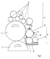
- a plate cylinder 1 carries a printing form and is shown in FIG. 1 with a Blanket cylinder 2, a dampening unit 3 and a downstream inking unit 4 in functional connection.
- the inking unit 4 consists of several on and color rollers 5, which are arranged so as to be adjustable, with rollers to be supplied with ink (not designated further) are connected.
- the dampening unit 3 is - in the direction of rotation of the plate cylinder 1 considered - upstream of the inking unit 4 and consists in present example from a dampening solution container 9, a dampening duct 7, a metering roller 8 and an applicator roller 6.
- the applicator roller 6 is in one first contact zone 12 with the inkable via the inking unit 4 Plate cylinder 1 can be switched on and off in a functional connection. At least that The dampening solution container 9 and the dampening duct 7 form the Fountain solution supply device, which in a second contact zone 16 with the Application roller 6 is in functional connection.
- At least one plating device 11 can be placed on the lateral surface of the applicator roller 6 in parallel, and preferably placed on it.
- the application roller 6 can be driven optionally with a peripheral speed that is the same as or different from the peripheral speed of the plate cylinder 1.
- at least one plating device 11 is preferably arranged in the direction of rotation of the application roller 6 in front of the dampening solution supply 7-9 which is functionally connected to the application roller 6 in the second contact zone 16.
- a further (structurally identical) plating device 11 is arranged on and off the outer surface of the application roller 6.
- the application roller 6 is in the direction of rotation after the first Contact zone 12 with the plate cylinder 1 at least one plating device 11 arranged on and off on the lateral surface of the applicator roller 6 and the Applicator roller 6 is optionally with a to the peripheral speed of Plate cylinder 1 same or different peripheral speed drivable and with the dampening solution supply switched off 7- 9 in the first Contact zone 12 placed on the plate cylinder 1.
- the offset printing unit no dampening.
- the application roller 6 in the direction of rotation of the plate cylinder 1 is arranged upstream of the inking rollers 5 of the inking unit 4.
- the plate cylinder 1 carries one for printing form suitable for dampening agent-free offset printing.
- the plate cylinder 1 the inking rollers 5 of the inking unit 4 are in turn assigned Color the printing form with a printing ink suitable for dry offset.
- the applicator roller 6 is independent of the inking rollers 5 ink-carrying printing form or the plate cylinder 1 in the first contact zone 12 arranged on and off.
- the application roller 6 is in the direction of rotation after the first contact zone 12, in which a tearing off of paint or a color splitting takes place, at least one plating device 11 can be switched on and preferably switched off
- the outer surface of the applicator roller 6 is arranged.
- the application roller 6 is there optionally with the same or different circumferential speed - based on the peripheral speed of the plate cylinder 1 - can be driven in rotation, for example via a switchable positive drive.
- At least one plating device 11 is coupled to an axially acting traversing drive.
- all plating devices 11 are coupled to such a traversing drive.
- the traversing drive is preferably functionally connected to the drivable plate cylinder 1 in terms of transmission technology.
- the plating device 11 arranged in front of the contact zone 16 can be driven to be changeable.
- the applicator roller 6 is optionally available with a The peripheral speed of the plate cylinder 1 is the same or different Peripheral speed drivable.
- the applicator roller 6 is on the drive side preferably geared technically with the drivable plate cylinder 1 in Functional connection.
- the plating devices 11 are preferably in their direction of rotation of the application roller 6 Arranged tangentially or secant-shaped on the lateral surface of the applicator roller 6 and arranged. Each plating device 11 can preferably be set against the outer surface of the application roller 6 by means of a force F, for example applied by a compression spring. A plating device 11 can preferably also be used to apply a uniform surface pressure over the width of the application roller 6 or the uneven surface topography of the ink.
- the plating device 11 is in its Inclination angle to the outer surface of the application roller 6 adjustable.
- At least one plating device 11 consists of a plating element 13, which extends over the width of the application roller 6 and is detachably arranged in a holder 14.
- the holder 14 is preferably arranged on the frame side in a bilateral bearing 15.
- At least one plating device 11 is preferably arranged in a bearing 15 on both sides in the direction of rotation of the applicator roller 6, for example in one swivel joint each.
- the bearing 15 is movable in such a way that the cladding element 11 is arranged so as to be adjustable in its angle of inclination (FIG. 6.7 double arrow) relative to the application roller 6.
- the free end of the cladding element 13 is arranged tangentially or secantly on the lateral surface of the application roller 6, preferably ending in a tangent or secant point.
- the free end of the preferably adjustable plating element 13 ends at a slight distance from the outer surface of the application roller 6. The distance is such that a leveling of an uneven surface topography 19 can be achieved.
- the plate cylinder 1 In an operating mode for dry offset, the plate cylinder 1 carries one for the Suitable printing form for dampening agent-free offset printing.
- the plate cylinder 1 are in turn assigned the inking rollers 5 of the inking unit 4, which the Color the printing form with a printing ink suitable for dry offset.
- the Applicator roller 6 is in the direction of rotation of the plate cylinder 1 before Ink application rollers 5 arranged. Furthermore, the applicator roller 6 is independent from the inking rollers 5 to the ink-guiding printing form or the Plate cylinder 1 arranged in the first contact zone 12 on and off.
- the application roller 6 is in the direction of rotation after the first contact zone 12 in the tearing off or splitting of color takes place, at least one Plating device 11 can be switched on and preferably switched off to the lateral surface of the Application roller 6 arranged.
- the application roller 6 is optionally the same or uneven peripheral speed - based on the Peripheral speed of the plate cylinder 1 - can be driven in rotation, for example via a switchable positive drive.
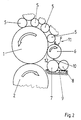
- the applicator roller 6 is for the dry offset mode at least one plating device 11 to the inking rollers 5 of the Inking unit 4 separately, in the direction of rotation of the plate cylinder 1, in front of the inking unit 4 arranged and forms with the plate cylinder 1, the first contact zone 12.
- FIG. 4 shows a further development, such that the application roller 6 with at least one plating device 11, in the direction of rotation of the plate cylinder 1, is arranged in front of the inking unit 4 and with the plate cylinder 1 Contact zone 12 forms.
- the applicator roller 6 is a bridge roller 17 in Contact associated with that in the direction of rotation of the plate cylinder 1 first inking roller 5 of the inking unit 4 is in contact.
- the applicator roller 6 can be used as an additional inking roller.
- Direction of rotation of the application roller 6 is at least one plating device 11 the first contact zone 12 and / or after the contact zone of the bridge roller 17 and application roller 6 on the lateral surface of the application roller 6 on / off.
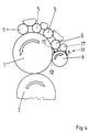
- the application roller 6 is in the first for the wet offset mode of operation Contact zone 12 in contact with the plate cylinder 1.
- the Applicator roller 6 assigned a bridge roller 18 in contact, optionally separately with the application roller 6 or with the in the direction of rotation of the plate cylinder 1 first inking roller 5 of the inking unit 4 and the application roller 6 in contact is.
- At least one plating device 11 is in the direction of rotation of the application roller 6 after the first contact zone 12 and / or after the contact zone of Bridge roller 18 and applicator roller 6 can be turned on / off on the lateral surface of the applicator roller 6.
- the applicator roller 6 with at least one Plating device 11 shown wherein the plating device 11 in Fig. 6 by a plating element 13 with holder 14, which extends across the roll width and storage 15 is formed.
- Fig. 7 is another about the Platen 11 extending roller width shown, the double arranged plating elements 13.
- the cladding elements 13 overlap themselves in a defined area and are preferably in a common area Bracket 14 and a bearing 15 added.
- the free ends of the Plating elements 13 end in different tangents or secants Points on the outer surface of the applicator roller 6.
- the plating device 11 is at an angle of inclination arranged adjustable.
- FIGS. 6, 7 show that regardless of the mode of operation in Direction of rotation of the application roller 6 after the contact zone 12 with the inked Plate cylinder 1 (in which there is a color break or a color split) on the
- the lateral surface of the application roller 6 has an uneven surface topography 19 in Form of color tips, color crests and color valleys is present.
- Applicator roller 6 the plating device 11 connected downstream in the direction of rotation, see above becomes the uneven surface topography - without shearing of the Plating device 11 - leveled cohesively and there is a flat Surface topography 20 of the ink on the applicator roller 6 before.
- Each plating device 11 is in the direction of rotation of the applicator roller 6 after Contact point 12 to improve the cohesion of the color preferably with a uniform surface pressure and the outer surface of the application roller 6 assigned.
- The is independent of the operating modes wet offset or dry offset Applicator roller 6 always optionally with a peripheral speed of Plate cylinder 1 same or different peripheral speed drivable.
Landscapes
- Engineering & Computer Science (AREA)
- Mechanical Engineering (AREA)
- Inking, Control Or Cleaning Of Printing Machines (AREA)
- Rotary Presses (AREA)
Abstract
Description
Es wurde gefunden, dass beim Nassoffsetdruck mit der Auftragwalze und wenigstens einer zugeordneten Plattiereinrichtung die Feuchtmittelzufuhr vom Feuchtduktor her zur Auftragwalze verringert werden kann und auch der Einsatz von Alkohol reduziert werden kann.
Es ist weiterhin vorteilhaft, dass die Auftragwalze zum Plattenzylinder mit wahlweise gleicher oder ungleicher Umfangsgeschwindigkeit antreibbar ist und dass die Plattiereinrichtung eine Formänderung der Farbspitzen, Farbkuppen und Farbtäler nach einem Abriss bzw. einer Farbspaltung hin zu einer ebenen Oberflächentopographie bewirkt. Bei einer derartigen Formänderung (plastischen Formänderung) der Farbe von einer unebenen Oberflächentopographie hin zu einer ebenen Oberflächentopographie auf der Mantelfläche der Auftragwalze gleiten die Farbspitzen, Farbkuppen in die Farbtäler. Es erfolgen somit innerhalb der Farbschicht des Farbgefüges auf der Auftragwalze Abgleitvorgänge, die die plastische Formgebung - ohne Abscherwirkung der Farbe - bewirken, so dass eine ebene Oberflächentopographie in einer definierten Schichtdicke erzielbar ist.
- Fig. 1
- ein Offsetdruckwerk mit einem Farbwerk und einem Feuchtwerk (Nassoffsetbetrieb),
- Fig. 2
- ein erstes Offsetdruckwerk für den Trockenoffsetbetrieb,
- Fig. 3
- ein zweites Offsetdruckwerk für den Trockenoffsetbetrieb,
- Fig. 4
- eine Weiterbildung der Figuren 2 und 3,
- Fig. 5
- eine Weiterbildung von Figur 1,
- Fig. 6
- eine Auftragwalze mit einer Plattiereinrichtung mit
einem
Plattierelement, - Fig. 7
- eine Auftragwalze mit einer Plattiereinrichtung mit doppelt angeordneten Plattierelementen.
Bevorzugt ist im Nassoffsetbetrieb wenigstens eine Plattiereinrichtung 11 in Drehrichtung der Auftragwalze 6 vor der in der zweiten Kontaktzone 16 mit der Auftragwalze 6 in Funktionsverbindung stehenden Feuchtmittelzuführung 7 - 9 angeordnet.
In einer Weiterbildung ist in Drehrichtung der Auftragwalze 6 nach der zweiten Kontaktzone 16 und vor der ersten Kontaktzone 12 eine weitere (baugleiche) Plattiereinrichtung 11 an die Mantelfläche der Auftragwalze 6 an- und abstellbar angeordnet.
In der Betreibweise für den Nass-Offset ist zumindest die vor der Kontaktzone 16 angeordnete Plattiereinrichtung 11 changierbar antreibbar.
Richtung tangentenförmig oder sekantenförmig an die Mantelfläche der Auftragwalze 6 an- und abstellbar angeordnet. Bevorzugt ist dabei jede Plattiereinrichtung 11 mittels einer Kraft F, beispielsweise von einer Druckfeder aufgebracht, an die Mantelfläche der Auftragwalze 6 anstellbar. Weiterhin bevorzugt ist mittels jeder Plattiereinrichtung 11 eine gleichmäßige Flächenpressung über die Breite der Auftragwalze 6 bzw. die unebene Oberflächentopographie der Farbe aufbringbar.
In einer weiteren Ausbildung endet das freie Ende des bevorzugt einstellbaren Plattierelements 13 in einem geringfügigen Abstand zur Mantelfläche der Auftragwalze 6. Dabei ist der Abstand derart, dass ein Einebnen einer unebenen Oberflächentopographie 19 realisierbar ist.
- 1
- Plattenzylinder
- 2
- Gummituchzylinder
- 3
- Feuchtwerk
- 4
- Farbwerk
- 5
- Farbauftragwalze
- 6
- Auftragwalze
- 7
- Feuchtduktor
- 8
- Dosierwalze
- 9
- Feuchtmittelbehälter
- 10
- Trennstelle
- 11
- Plattiereinrichtung
- 12
- 1. Kontaktzone
- 13
- Plattierelement
- 14
- Halterung
- 15
- Lagerung
- 16
- 2. Kontaktzone
- 17
- Brückenwalze (Trockenoffset)
- 18
- Brückenwalze (Nass-Offset)
- 19
- unebene Oberflächentopographie
- 20
- ebene Oberflächentopographie
- F
- Kraft
Claims (10)
- Offsetdruckwerk für eine Druckmaschine, mit einem eine Druckform tragenden Plattenzylinder, der mit an- und abstellbaren Farbauftragwalzen eines Farbwerkes und einem Feuchtwerk mit zumindest einer Feuchtmittelzuführeinrichtung und einer eine Kontaktzone mit dem Plattenzylinder bildenden Auftragwalze in Funktionsverbindung ist,
dadurch gekennzeichnet, dass in Drehrichtung der Auftragwalze (6) nach der ersten Kontaktzone (12) mit dem Plattenzylinder (1) zumindest eine Plattiereinrichtung (11) an- und abstellbar an die Mantelfläche der Auftragwalze (6) angeordnet ist und dass die Auftragwalze (6) wahlweise mit einer zur Umfangsgeschwindigkeit des Plattenzylinders (1) gleichen oder abweichenden Umfangsgeschwindigkeit antreibbar ist. - Offsetdruckwerk für eine Druckmaschine, mit einem eine Druckform tragenden Plattenzylinder, der mit an- und abstellbaren Farbauftragwalzen eines Farbwerkes und einem Feuchtwerk mit zumindest einer Feuchtmittelzuführeinrichtung und einer eine Kontaktzone mit dem Plattenzylinder bildenden Auftragwalze in Funktionsverbindung ist,
dadurch gekennzeichnet, dass in Drehrichtung der Auftragwalze (6) nach der ersten Kontaktzone (12) mit dem Plattenzylinder (1) zumindest eine Plattiereinrichtung (11) an- und abstellbar an die Mantelfläche der Auftragwalze (6) angeordnet ist und dass die Auftragwalze (6) wahlweise mit einer zur Umfangsgeschwindigkeit des Plattenzylinders (1) gleichen oder abweichenden Umfangsgeschwindigkeit antreibbar und bei abgeschalteter Feuchtmittelzuführung in der ersten Kontaktzone (12) an den Plattenzylinder (1) angestellt ist. - Offsetdruckwerk für eine Druckmaschine, mit einem eine Druckform für den feuchtmittelfreien Offsetdruck tragenden Plattenzylinder, der mit an- und abstellbaren Farbauftragwalzen eines Farbwerkes und einer von den Farbauftragwalzen unabhängigen, eine Kontaktzone mit dem Plattenzylinder bildenden Auftragwalze in Funktionsverbindung ist,
dadurch gekennzeichnet, dass in Drehrichtung der Auftragwalze (6) nach der ersten Kontaktzone (12) mit dem Plattenzylinder (1) zumindest eine Plattiereinrichtung (11) an- und abstellbar an die Mantelfläche der Auftragwalze (6) angeordnet ist und dass die Auftragwalze (6) wahlweise mit einer zur Umfangsgeschwindigkeit des Plattenzylinders (1) gleichen oder abweichenden Umfangsgeschwindigkeit antreibbar ist, wobei die Auftragwalze (6) in Drehrichtung des Plattenzylinders (1) den Farbauftragwalzen (5) vorgeordnet ist. - Offsetdruckwerk nach Anspruch 1 oder 2 oder 3,
dadurch gekennzeichnet, dass die Plattiereinrichtung (11) mit einem axial verreibenden Changierantrieb gekoppelt sind. - Offsetdruckwerk nach wenigstens Anspruch 1 oder 2 oder 3,
dadurch gekennzeichnet, dass die Plattiereinrichtung (11) in Drehrichtung der Auftragwalze (6) in ihrer Richtung tangentenförmig oder sekantenförmig an die Mantelfläche der Auftragwalze (6) anstellbar angeordnet ist. - Offsetdruckwerk nach wenigstens Anspruch 1 oder 2 oder 3,
dadurch gekennzeichnet, dass die Plattiereinrichtung (11) in ihrem Neigungswinkel zur Mantelfläche der Auftragwalze (6) einstellbar ist. - Offsetdruckwerk nach wenigstens Anspruch 1 oder 2 oder 3,
dadurch gekennzeichnet, dass mittels der Plattiereinrichtung (11) eine gleichmäßige Flächenpressung über die axiale Breite der Auftragwalze (6) aufbringbar ist. - Offsetdruckwerk nach wenigstens Anspruch 1 oder 2 oder 3,
dadurch gekennzeichnet, dass die Plattiereinrichtung (11) in Drehrichtung der Auftragwalze (6) ein Plattierelement (13) aufweist, welches sich über die gesamte Walzenbreite erstreckt und in einer Halterung (14) lösbar angeordnet ist. - Offsetdruckwerk nach wenigstens Anspruch 1 oder 2 oder 3 und 8,
dadurch gekennzeichnet, dass die Halterung (14) in einer beidseitigen Lagerung (15) angeordnet ist. - Offsetdruckwerk nach wenigstens Anspruch 1 oder 2 oder 3 und 8,
dadurch gekennzeichnet, dass ein freies Ende des Plattierelementes (13) tangentenförmig oder sekantenförmig an der Mantelfläche der Auftragwalze (6) endet.
Applications Claiming Priority (2)
| Application Number | Priority Date | Filing Date | Title |
|---|---|---|---|
| DE10020227 | 2000-04-26 | ||
| DE10020227A DE10020227B4 (de) | 2000-04-26 | 2000-04-26 | Offsetdruckwerk für eine Druckmaschine |
Publications (3)
| Publication Number | Publication Date |
|---|---|
| EP1149696A2 true EP1149696A2 (de) | 2001-10-31 |
| EP1149696A3 EP1149696A3 (de) | 2002-11-27 |
| EP1149696B1 EP1149696B1 (de) | 2010-08-04 |
Family
ID=7639872
Family Applications (1)
| Application Number | Title | Priority Date | Filing Date |
|---|---|---|---|
| EP01108985A Expired - Lifetime EP1149696B1 (de) | 2000-04-26 | 2001-04-11 | Offsetdruckwerk für eine Druckmaschine |
Country Status (3)
| Country | Link |
|---|---|
| EP (1) | EP1149696B1 (de) |
| AT (1) | ATE476294T1 (de) |
| DE (2) | DE10020227B4 (de) |
Cited By (2)
| Publication number | Priority date | Publication date | Assignee | Title |
|---|---|---|---|---|
| DE102007001669B3 (de) * | 2007-01-11 | 2007-12-06 | Koenig & Bauer Aktiengesellschaft | Feuchtwerk für Offsetdruckmaschine |
| DE102024106147A1 (de) * | 2024-03-04 | 2025-09-04 | Koenig & Bauer Ag | Druckwerk und Verfahren zur Positionierung von Bestandteilen eines Druckwerks |
Citations (3)
| Publication number | Priority date | Publication date | Assignee | Title |
|---|---|---|---|---|
| DE3843473A1 (de) | 1988-12-23 | 1990-07-12 | Kotterer Grafotec | Feuchtwerk fuer offsetdruckmaschinen |
| DE4404989C2 (de) | 1994-02-17 | 1995-11-30 | Roland Man Druckmasch | Offsetdruckvorrichtung |
| DE4423286A1 (de) | 1994-07-02 | 1996-01-04 | Heidelberger Druckmasch Ag | Druckwerk für eine Rotationsoffsetdruckmaschine |
Family Cites Families (8)
| Publication number | Priority date | Publication date | Assignee | Title |
|---|---|---|---|---|
| DE2948486C2 (de) * | 1979-12-01 | 1981-12-24 | M.A.N.- Roland Druckmaschinen AG, 6050 Offenbach | Farb- und Feuchtwerk für eine Rotationsoffsetdruckmaschine |
| DE3308067C1 (de) * | 1983-03-08 | 1984-09-13 | M.A.N.- Roland Druckmaschinen AG, 6050 Offenbach | Fluessigkeitszufuehrvorrichtung fuer Farbe und Feuchtfluessigkeit einer Rotationsflachdruckmaschine |
| US4724764B1 (en) * | 1983-05-11 | 1994-09-20 | Baldwin Technology Corp | Dampening system |
| JPS59212268A (ja) * | 1983-05-11 | 1984-12-01 | ボ−ルドウイン・テクノロジイ・コ−ポレイシヨン | 平版印刷機における給湿装置及び方法 |
| GB2151186B (en) * | 1983-12-12 | 1987-09-09 | Baldwin Technology Corp | Dampening system |
| DD274003A1 (de) * | 1988-07-11 | 1989-12-06 | Polygraph Leipzig | Rakeleinrichtung fuer offsetdruckmaschinen |
| DE19529205C2 (de) * | 1995-08-09 | 1997-08-14 | Roland Man Druckmasch | Feuchtwerk für eine Offsetdruckmaschine |
| DE19548287C2 (de) * | 1995-12-22 | 2000-01-13 | Heidelberger Druckmasch Ag | Druckwerk für eine Rotationsoffsetdruckmaschine |
-
2000
- 2000-04-26 DE DE10020227A patent/DE10020227B4/de not_active Expired - Fee Related
-
2001
- 2001-04-11 EP EP01108985A patent/EP1149696B1/de not_active Expired - Lifetime
- 2001-04-11 AT AT01108985T patent/ATE476294T1/de active
- 2001-04-11 DE DE50115577T patent/DE50115577D1/de not_active Expired - Lifetime
Patent Citations (3)
| Publication number | Priority date | Publication date | Assignee | Title |
|---|---|---|---|---|
| DE3843473A1 (de) | 1988-12-23 | 1990-07-12 | Kotterer Grafotec | Feuchtwerk fuer offsetdruckmaschinen |
| DE4404989C2 (de) | 1994-02-17 | 1995-11-30 | Roland Man Druckmasch | Offsetdruckvorrichtung |
| DE4423286A1 (de) | 1994-07-02 | 1996-01-04 | Heidelberger Druckmasch Ag | Druckwerk für eine Rotationsoffsetdruckmaschine |
Cited By (3)
| Publication number | Priority date | Publication date | Assignee | Title |
|---|---|---|---|---|
| DE102007001669B3 (de) * | 2007-01-11 | 2007-12-06 | Koenig & Bauer Aktiengesellschaft | Feuchtwerk für Offsetdruckmaschine |
| DE102007001669C5 (de) * | 2007-01-11 | 2009-08-27 | Koenig & Bauer Aktiengesellschaft | Feuchtwerk für Offsetdruckmaschine |
| DE102024106147A1 (de) * | 2024-03-04 | 2025-09-04 | Koenig & Bauer Ag | Druckwerk und Verfahren zur Positionierung von Bestandteilen eines Druckwerks |
Also Published As
| Publication number | Publication date |
|---|---|
| EP1149696A3 (de) | 2002-11-27 |
| EP1149696B1 (de) | 2010-08-04 |
| DE10020227B4 (de) | 2004-07-15 |
| ATE476294T1 (de) | 2010-08-15 |
| DE10020227A1 (de) | 2001-10-31 |
| DE50115577D1 (de) | 2010-09-16 |
Similar Documents
| Publication | Publication Date | Title |
|---|---|---|
| DE4224235C5 (de) | Breiten-Einstellvorrichtung für eine Papierbahn, sowie damit ausgestattete Rotationspresse | |
| EP0293586A2 (de) | Geteilter Farbkasten für eine Flexodruckmaschine | |
| DE4327646C5 (de) | Breiten-Einstellverfahren für eine Papierbahn sowie damit ausgerüstete lithographische Rotationspresse | |
| EP1013418B1 (de) | Farbwerk | |
| DE4439144C2 (de) | Farbwerk einer Rotationsoffsetdruckmaschine | |
| EP0749368A1 (de) | Mehrfarbenrollenrotationsdruckmaschine für akzidenzdruck | |
| DE19911568A1 (de) | Verfahren zum Einfeuchten einer Flachdruckform und Feuchtwerk einer Flachdruckmaschine | |
| EP0518892B1 (de) | Kurzfarbwerk für eine rollenrotationsdruckmaschine | |
| DE69816705T2 (de) | Muffenförmiges Drucktuch sowie Druckmaschine unter Verwendung desselben | |
| DE60020252T2 (de) | Verfahren zum betreiben einer druckeinheit und druckeinheit für eine offset-druckmaschine | |
| AT397635B (de) | Dosiervorrichtung eines farbwerkes einer druckmaschine | |
| EP0761432B2 (de) | Feuchtwerk für eine Offsetdruckmaschine | |
| EP0085752B1 (de) | Druckwerk für eine Offsetrotationsdruckmaschine | |
| EP1149696A2 (de) | Offsetdruckwerk für eine Druckmaschine | |
| DE29706932U1 (de) | Feuchtwerk für eine Offsetdruckmaschine | |
| EP1278637B1 (de) | Dosiersystem zum einfärben von walzen in einer druckmaschine | |
| EP0761431B1 (de) | Feuchtwerk für eine Offsetdruckmaschine | |
| DE19645169C2 (de) | Verfahren zur Reinigung von Zylindern und Walzen in einer Druckmaschine | |
| EP1698463B1 (de) | Feuchtwerk für eine Offsetdruckeinheit einer Druckmaschine | |
| EP1442884B1 (de) | Verfahren für einen stabilen Maschinenlauf an Druckeinheiten einer Rotationsdruckmaschine für den Betrieb mit teilbreitem Bedruckstoff | |
| EP1149695B1 (de) | Feuchtwerk für eine Offsetdruckmaschine | |
| DE4101797A1 (de) | Kurzfarbwerk fuer eine rollenrotationsdruckmaschine | |
| DE4345603B4 (de) | Rotationsdruckmaschine und Bahnbreiten-Einstellverfahren für ein Drucksystem | |
| DE10338193B4 (de) | Eindruckwerksgruppe in einer Gummituch-Gummituch-Konfiguration | |
| DE10222060A1 (de) | Bogenführungstrommel in einer Druckmaschine |
Legal Events
| Date | Code | Title | Description |
|---|---|---|---|
| PUAI | Public reference made under article 153(3) epc to a published international application that has entered the european phase |
Free format text: ORIGINAL CODE: 0009012 |
|
| AK | Designated contracting states |
Kind code of ref document: A2 Designated state(s): AT BE CH CY DE DK ES FI FR GB GR IE IT LI LU MC NL PT SE TR |
|
| AX | Request for extension of the european patent |
Free format text: AL;LT;LV;MK;RO;SI |
|
| PUAL | Search report despatched |
Free format text: ORIGINAL CODE: 0009013 |
|
| AK | Designated contracting states |
Kind code of ref document: A3 Designated state(s): AT BE CH CY DE DK ES FI FR GB GR IE IT LI LU MC NL PT SE TR |
|
| AX | Request for extension of the european patent |
Free format text: AL;LT;LV;MK;RO;SI |
|
| 17P | Request for examination filed |
Effective date: 20021016 |
|
| AKX | Designation fees paid |
Designated state(s): AT BE CH CY DE DK ES FI FR GB GR IE IT LI LU MC NL PT SE TR |
|
| RAP1 | Party data changed (applicant data changed or rights of an application transferred) |
Owner name: MANROLAND AG |
|
| 17Q | First examination report despatched |
Effective date: 20090303 |
|
| GRAP | Despatch of communication of intention to grant a patent |
Free format text: ORIGINAL CODE: EPIDOSNIGR1 |
|
| GRAS | Grant fee paid |
Free format text: ORIGINAL CODE: EPIDOSNIGR3 |
|
| GRAA | (expected) grant |
Free format text: ORIGINAL CODE: 0009210 |
|
| AK | Designated contracting states |
Kind code of ref document: B1 Designated state(s): AT BE CH CY DE DK ES FI FR GB GR IE IT LI LU MC NL PT SE TR |
|
| REG | Reference to a national code |
Ref country code: GB Ref legal event code: FG4D Free format text: NOT ENGLISH |
|
| REG | Reference to a national code |
Ref country code: CH Ref legal event code: EP |
|
| REG | Reference to a national code |
Ref country code: IE Ref legal event code: FG4D Free format text: LANGUAGE OF EP DOCUMENT: GERMAN |
|
| REF | Corresponds to: |
Ref document number: 50115577 Country of ref document: DE Date of ref document: 20100916 Kind code of ref document: P |
|
| REG | Reference to a national code |
Ref country code: NL Ref legal event code: VDEP Effective date: 20100804 |
|
| PG25 | Lapsed in a contracting state [announced via postgrant information from national office to epo] |
Ref country code: NL Free format text: LAPSE BECAUSE OF FAILURE TO SUBMIT A TRANSLATION OF THE DESCRIPTION OR TO PAY THE FEE WITHIN THE PRESCRIBED TIME-LIMIT Effective date: 20100804 Ref country code: FI Free format text: LAPSE BECAUSE OF FAILURE TO SUBMIT A TRANSLATION OF THE DESCRIPTION OR TO PAY THE FEE WITHIN THE PRESCRIBED TIME-LIMIT Effective date: 20100804 |
|
| PG25 | Lapsed in a contracting state [announced via postgrant information from national office to epo] |
Ref country code: CY Free format text: LAPSE BECAUSE OF FAILURE TO SUBMIT A TRANSLATION OF THE DESCRIPTION OR TO PAY THE FEE WITHIN THE PRESCRIBED TIME-LIMIT Effective date: 20100804 Ref country code: PT Free format text: LAPSE BECAUSE OF FAILURE TO SUBMIT A TRANSLATION OF THE DESCRIPTION OR TO PAY THE FEE WITHIN THE PRESCRIBED TIME-LIMIT Effective date: 20101206 |
|
| REG | Reference to a national code |
Ref country code: IE Ref legal event code: FD4D |
|
| PG25 | Lapsed in a contracting state [announced via postgrant information from national office to epo] |
Ref country code: GR Free format text: LAPSE BECAUSE OF FAILURE TO SUBMIT A TRANSLATION OF THE DESCRIPTION OR TO PAY THE FEE WITHIN THE PRESCRIBED TIME-LIMIT Effective date: 20101105 Ref country code: SE Free format text: LAPSE BECAUSE OF FAILURE TO SUBMIT A TRANSLATION OF THE DESCRIPTION OR TO PAY THE FEE WITHIN THE PRESCRIBED TIME-LIMIT Effective date: 20100804 |
|
| PG25 | Lapsed in a contracting state [announced via postgrant information from national office to epo] |
Ref country code: DK Free format text: LAPSE BECAUSE OF FAILURE TO SUBMIT A TRANSLATION OF THE DESCRIPTION OR TO PAY THE FEE WITHIN THE PRESCRIBED TIME-LIMIT Effective date: 20100804 Ref country code: IE Free format text: LAPSE BECAUSE OF FAILURE TO SUBMIT A TRANSLATION OF THE DESCRIPTION OR TO PAY THE FEE WITHIN THE PRESCRIBED TIME-LIMIT Effective date: 20100804 |
|
| PG25 | Lapsed in a contracting state [announced via postgrant information from national office to epo] |
Ref country code: IT Free format text: LAPSE BECAUSE OF FAILURE TO SUBMIT A TRANSLATION OF THE DESCRIPTION OR TO PAY THE FEE WITHIN THE PRESCRIBED TIME-LIMIT Effective date: 20100804 |
|
| PLBE | No opposition filed within time limit |
Free format text: ORIGINAL CODE: 0009261 |
|
| STAA | Information on the status of an ep patent application or granted ep patent |
Free format text: STATUS: NO OPPOSITION FILED WITHIN TIME LIMIT |
|
| PG25 | Lapsed in a contracting state [announced via postgrant information from national office to epo] |
Ref country code: ES Free format text: LAPSE BECAUSE OF FAILURE TO SUBMIT A TRANSLATION OF THE DESCRIPTION OR TO PAY THE FEE WITHIN THE PRESCRIBED TIME-LIMIT Effective date: 20101115 |
|
| 26N | No opposition filed |
Effective date: 20110506 |
|
| PGFP | Annual fee paid to national office [announced via postgrant information from national office to epo] |
Ref country code: DE Payment date: 20110421 Year of fee payment: 11 |
|
| REG | Reference to a national code |
Ref country code: DE Ref legal event code: R097 Ref document number: 50115577 Country of ref document: DE Effective date: 20110506 |
|
| BERE | Be: lapsed |
Owner name: MANROLAND A.G. Effective date: 20110430 |
|
| PG25 | Lapsed in a contracting state [announced via postgrant information from national office to epo] |
Ref country code: MC Free format text: LAPSE BECAUSE OF NON-PAYMENT OF DUE FEES Effective date: 20110430 |
|
| REG | Reference to a national code |
Ref country code: CH Ref legal event code: PL |
|
| GBPC | Gb: european patent ceased through non-payment of renewal fee |
Effective date: 20110411 |
|
| REG | Reference to a national code |
Ref country code: FR Ref legal event code: ST Effective date: 20111230 |
|
| PG25 | Lapsed in a contracting state [announced via postgrant information from national office to epo] |
Ref country code: BE Free format text: LAPSE BECAUSE OF NON-PAYMENT OF DUE FEES Effective date: 20110430 Ref country code: FR Free format text: LAPSE BECAUSE OF NON-PAYMENT OF DUE FEES Effective date: 20110502 Ref country code: CH Free format text: LAPSE BECAUSE OF NON-PAYMENT OF DUE FEES Effective date: 20110430 Ref country code: LI Free format text: LAPSE BECAUSE OF NON-PAYMENT OF DUE FEES Effective date: 20110430 |
|
| PG25 | Lapsed in a contracting state [announced via postgrant information from national office to epo] |
Ref country code: GB Free format text: LAPSE BECAUSE OF NON-PAYMENT OF DUE FEES Effective date: 20110411 |
|
| REG | Reference to a national code |
Ref country code: DE Ref legal event code: R081 Ref document number: 50115577 Country of ref document: DE Owner name: MANROLAND SHEETFED GMBH, DE Free format text: FORMER OWNER: MANROLAND AG, 63075 OFFENBACH, DE Effective date: 20120509 |
|
| REG | Reference to a national code |
Ref country code: AT Ref legal event code: MM01 Ref document number: 476294 Country of ref document: AT Kind code of ref document: T Effective date: 20110411 |
|
| PG25 | Lapsed in a contracting state [announced via postgrant information from national office to epo] |
Ref country code: AT Free format text: LAPSE BECAUSE OF NON-PAYMENT OF DUE FEES Effective date: 20110411 |
|
| REG | Reference to a national code |
Ref country code: DE Ref legal event code: R119 Ref document number: 50115577 Country of ref document: DE Effective date: 20121101 |
|
| PG25 | Lapsed in a contracting state [announced via postgrant information from national office to epo] |
Ref country code: LU Free format text: LAPSE BECAUSE OF NON-PAYMENT OF DUE FEES Effective date: 20110411 |
|
| PG25 | Lapsed in a contracting state [announced via postgrant information from national office to epo] |
Ref country code: TR Free format text: LAPSE BECAUSE OF FAILURE TO SUBMIT A TRANSLATION OF THE DESCRIPTION OR TO PAY THE FEE WITHIN THE PRESCRIBED TIME-LIMIT Effective date: 20100804 |
|
| PG25 | Lapsed in a contracting state [announced via postgrant information from national office to epo] |
Ref country code: DE Free format text: LAPSE BECAUSE OF NON-PAYMENT OF DUE FEES Effective date: 20121101 |