EP1149770B1 - Pistolet de fixation d'épingles en boucle - Google Patents
Pistolet de fixation d'épingles en boucle Download PDFInfo
- Publication number
- EP1149770B1 EP1149770B1 EP01303864A EP01303864A EP1149770B1 EP 1149770 B1 EP1149770 B1 EP 1149770B1 EP 01303864 A EP01303864 A EP 01303864A EP 01303864 A EP01303864 A EP 01303864A EP 1149770 B1 EP1149770 B1 EP 1149770B1
- Authority
- EP
- European Patent Office
- Prior art keywords
- pin
- loop
- section
- connecting device
- feeding
- Prior art date
- Legal status (The legal status is an assumption and is not a legal conclusion. Google has not performed a legal analysis and makes no representation as to the accuracy of the status listed.)
- Expired - Lifetime
Links
Images




Classifications
-
- B—PERFORMING OPERATIONS; TRANSPORTING
- B65—CONVEYING; PACKING; STORING; HANDLING THIN OR FILAMENTARY MATERIAL
- B65C—LABELLING OR TAGGING MACHINES, APPARATUS, OR PROCESSES
- B65C7/00—Affixing tags
- B65C7/003—Affixing tags using paddle-shaped plastic pins
- B65C7/005—Portable tools
-
- B—PERFORMING OPERATIONS; TRANSPORTING
- B65—CONVEYING; PACKING; STORING; HANDLING THIN OR FILAMENTARY MATERIAL
- B65C—LABELLING OR TAGGING MACHINES, APPARATUS, OR PROCESSES
- B65C7/00—Affixing tags
-
- Y—GENERAL TAGGING OF NEW TECHNOLOGICAL DEVELOPMENTS; GENERAL TAGGING OF CROSS-SECTIONAL TECHNOLOGIES SPANNING OVER SEVERAL SECTIONS OF THE IPC; TECHNICAL SUBJECTS COVERED BY FORMER USPC CROSS-REFERENCE ART COLLECTIONS [XRACs] AND DIGESTS
- Y10—TECHNICAL SUBJECTS COVERED BY FORMER USPC
- Y10T—TECHNICAL SUBJECTS COVERED BY FORMER US CLASSIFICATION
- Y10T29/00—Metal working
- Y10T29/53—Means to assemble or disassemble
- Y10T29/53478—Means to assemble or disassemble with magazine supply
- Y10T29/53487—Assembling means comprising hand-manipulatable implement
Definitions
- the present invention relates to a loop pin connecting device for connecting clothes, socks, etc. or attaching tags such as brand labels, price tags, material description, instructions, etc. by inserting a latching piece to the product.
- the conventional loop pin connecting device forms a loop by inserting an inserting head section into a socket section held to the head end of the guiding member formed nearly semicircularly by successively feeding relevant loop pins from those temporarily fastening integrally with a joining bar a plurality of loop pins comprising an inserting head section and a socket section by grasping a hand-gun type lever. And the guiding member that holds the socket section was arranged horizontally.
- US 6,026,544, corresponding to the preamble of claim 1, discloses a fastener attaching tool that includes a hollow, slotted needle insertable through a hole of a tag.
- the hollow, slotted needle is shaped to include a detent on its exterior. The detent is adapted to engage the tag so that the tag can be retained securely on the needle while a fastener is inserted through the hole of the tag.
- the tool may include an arm assembly, the arm assembly being shaped to define a feed channel through which a socket portion of a fastener is adapted to travel.
- the channel is shaped complementary to the socket to maximise rotational alignment of the socket with an incoming plug.
- the arm assembly may be provided with a stop that is shaped to engage the rear end of the socket portion of a fastener so as to maximise translational alignment of the socket with an incoming plug.
- the present invention basically adopts the configuration recited as follows in order to solve the above-mentioned problems.
- the loop pin connecting device bends the guide member for guiding the head end section of the second feeding pin that presses out the socket section of the loop pin and at the same time lowers its head end to the position of the first feeding pin arranged with the height and horizontal position varied, and mounting the loop pins with the horizontal height position varied can prevent entangling of the filament section.
- allowing the cam member to change the travel speed of the first pin holder section in the vicinity of the dead end section can prevent cracks from being generated when the inserting head section is inserted into the loop pin socket section.
- FIG. I is a side view showing the internal structure of a loop pin connecting device according to the present invention.
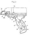
- the loop pin connecting device 10 according to the present invention comprises a grip lever 12 rotatably pivoted to the grip section 11 of a main body portion of the device, a driving arm 13 swung by the grip lever 12, the first pin holder section 15 that linearly travels on the first guide rail 14 by the driving arm 13, the first feeding pin 16 fixed to the first pin holder section 15, the second pin holder section 18 that linearly travels on the second guide rail 17 by the driving arm 13, the second feeding pin 19 comprising flexible member whose base end is fixed to the second pin holder section 18, and a guide member 20 for guiding a tip end section of the second feeding pin 19, wherein the guide member 20 is bent and its tip end is lowered with inclination to a position at which a tip of the first feeding pin 16 would be reached and which being three
- the second feeding pin 19 comprises a member with flexibility such as densely wound coil springs, etc.
- the grip lever 12 as shown in FIG. 1, is rotatably pivoted to the pin 21 erectly built to the device proper and at the same time, on the inside surface, the first cam 22 that comes in contact with the base end section of the driving arm 13 is formed.
- the travel speed of the first feeding pin 16 is able to be changed.
- the first cam 22 is formed in such a profile to come in contact with the roller 24 constantly at right angles even when the grip lever 12 rotates around the pin 21.
- the driving arm 13 is rotatably supported to the support shaft 23 erectly built to the nearly center inside surface of the grip section 11, with the base end section 13a bent at right angles.
- a roller 24 is rotatably mounted to the base end section 13a.
- a spring member 25 with one end fixed to the grip section is tightly affixed. By this spring member 25, the driving arm 13 is energized to rotate clockwise. Consequently, the roller 24 at the base end section is energized in the direction to constantly come in contact with the first cam 22.
- the driving arm 13 is equipped with the second cam 26 for driving the first pin holder section 15.
- the second cam 26 has curved sections 26a, 26b nearly symmetrically curved to both sides, as well as a pointed arm 26c at the top end.
- a hole 13c is formed, to which a link member 27 for linking the second pin holder section 18 is rotatably connected.
- the link member 27 is connected to the head end section of the driving arm 13 by an elongated hole.
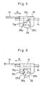
- FIGS. 5, 6 are explanatory drawings showing the relation of the first pin holder section 15 to the second cam 26.
- FIG. 5 shows the condition in which the grip lever 12 is not grasped and the driving arm 13 is energized to rotate clockwise by the spring member 25 (see FIG. I ) .
- the first pin holder section 15 is moved in the right direction in the figure by the curved section 26b of the section cam 26, and the first feeding pin 16 also retracts to the depths.
- the second cam 26 is inserted into the recessed groove at the center of the first pin holder section 15.
- FIG. 6 shows the condition in which the grip lever 12 is grasped and the driving arm 13 is rotated counterclockwise against the spring member 25 (see FIG. 2).
- the first pin holder section 15 is moved to the left direction in the drawing by the pointed head section 26c of the second cam 26, and the first feeding pin 16 is also protruded to the top end.
- the relation of the first pin holder section 15 to the second cam 26 is that the at first the recessed groove side wall of the first pin holder section comes in contact with the curved section 26a, but as the driving arm 13 rotates successively, the notched section 26d of the second cam comes in contact, and the feed speed of the first pin holder section 15 temporarily reduces in the vicinity of the dead end.
- the pointed head section 26c falls into the small recessed section 15a formed on the recessed groove side wall, and the first pin holder section 15 is able to be held in this condition.
- the second pin holder section 18 is linked to the driving arm 13 via the link member 27, and is guided by the second guide rail 17 to carry out linear movement (see FIG. 3).
- the driving arm 13 rotates counterclockwise
- the link member 27 that has been pressing the second pin holder section 18 in the form of inverse V letter form rotates in a toggle form at the elongated hole section, and changes the travel speed of the second pin holder section 18 in the vicinity of the dead end section. That is, when the link member 27 rotates in the toggle form, the second pin holder section 18 scarcely moves.
- jumping of the second feeding pin 19 is able to be prevented. Consequently, the socket section is able to be held and fixed to the head end of the guide member 20.
- the socket section that has arrived at the head end of the guide member 20 in advance can be kept waited.
- the link member 27 connected to the head end rotates to advance the second pin holder section 18 along the second guide rail 17. Because the second pin holder section 18 is located still further from the rotation center of the driving arm 13, it advances at a speed faster than that of the first pin holder section 15. Because the distance in which the socket section 28a arrives at the head end position while passing through the guide member 20 is longer than that in which the inserting head section 28b advances straight, the moving stroke should be set longer accordingly. The moving timing of both should be set in such a manner that the socket section 28a arrives first and thereafter the inserting head section 28b arrives next to engage.
- the first feeding pin 16 has the advancing speed temporarily reduced in the vicinity of the dead end section where it protrudes by the structures of the second cam 26 and the first pin holder section 15 and at the same time latched at the protruding dead end section, it is possible to prevent cracks from being generated in the loop pin. Furthermore, because the feeding pin is latched in the protruded condition, the inserting head section is securely affixed to the socket section.
- the second pin holder section 18 is linked to the head end of the driving arm 13 via the link member 27, it rotates in the form of toggle at the section of hole 13c and stops the movement of the second pin holder section 18 at the dead end section. That is, when the link member 27 rotates around the hole 13c, the second pin holder section 18 scarcely advances. With this mechanism, jumping back of the second feeding pin 19 is able to be prevented, and the socket section 28a is able to be held and fixed to the head end of the guide member 20.
- a loop pin connecting device for connecting the inserting head section to the holder section of the loop pin having an inserting head section at one end section of a filament section and a holder section for receiving the inserting head section at its other end section
- the loop pin connecting device comprising the first feeding pin 16 for holding the inserting head section of the loop pin arranged at the predetermined first position, on a tip end section of said first feeding pin 16 and for moving, said inserting head section to the scheduled connection position of the inserting head section and the holder section, and the second feeding pin 19 for holding the holder section of the loop pin arranged at the predetermined second position on a tip end section of said second feeding pin 19 and for moving said holder section to said scheduled connection position, and the first and the second positions being located on the loop pin connecting device with a specified distance provided for each other, and the individual stroke lengths of the first feeding pin 16 and the second feeding pin 19 being established by one driving arm 13 rotatably installed by a grip section 11 mounted to a main body portion of the loop
- the stroke length of the second feeding pin 19 is set longer than the stroke length of the first feeding pin 16.
- the first engaging position in which the first feeding pin 16 directly or indirectly engages with the driving arm 13 differs from the second engaging position in which the second feeding pin 19 directly or indirectly engages with the driving arm 13, respectively.
- the distance between the position of rotation center axis of the driving arm 13 and the second engaging position is set longer than the distance between the position of rotation center axis and the first engagement position.
- the first position and the second position are separated each other by a specified distance in the horizontal direction, as well as separated each other by a specified distance in the vertical direction.
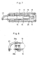
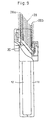
- the second feeding pin 19 is configured in such a manner that it is guided inside the guide member protruded in the form of curvature from the second position to the first position.
- the tip end section of the guide member in the form of curvature is arranged at the position intersecting the axis of the first feeding pin 16 and at the scheduled connection position of the inserting head section and the holder section of said loop pin.
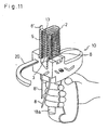
- loop pin gun a method for using the loop pin connecting device (hereinafter referred to as a loop pin gun), utilizing a unit of loop pins, in which a plurality of loop pins are parallely arranged and fastened to each other with connecting bars, will be explained hereunder.
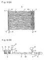
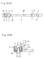
- each of the loop pins has a configuration as shown in Fig. 10(A) to Fig. 10(D), such that the loop pins comprise an insertion head 3 provided on one end portion 60 of a filament 2 and having an appropriate mating part 6 and a socket portion 5 provided on the other end 30 of the filament 2 and having a hole 4 provided with blocking blades 16 therein for irreversibly passing the insertion head 3.
- the loop pin 1 is so formed that the filament 2, the insertion head 3 and the socket portion 5 are integrally formed as one body.
- the appropriate mating part 6, which may be a step-like portion, for example, can fixedly engaged with the blocking blades 16 so that the insertion head 3 cannot move in the opposite direction to its insertion direction, thus preventing the insertion head 3 from being removed from the socket portion 5 easily.
- loop pin 1 Since the loop pin 1 is used to attach it to specific commercial goods to maintain a suitable tag or label on the filament 2, utilizing a mechanical operation, the above-mentioned loop pin gun 10 of the present invention can be used.
- a unit of loop pin 9 is desirably used.
- a plurality of the loop pins 1 are arranged in parallel to each other and are temporarily attached to a pair of connecting bars 8 and 8' with a weak connection link 11 and 11' which is easily cut by a suitable portion provided on the loop pin gun 10 so as to easily separate each one of the loop pins 1 from the connecting bars 8 and 8'.
- the connecting bar 8 is provided on or in the vicinity of the insertion head 3 while the connecting bar 8' is provided on or in the vicinity of the socket portion 5, respectively.
- the guiding passages 50 and 50' are connected to the insertion vertical grooves 32 and 32', respectively.
- the guiding passages 50 and 50' can be formed as a groove, a hollow pipe, a simple guide plate or guide ring or the like.
- a suitable feeding means for positively feeding the connecting bars 8 and 8', therethrough in response to the operation of the operation lever 18a may be provided along the line of guiding passages 50 and 50' or at a suitable position closer to the insertion vertical groove 32 and 32'.
- a roller or a gear roller which is positively rotate or a cam or a latch which is moved in a predetermined constant direction can be used for this purpose.
- the connecting bars 8 and 8' per se can be made of a flexible belt-like member or a film-like member each of which preferably has a small thickness.
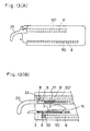
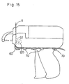
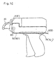
- the connecting bars 8 and 8' can be withdrawn from inside a main body of the loop pin gun 10 at a position bent by a suitable guide plate 60 so as to be guided to a rear portion of the loop pin 10 via several guide rings 70, for example, the guiding passages 50 and 50' of which are different from that as shown in Fig. 12 which is a tube-like member.
- a part of the guiding passage 50 (50'), for example, around a first one third of the whole length of the guiding passage 50 (50') is formed inside the main body of the gun and the remaining part thereof, for example, around the last two thirds thereof is formed on an external side wall of the gun so that the guiding passage 90 (90') comprises an open-type groove formed along the external side wall of the gun.
- the present invention adopts the configuration as described above, and since the loop pin group is able to be mounted to the device with the height position of the socket section and the inserting head section varied, respectively, entangling of the filament section is able to be prevented, and occurrence of jams is able to be impeded while it is in operation. Consequently, the working efficiency is able to be improved. In addition, since the width of the device is able to be reduced, the workability is increased.
Landscapes
- Labeling Devices (AREA)
- Portable Nailing Machines And Staplers (AREA)
- Sewing Machines And Sewing (AREA)
- Hand Tools For Fitting Together And Separating, Or Other Hand Tools (AREA)
- Basic Packing Technique (AREA)
- Buckles (AREA)
Claims (19)
- Dispositif de fixation d'épingles en boucle (10) pour relier les extrémités opposées d'une épingle en boucle, le dispositif comprenant :une poignée de préhension (12) raccordée de façon pivotante à une section de préhension (11) d'une partie de corps principal du dispositif (10) ;un bras d'entraínement (13) raccordé de façon pivotante à la section de préhension (11) et mis en prise de façon fonctionnelle avec la poignée de préhension (12) ;une section de support d'une première broche d'alimentation (15) montée sur un premier rail de guidage (14) et engagée de façon opérationnelle avec le bras d'entraínement (13) pour entraíner la section de support de la première broche d'alimentation (15) linéairement le long du premier rail de guidage ;une première broche d'alimentation (16) fixée à la section de support de la première broche d'alimentation (15) pour amener une première extrémité (28b) d'une épingle en boucle (28) qui doit être raccordée depuis une première section de montage sur la partie de corps principal du dispositif (10) à une position de raccordement au niveau de laquelle lesdites extrémités opposées de l'épingle en boucle doivent être raccordées l'une à l'autre ;une deuxième broche d'alimentation (19) comprenant un élément flexible allongé ayant une extrémité formant base et une extrémité formant pointe ;un élément de guidage courbe allongé (20) le long duquel l'extrémité formant pointe de la deuxième broche d'alimentation (19) est guidée pour déplacer une deuxième extrémité (28a) de l'épingle en boucle (28) depuis une extrémité formant base jusqu'à une extrémité formant pointe de l'élément de guidage (20) qui correspond à ladite position de raccordement ; caractérisé en ce que le dispositif comprend une section de support de la deuxième broche d'alimentation (18) montée sur un deuxième rail de guidage (17), la section de support de la deuxième broche d'alimentation (18) étant en prise de façon opérationnelle avec le bras d'entraínement (13) pour entraíner la section de support de la deuxième broche d'alimentation (18) linéairement le long du deuxième rail de guidage (17), l'extrémité formant base de l'élément flexible étant fixée à ladite section de support de la deuxième broche d'alimentation (18) ; et en ce que le deuxième rail de guidage (17) est globalement parallèle au premier rail de guidage (14) et se déplace horizontalement et verticalement par rapport à celui-ci lorsque le dispositif de fixation d'épingles en boucle est orienté dans une position verticale et que le premier rail de guidage est placé horizontalement de telle sorte que l'extrémité formant pointe de l'élément de guidage (20) est espacée en trois dimensions par rapport à la position de la deuxième broche d'alimentation (19).
- Dispositif de fixation d'épingles en boucle (10) selon la revendication 1, dans lequel le bras d'entraínement (13) entraíne la deuxième broche d'alimentation (19) de telle sorte qu'elle arrive à l'extrémité formant pointe de l'élément de guidage (20) avant la première broche d'alimentation (16).
- Dispositif de fixation d'épingles en boucle (10) selon la revendication 1 ou 2, dans lequel le bras d'entraínement (13) entraíne la section de support de la première broche d'alimentation (15) par l'intermédiaire d'un élément formant came (26) monté sur une partie du bras d'entraínement (13).
- Dispositif de fixation d'épingles en boucle (10) selon la revendication 3, dans lequel l'élément formant came (26) présente un profil de came qui fait varier la vitesse de déplacement de la section de support de la première broche d'alimentation (15) dans le voisinage d'une section formant cul de sac dudit premier rail de guidage (14).
- Dispositif de fixation d'épingles en boucle (10) selon la revendication 4, dans lequel le profil de came provoque le ralentissement ou l'arrêt de la vitesse de déplacement de la section de support de la première broche d'alimentation (15) dans le voisinage de la section formant cul de sac dudit premier rail de guidage (14).
- Dispositif de fixation d'épingles en boucle (10) selon l'une quelconque des revendications 1 à 5, dans lequel la section de support de la deuxième broche d'alimentation (18) est reliée au bras d'entraínement (13) par l'intermédiaire d'un élément formant tige (27).
- Dispositif de fixation d'épingles en boucle (10) selon la revendication 6, dans lequel l'élément formant tige (27) fait varier la vitesse de déplacement de la section de support de la deuxième broche d'alimentation (18) dans le voisinage d'une section formant cul de sac dudit deuxième rail de guidage (17).
- Dispositif de fixation d'épingles en boucle (10) selon la revendication 7, dans lequel l'élément formant tige (27) provoque le ralentissement de la vitesse de déplacement de la section de support de la deuxième broche d'alimentation (18) dans le voisinage de la section formant cul de sac dudit deuxième rail de guidage (17).
- Dispositif de fixation d'épingles en boucle (10) selon la revendication 6, dans lequel l'élément formant tige (27) maintient la section de support de la deuxième broche d'alimentation (18) dans une condition fixe au niveau de la position formant cul de sac dudit deuxième rail de guidage (17).
- Dispositif de fixation d'épingles en boucle (10) selon l'une quelconque des revendications 1 à 9, dans lequel le contact entre la poignée de préhension (12) et le bras d'entraínement (13) est un contact par roulement.
- Dispositif de fixation d'épingles en boucle (10) selon la revendication 10, dans lequel le contact entre la poignée de préhension (12) et le bras d'entraínement (13) est établi par l'intermédiaire d'un élément formant came (22).
- Dispositif de fixation d'épingles en boucle (10) selon la revendication 11, dans lequel l'élément formant came (22) présente une section arrondie et une section formant une tête pointue.
- Dispositif de fixation d'épingles en boucle (10) selon l'une quelconque des revendications précédentes, dans lequel la distance de déplacement de la section de support de la première broche d'alimentation (15) est différente de celle de la section de support de la deuxième broche d'alimentation (18).
- Dispositif de fixation d'épingles en boucle (10) selon la revendication 13, dans lequel la distance de déplacement de la section de support de la première broche d'alimentation (15) est plus courte que celle de la section de support de la deuxième broche d'alimentation (18).
- Dispositif de fixation d'épingles en boucle (10) selon l'une quelconque des revendications précédentes, dans lequel l'élément flexible définissant la deuxième broche d'alimentation (19) est un ressort hélicoïdal à enroulement dense.
- Dispositif de fixation d'épingles en boucle (10) selon l'une quelconque des revendications précédentes, comprenant en outre au moins une voie de guidage (50) qui guide une barre de raccordement vers une partie arrière dudit dispositif (10), l'une des extrémités de ladite voie de guidage (50) étant couplée à une extrémité d'une rainure d'insertion de sorte que ladite barre de raccordement se projette en saillie par rapport à un pistolet de fixation d'épingles en boucle.
- Dispositif de fixation d'épingles en boucle (10) selon la revendication 16, dans lequel ladite voie de guidage (50) se trouve à l'intérieur du corps principal dudit dispositif de fixation d'épingles en boucle.
- Dispositif de fixation d'épingles en boucle (10) selon la revendication 16, dans lequel ladite voie de guidage (50) se trouve sur une face latérale externe dudit corps principal dudit dispositif de fixation d'épingles en boucle.
- Dispositif de fixation d'épingles en boucle (10) selon la revendication 16, 17 ou 18, dans lequel ladite barre de raccordement est un élément mince et flexible analogue à une courroie.
Priority Applications (1)
| Application Number | Priority Date | Filing Date | Title |
|---|---|---|---|
| EP03075925A EP1338519B1 (fr) | 2000-04-27 | 2001-04-27 | Pistolet de fixation d'épingles en boucle |
Applications Claiming Priority (4)
| Application Number | Priority Date | Filing Date | Title |
|---|---|---|---|
| US55942500A | 2000-04-27 | 2000-04-27 | |
| US559425 | 2000-04-27 | ||
| US09/671,704 US6564984B1 (en) | 2000-04-27 | 2000-09-28 | Loop pin connecting device |
| US671704 | 2000-09-28 |
Related Child Applications (1)
| Application Number | Title | Priority Date | Filing Date |
|---|---|---|---|
| EP03075925A Division EP1338519B1 (fr) | 2000-04-27 | 2001-04-27 | Pistolet de fixation d'épingles en boucle |
Publications (2)
| Publication Number | Publication Date |
|---|---|
| EP1149770A1 EP1149770A1 (fr) | 2001-10-31 |
| EP1149770B1 true EP1149770B1 (fr) | 2004-10-20 |
Family
ID=27072060
Family Applications (2)
| Application Number | Title | Priority Date | Filing Date |
|---|---|---|---|
| EP03075925A Expired - Lifetime EP1338519B1 (fr) | 2000-04-27 | 2001-04-27 | Pistolet de fixation d'épingles en boucle |
| EP01303864A Expired - Lifetime EP1149770B1 (fr) | 2000-04-27 | 2001-04-27 | Pistolet de fixation d'épingles en boucle |
Family Applications Before (1)
| Application Number | Title | Priority Date | Filing Date |
|---|---|---|---|
| EP03075925A Expired - Lifetime EP1338519B1 (fr) | 2000-04-27 | 2001-04-27 | Pistolet de fixation d'épingles en boucle |
Country Status (8)
| Country | Link |
|---|---|
| US (2) | US6564984B1 (fr) |
| EP (2) | EP1338519B1 (fr) |
| JP (1) | JP4809994B2 (fr) |
| KR (1) | KR100431547B1 (fr) |
| CN (1) | CN1164818C (fr) |
| DE (2) | DE60106511T2 (fr) |
| ES (1) | ES2234776T3 (fr) |
| TW (1) | TW491795B (fr) |
Families Citing this family (15)
| Publication number | Priority date | Publication date | Assignee | Title |
|---|---|---|---|---|
| US6564984B1 (en) * | 2000-04-27 | 2003-05-20 | M.I.T. International Co., Ltd. | Loop pin connecting device |
| JP4532081B2 (ja) * | 2002-07-04 | 2010-08-25 | 有限会社エムアイティインターナショナル | ループピン結合装置 |
| US6796479B2 (en) * | 2002-07-04 | 2004-09-28 | M.I.T. International Co., Ltd. | Loop-pin attaching device |
| JP4383780B2 (ja) * | 2003-06-20 | 2009-12-16 | 有限会社エムアイティインターナショナル | ループピン結合装置 |
| IL159909A (en) * | 2004-01-18 | 2009-11-18 | Mordechai Eldar | Multi-functional hand tool for punching holes and inserting fittings in irrigation pipes |
| JP4638156B2 (ja) * | 2004-01-21 | 2011-02-23 | 有限会社エムアイティインターナショナル | ループピン結合装置 |
| US20080302851A1 (en) * | 2007-06-08 | 2008-12-11 | Kotec's Co., Ltd. | Fastening element attaching device |
| JP5191707B2 (ja) * | 2007-08-10 | 2013-05-08 | 株式会社トスカ | 係止ピン材の装着装置 |
| JP2010280410A (ja) * | 2009-06-04 | 2010-12-16 | M I T Internatl:Kk | ループピン |
| ITTV20110041A1 (it) * | 2011-03-16 | 2012-09-17 | Roberto Zanchettin | Dispositivo ad uso domestico per accoppiare calze e calzini da sottoporre ad un ciclo di lavaggio. |
| KR101407090B1 (ko) | 2012-12-26 | 2014-06-13 | 이원철 | 의료용 스태플러 |
| JP6803151B2 (ja) * | 2016-05-02 | 2020-12-23 | 東和精工株式会社 | 下げ札装着機 |
| KR102126675B1 (ko) * | 2020-04-08 | 2020-06-26 | 이유민 | 복강경용 스태플러 |
| CN114482243A (zh) * | 2022-03-03 | 2022-05-13 | 广州地空防水科技有限公司 | 一种防堵地漏 |
| JP7639216B1 (ja) | 2024-05-22 | 2025-03-04 | 株式会社コーテックス | 係止片取付装置及びループピン |
Family Cites Families (23)
| Publication number | Priority date | Publication date | Assignee | Title |
|---|---|---|---|---|
| US3735908A (en) | 1971-05-27 | 1973-05-29 | Dennison Mfg Co | Machine for inserting fasteners |
| JPS59142931A (ja) * | 1983-01-31 | 1984-08-16 | 株式会社 日本バノツク | 係止紐の連結方法及びその装置 |
| US5024365A (en) * | 1989-09-15 | 1991-06-18 | Dennison Manufacturing Company | Apparatus for dispensing fasteners |
| CA2027494C (fr) * | 1990-08-31 | 1995-06-27 | Steven J. Kunreuther | Montage d'elements et dispositifs d'assemblage de ces elements entre eux |
| JP2566603Y2 (ja) * | 1991-12-17 | 1998-03-30 | 株式会社日本バノック | 係止片取付装置 |
| US5423470A (en) * | 1993-08-11 | 1995-06-13 | Towa Seiko Co., Ltd. | Staple fastening instrument |
| US5501002A (en) * | 1994-06-20 | 1996-03-26 | Fukami; Syouichi | Tag fastening device |
| US5472130A (en) | 1994-09-26 | 1995-12-05 | Texpak, Inc. | Powered fastener inserting machine |
| KR0131268B1 (ko) * | 1994-10-01 | 1998-04-11 | 김춘선 | 태그 핀 첨부장치 |
| JP3390983B2 (ja) | 1995-05-17 | 2003-03-31 | ジェイ・イー株式会社 | タッグ吊持用ループピン装着具 |
| US5813589A (en) * | 1995-09-13 | 1998-09-29 | Kim; Choon-Sun | Tag pin attacher |
| JPH09207962A (ja) * | 1996-02-02 | 1997-08-12 | Shoichi Fukami | 係止部材 |
| US5683025A (en) * | 1996-05-03 | 1997-11-04 | Avery Dennison Corporation | Apparatus for dispensing individual plastic fasteners from fastener stock |
| US5738265A (en) | 1996-05-17 | 1998-04-14 | J.E. Co., Ltd. | Fastener gun and fastener assembly for tag hanging |
| JPH1095413A (ja) * | 1996-09-18 | 1998-04-14 | Kootex:Kk | 係止片取付機 |
| JP3969604B2 (ja) * | 1997-03-17 | 2007-09-05 | 株式会社トスカ | タグ吊持用のループピン装着具 |
| JP3599535B2 (ja) * | 1997-08-04 | 2004-12-08 | 株式会社トスカ | フイラメント状連結体の連結方法とその装置 |
| US6026544A (en) | 1998-04-02 | 2000-02-22 | Avery Dennison Corporation | Loop fastener, fastener clip including same and loop fastener dispensing tool |
| US6101683A (en) * | 1998-04-02 | 2000-08-15 | Avery Dennison Corporation | Loop fastener, fastener clip including same and loop fastener dispensing tool |
| US6267285B1 (en) * | 1998-07-15 | 2001-07-31 | Avery Dennison Corporation | Plastic fastener, fastener clip, fastener dispensing tool and method of fastening objects |
| WO2000051792A2 (fr) * | 1999-03-02 | 2000-09-08 | Avery Dennison Corporation | Agrafe en matiere plastique, pince d'agrafage, outil distributeur d'agrafes et procede d'agrafage d'objets |
| US6564984B1 (en) * | 2000-04-27 | 2003-05-20 | M.I.T. International Co., Ltd. | Loop pin connecting device |
| US6561406B1 (en) * | 2000-06-13 | 2003-05-13 | Akira Furutsu | Lock member attachment device and lock member used therefor |
-
2000
- 2000-09-28 US US09/671,704 patent/US6564984B1/en not_active Expired - Fee Related
-
2001
- 2001-04-24 TW TW090109812A patent/TW491795B/zh not_active IP Right Cessation
- 2001-04-27 ES ES01303864T patent/ES2234776T3/es not_active Expired - Lifetime
- 2001-04-27 DE DE60106511T patent/DE60106511T2/de not_active Expired - Lifetime
- 2001-04-27 CN CNB01115473XA patent/CN1164818C/zh not_active Expired - Lifetime
- 2001-04-27 JP JP2001131967A patent/JP4809994B2/ja not_active Expired - Fee Related
- 2001-04-27 EP EP03075925A patent/EP1338519B1/fr not_active Expired - Lifetime
- 2001-04-27 KR KR10-2001-0023073A patent/KR100431547B1/ko not_active Expired - Fee Related
- 2001-04-27 DE DE60121025T patent/DE60121025T2/de not_active Expired - Lifetime
- 2001-04-27 EP EP01303864A patent/EP1149770B1/fr not_active Expired - Lifetime
-
2002
- 2002-10-09 US US10/266,746 patent/US6789717B2/en not_active Expired - Lifetime
Also Published As
| Publication number | Publication date |
|---|---|
| DE60121025T2 (de) | 2006-10-12 |
| DE60106511D1 (de) | 2004-11-25 |
| ES2234776T3 (es) | 2005-07-01 |
| JP4809994B2 (ja) | 2011-11-09 |
| JP2001354218A (ja) | 2001-12-25 |
| DE60121025D1 (de) | 2006-08-03 |
| KR20010098950A (ko) | 2001-11-08 |
| EP1338519A2 (fr) | 2003-08-27 |
| US20030029900A1 (en) | 2003-02-13 |
| US6789717B2 (en) | 2004-09-14 |
| KR100431547B1 (ko) | 2004-05-14 |
| TW491795B (en) | 2002-06-21 |
| DE60106511T2 (de) | 2005-03-03 |
| US6564984B1 (en) | 2003-05-20 |
| EP1338519B1 (fr) | 2006-06-21 |
| EP1149770A1 (fr) | 2001-10-31 |
| EP1338519A3 (fr) | 2003-10-15 |
| CN1326025A (zh) | 2001-12-12 |
| CN1164818C (zh) | 2004-09-01 |
Similar Documents
| Publication | Publication Date | Title |
|---|---|---|
| EP1149770B1 (fr) | Pistolet de fixation d'épingles en boucle | |
| US4125215A (en) | Tag attaching apparatus | |
| JP3394773B2 (ja) | 固定用ツール及びそのためのテープ | |
| US4456161A (en) | Method and apparatus for dispensing fasteners | |
| US4310962A (en) | Method of and apparatus for attaching connecting pieces | |
| US4838469A (en) | Hand-held tag attacher | |
| CA1120441A (fr) | Methode et dispositif de debitage d'elements de fixation | |
| KR20090073123A (ko) | 태그 및 그 제조 방법 | |
| WO1990002688A1 (fr) | Distributeur d'attaches | |
| CA1253727A (fr) | Etiqueteuse a main | |
| CN102046475A (zh) | 扣合片安装装置 | |
| US4535926A (en) | Fastener dispensing device | |
| GB2164891A (en) | Attaching tags to merchandise using fasteners | |
| JPS63281940A (ja) | 係止片取付機 | |
| US5906039A (en) | Attacher of loop pin for hooking tag | |
| US4785987A (en) | Hand-held tag attacher and method of attaching tags | |
| CA1044503A (fr) | Appareil a fixer des etiquettes | |
| CA1068145A (fr) | Methode et appareil d'epinglage des etiquettes | |
| US4715521A (en) | Hand-held tag attacher | |
| US4696422A (en) | Hand-held tag attacher, method of attaching tags and fasteners | |
| TW201832682A (zh) | 拉頭保持裝置 | |
| AU2935792A (en) | Fastening tools and tape therefor | |
| CA1211601A (fr) | Dispositif avanceur d'organe de fixation | |
| CA1107553A (fr) | Dispositif de fixation de fiches d'identification | |
| CA1151459A (fr) | Dispositif de fixation d'etiquettes |
Legal Events
| Date | Code | Title | Description |
|---|---|---|---|
| PUAI | Public reference made under article 153(3) epc to a published international application that has entered the european phase |
Free format text: ORIGINAL CODE: 0009012 |
|
| AK | Designated contracting states |
Kind code of ref document: A1 Designated state(s): AT BE CH CY DE DK ES FI FR GB GR IE IT LI LU MC NL PT SE TR Kind code of ref document: A1 Designated state(s): DE ES FR GB IT |
|
| AX | Request for extension of the european patent |
Free format text: AL;LT;LV;MK;RO;SI |
|
| 17P | Request for examination filed |
Effective date: 20020430 |
|
| AKX | Designation fees paid |
Free format text: DE ES FR GB IT |
|
| 17Q | First examination report despatched |
Effective date: 20020918 |
|
| GRAP | Despatch of communication of intention to grant a patent |
Free format text: ORIGINAL CODE: EPIDOSNIGR1 |
|
| GRAS | Grant fee paid |
Free format text: ORIGINAL CODE: EPIDOSNIGR3 |
|
| GRAA | (expected) grant |
Free format text: ORIGINAL CODE: 0009210 |
|
| AK | Designated contracting states |
Kind code of ref document: B1 Designated state(s): DE ES FR GB IT |
|
| REG | Reference to a national code |
Ref country code: GB Ref legal event code: FG4D |
|
| REF | Corresponds to: |
Ref document number: 60106511 Country of ref document: DE Date of ref document: 20041125 Kind code of ref document: P |
|
| REG | Reference to a national code |
Ref country code: ES Ref legal event code: FG2A Ref document number: 2234776 Country of ref document: ES Kind code of ref document: T3 |
|
| PLBE | No opposition filed within time limit |
Free format text: ORIGINAL CODE: 0009261 |
|
| STAA | Information on the status of an ep patent application or granted ep patent |
Free format text: STATUS: NO OPPOSITION FILED WITHIN TIME LIMIT |
|
| ET | Fr: translation filed | ||
| 26N | No opposition filed |
Effective date: 20050721 |
|
| PGFP | Annual fee paid to national office [announced via postgrant information from national office to epo] |
Ref country code: ES Payment date: 20060523 Year of fee payment: 6 |
|
| REG | Reference to a national code |
Ref country code: ES Ref legal event code: FD2A Effective date: 20070428 |
|
| PG25 | Lapsed in a contracting state [announced via postgrant information from national office to epo] |
Ref country code: ES Free format text: LAPSE BECAUSE OF NON-PAYMENT OF DUE FEES Effective date: 20070428 |
|
| PGFP | Annual fee paid to national office [announced via postgrant information from national office to epo] |
Ref country code: FR Payment date: 20090417 Year of fee payment: 9 |
|
| REG | Reference to a national code |
Ref country code: FR Ref legal event code: ST Effective date: 20101230 |
|
| PGFP | Annual fee paid to national office [announced via postgrant information from national office to epo] |
Ref country code: DE Payment date: 20110420 Year of fee payment: 11 |
|
| PGFP | Annual fee paid to national office [announced via postgrant information from national office to epo] |
Ref country code: GB Payment date: 20110427 Year of fee payment: 11 |
|
| PGFP | Annual fee paid to national office [announced via postgrant information from national office to epo] |
Ref country code: IT Payment date: 20110414 Year of fee payment: 11 |
|
| PG25 | Lapsed in a contracting state [announced via postgrant information from national office to epo] |
Ref country code: FR Free format text: LAPSE BECAUSE OF NON-PAYMENT OF DUE FEES Effective date: 20100430 |
|
| GBPC | Gb: european patent ceased through non-payment of renewal fee |
Effective date: 20120427 |
|
| PG25 | Lapsed in a contracting state [announced via postgrant information from national office to epo] |
Ref country code: GB Free format text: LAPSE BECAUSE OF NON-PAYMENT OF DUE FEES Effective date: 20120427 |
|
| REG | Reference to a national code |
Ref country code: DE Ref legal event code: R119 Ref document number: 60106511 Country of ref document: DE Effective date: 20121101 |
|
| PG25 | Lapsed in a contracting state [announced via postgrant information from national office to epo] |
Ref country code: IT Free format text: LAPSE BECAUSE OF NON-PAYMENT OF DUE FEES Effective date: 20120427 |
|
| PG25 | Lapsed in a contracting state [announced via postgrant information from national office to epo] |
Ref country code: DE Free format text: LAPSE BECAUSE OF NON-PAYMENT OF DUE FEES Effective date: 20121101 |