EP1150065A1 - Dispositif d'éclairage ou de signalisation pour véhicule à boitier renforcé - Google Patents
Dispositif d'éclairage ou de signalisation pour véhicule à boitier renforcé Download PDFInfo
- Publication number
- EP1150065A1 EP1150065A1 EP01400903A EP01400903A EP1150065A1 EP 1150065 A1 EP1150065 A1 EP 1150065A1 EP 01400903 A EP01400903 A EP 01400903A EP 01400903 A EP01400903 A EP 01400903A EP 1150065 A1 EP1150065 A1 EP 1150065A1
- Authority
- EP
- European Patent Office
- Prior art keywords
- housing
- metal plate
- rear wall
- lamp
- reflector
- Prior art date
- Legal status (The legal status is an assumption and is not a legal conclusion. Google has not performed a legal analysis and makes no representation as to the accuracy of the status listed.)
- Granted
Links
- 230000011664 signaling Effects 0.000 title claims abstract description 6
- 229910052751 metal Inorganic materials 0.000 claims abstract description 32
- 239000002184 metal Substances 0.000 claims abstract description 30
- 229920003023 plastic Polymers 0.000 claims abstract description 8
- 239000004033 plastic Substances 0.000 claims abstract description 8
- 239000000463 material Substances 0.000 claims abstract description 3
- 239000011521 glass Substances 0.000 claims description 6
- 230000000694 effects Effects 0.000 description 4
- 229920001707 polybutylene terephthalate Polymers 0.000 description 2
- 229910000851 Alloy steel Inorganic materials 0.000 description 1
- 229910001335 Galvanized steel Inorganic materials 0.000 description 1
- 229910052782 aluminium Inorganic materials 0.000 description 1
- XAGFODPZIPBFFR-UHFFFAOYSA-N aluminium Chemical compound [Al] XAGFODPZIPBFFR-UHFFFAOYSA-N 0.000 description 1
- 238000005452 bending Methods 0.000 description 1
- 230000006866 deterioration Effects 0.000 description 1
- 238000010586 diagram Methods 0.000 description 1
- 229910003460 diamond Inorganic materials 0.000 description 1
- 239000010432 diamond Substances 0.000 description 1
- 238000006073 displacement reaction Methods 0.000 description 1
- 239000005357 flat glass Substances 0.000 description 1
- 239000008397 galvanized steel Substances 0.000 description 1
- 238000003780 insertion Methods 0.000 description 1
- 230000037431 insertion Effects 0.000 description 1
- 230000014759 maintenance of location Effects 0.000 description 1
- 238000004519 manufacturing process Methods 0.000 description 1
- 238000012986 modification Methods 0.000 description 1
- 230000004048 modification Effects 0.000 description 1
- 230000000149 penetrating effect Effects 0.000 description 1
- 230000002093 peripheral effect Effects 0.000 description 1
- -1 polybutylene terephthalate Polymers 0.000 description 1
- 229920001296 polysiloxane Polymers 0.000 description 1
- 230000005855 radiation Effects 0.000 description 1
- 230000000284 resting effect Effects 0.000 description 1
- 230000000717 retained effect Effects 0.000 description 1
- 230000000630 rising effect Effects 0.000 description 1
- 238000007789 sealing Methods 0.000 description 1
- 210000002105 tongue Anatomy 0.000 description 1
- 239000005341 toughened glass Substances 0.000 description 1
Images




Classifications
-
- F—MECHANICAL ENGINEERING; LIGHTING; HEATING; WEAPONS; BLASTING
- F21—LIGHTING
- F21S—NON-PORTABLE LIGHTING DEVICES; SYSTEMS THEREOF; VEHICLE LIGHTING DEVICES SPECIALLY ADAPTED FOR VEHICLE EXTERIORS
- F21S45/00—Arrangements within vehicle lighting devices specially adapted for vehicle exteriors, for purposes other than emission or distribution of light
- F21S45/40—Cooling of lighting devices
-
- F—MECHANICAL ENGINEERING; LIGHTING; HEATING; WEAPONS; BLASTING
- F21—LIGHTING
- F21S—NON-PORTABLE LIGHTING DEVICES; SYSTEMS THEREOF; VEHICLE LIGHTING DEVICES SPECIALLY ADAPTED FOR VEHICLE EXTERIORS
- F21S41/00—Illuminating devices specially adapted for vehicle exteriors, e.g. headlamps
- F21S41/10—Illuminating devices specially adapted for vehicle exteriors, e.g. headlamps characterised by the light source
- F21S41/19—Attachment of light sources or lamp holders
-
- F—MECHANICAL ENGINEERING; LIGHTING; HEATING; WEAPONS; BLASTING
- F21—LIGHTING
- F21S—NON-PORTABLE LIGHTING DEVICES; SYSTEMS THEREOF; VEHICLE LIGHTING DEVICES SPECIALLY ADAPTED FOR VEHICLE EXTERIORS
- F21S41/00—Illuminating devices specially adapted for vehicle exteriors, e.g. headlamps
- F21S41/50—Illuminating devices specially adapted for vehicle exteriors, e.g. headlamps characterised by aesthetic components not otherwise provided for, e.g. decorative trim, partition walls or covers
- F21S41/55—Attachment thereof
-
- F—MECHANICAL ENGINEERING; LIGHTING; HEATING; WEAPONS; BLASTING
- F21—LIGHTING
- F21S—NON-PORTABLE LIGHTING DEVICES; SYSTEMS THEREOF; VEHICLE LIGHTING DEVICES SPECIALLY ADAPTED FOR VEHICLE EXTERIORS
- F21S45/00—Arrangements within vehicle lighting devices specially adapted for vehicle exteriors, for purposes other than emission or distribution of light
- F21S45/10—Protection of lighting devices
-
- B—PERFORMING OPERATIONS; TRANSPORTING
- B60—VEHICLES IN GENERAL
- B60Q—ARRANGEMENT OF SIGNALLING OR LIGHTING DEVICES, THE MOUNTING OR SUPPORTING THEREOF OR CIRCUITS THEREFOR, FOR VEHICLES IN GENERAL
- B60Q1/00—Arrangement of optical signalling or lighting devices, the mounting or supporting thereof or circuits therefor
- B60Q1/02—Arrangement of optical signalling or lighting devices, the mounting or supporting thereof or circuits therefor the devices being primarily intended to illuminate the way ahead or to illuminate other areas of way or environments
- B60Q1/04—Arrangement of optical signalling or lighting devices, the mounting or supporting thereof or circuits therefor the devices being primarily intended to illuminate the way ahead or to illuminate other areas of way or environments the devices being headlights
- B60Q1/06—Arrangement of optical signalling or lighting devices, the mounting or supporting thereof or circuits therefor the devices being primarily intended to illuminate the way ahead or to illuminate other areas of way or environments the devices being headlights adjustable, e.g. remotely-controlled from inside vehicle
- B60Q1/068—Arrangement of optical signalling or lighting devices, the mounting or supporting thereof or circuits therefor the devices being primarily intended to illuminate the way ahead or to illuminate other areas of way or environments the devices being headlights adjustable, e.g. remotely-controlled from inside vehicle by mechanical means
- B60Q1/0683—Adjustable by rotation of a screw
-
- B—PERFORMING OPERATIONS; TRANSPORTING
- B60—VEHICLES IN GENERAL
- B60Q—ARRANGEMENT OF SIGNALLING OR LIGHTING DEVICES, THE MOUNTING OR SUPPORTING THEREOF OR CIRCUITS THEREFOR, FOR VEHICLES IN GENERAL
- B60Q1/00—Arrangement of optical signalling or lighting devices, the mounting or supporting thereof or circuits therefor
- B60Q1/02—Arrangement of optical signalling or lighting devices, the mounting or supporting thereof or circuits therefor the devices being primarily intended to illuminate the way ahead or to illuminate other areas of way or environments
- B60Q1/04—Arrangement of optical signalling or lighting devices, the mounting or supporting thereof or circuits therefor the devices being primarily intended to illuminate the way ahead or to illuminate other areas of way or environments the devices being headlights
- B60Q1/18—Arrangement of optical signalling or lighting devices, the mounting or supporting thereof or circuits therefor the devices being primarily intended to illuminate the way ahead or to illuminate other areas of way or environments the devices being headlights being additional front lights
- B60Q1/20—Fog lights
Definitions
- the invention relates to lighting devices or vehicle signage.
- An object of the invention is to propose a wall-mounted lighting or signaling device plastic back allowing to get rid of disadvantages related to the heat given off by the lamp.
- a lighting or lighting device signaling for a vehicle comprising a wall plastic back and a lamp holder attached to the rear wall, the device further comprising a metal plate attached to the rear wall extending on one side of the rear wall directed towards the lamp, the lamp holder resting on the metal plate in an axial direction of the lamp and comprising at least one metallic element in contact with the metal plate.
- the metal plate strengthens and stiffens the back wall.
- the metal plate receives a portion heat from the back wall, or even more directly the heat of the lamp, and dissipates it in the air surrounding the plate (forming a radiator) this which keeps the rear wall at a temperature relatively low.
- the rear wall is less deformed. We therefore preserve the positioning of the lamp relative to the reflector to obtain a correct beam.
- the metal plate forms a heat shield between the lamp and the rear wall.
- the radiation received by the rear wall is therefore reduced, so that its temperature remains low.
- the metal plate also defines the position of the lamp. Considering of the rigidity of the metal plate, this positioning is particularly precise.
- the heat lamp holder is thus transmitted to the plate. That further contributes to reducing the temperature of the wall back.
- the metal plate present at the minus a fold.
- the metal plate present at the minus an edge area extending away from all the other parts of the device.
- This radiator area allows better cool the metal plate.
- the device comprises means of abutment of the metal plate against of its rotation relative to the rear wall in at minus a sense.
- one among the wall and the plate metallic has at least one relief and the other among the wall and the metal plate has at least one relief retaining hole.
- the device comprises two reliefs and two orifices, at least one of the reliefs being able to penetrate only one of the orifices.
- This provides a keying device for the mounting of the metal plate on the rear wall in correct position.
- the or each orifice is defined by at least one flexible tab.
- This tab increases the tolerances allowing a suitable retention of the relief in the orifice.
- the device comprises means fixing by bayonets of the lamp holder to the plate.
- the device is arranged so the bayonets come to rest on the plate metallic in an axial direction of the lamp.
- the device has ramps suitable for being traversed by bayonets during a rotation of the lamp holder to bring the bayonets in support on the metal plate.
- the device comprises a case, a mirror, an intermediate piece connecting the window glass and a screen extending in front of a upper area of the housing in the direction of the glass.
- the screen receives rising hot air. A fraction of the heat is therefore captured by the screen and either by the intermediate piece. So we reduce the may distort it. As for the screen, it can to deform to a large extent without harming the operation of the device.
- the device comprises a reflector mounted movable relative to the housing, the lamp being rigidly attached to the housing.
- the device comprises a housing comprising the rear wall, a reflector and a cradle connecting the reflector to the housing and having an opening in the upper part.
- the opening corresponds to the area of the cradle which would otherwise be the most exposed to heat. Moreover, the opening allows a certain expansion of the cradle. The thermal resistance of the cradle is therefore improved, which promotes good positioning of the reflector by compared to the lamp. In addition, this opening reduces the volume of the cradle and gives it space allowing certain kinematics for mounting the cradle relative to the reflector, such as a swivel assembly, which would otherwise be prohibited. In addition, this opening provides an effect for the correct mounting of the cradle in the device. Finally, it generates a reduction of matter. This results in weight and cost savings, especially important that we usually use for this type of piece of fine plastics heat resistant, but often expensive.
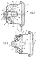
- the mode of realization of the invention here is a projector anti-fog. It has a rear housing 2, a sheet 4 fixed to the housing, an intermediate piece 6 fixed to the case, a front window 8 fixed to the part intermediate 6.
- the projector has a lamp holder 10 fixed to the housing and to the sheet metal, a lamp 12 and a connector 14 fixed to the lamp holder. It has a cradle 16 fixed to the housing and a reflector 18 fixed to the cradle.
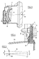
- the projector also has a screw adjustment 20 and an adjustment button 22 fixed to the screw as illustrated in particular in Figure 4.
- the housing 2 essentially comprises a bottom wall 24 generally planar and perpendicular to an axis horizontal 26 of the lamp and a side wall cylindrical 28 extending forward from the back wall.
- the side wall 28 has an edge before circular 30 inscribed in a plan perpendicular to the axis 26.
- the housing has shoulders 32 to some places at the junction between the bottom wall 24 and the side wall 28.
- the side wall 28 is flared at certain places 34, as illustrated in Figure 8.
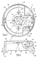
- the housing 2 has two straight bulges upper 36 and lower 38 located respectively in the first and fourth quadrants in front view. These bulges have a general shape of an isosceles triangle rectangle in front view on figure 7. They define protruding portions in the interior of the projector.
- the two bulges 36, 38 have two orifices facing each other, with a common axis 40 perpendicular to axis 26, not intersecting with it and vertical.
- the orifice 42 of the upper bulge 36 is open down, blind up but open in direction forward, while port 44 of lower bulge is crossing upward and the low but closed laterally.
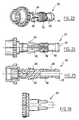
- the holes 42, 44 are suitable for receiving the screw adjustment 20 illustrated in Figures 23 to 25.
- This screw is engaged by its upper end 45 in the lower orifice 44, then up to the orifice upper 42.
- Elastic tabs 46 are connected by their front end to the body 48 of the screw and extend at rest away from the body of the screw rearward. Legs 46 flex when passing from port 44 then return to their original position after the screw has arrived in its position operation. The clipping tabs therefore prohibit removing the screw down.
- the screw is in abutment axial upwards against the bottom of the blind hole upper 42.
- the screw is guided in rotation around its axis in the two holes. Between them, the body of the screw has a threaded section 50 allowing activate the reflector as we will see below. This positioning of the screw guarantees the correct position angle of the net and therefore precise cooperation with the cradle.
- the screw has a keying lug 49 extending radially projecting from one side of the rod and requiring the screw to be mounted in the correct position on the housing otherwise the screw cannot be received on the housing because the tab abuts the housing.
- the rear wall 24 of the housing has a central opening 52 intended to be occupied by the lamp holder 10.
- the plate 4 has a general plane shape essentially in rhombus whose major axis is vertical.
- the plate is centered on the axis 26 of the lamp.
- the plate has two vertical edges rectilinear lateral 53 folded forward and perpendicular to the plane of the plate extending forward about 3 mm.
- Sheet 4 has a central opening 54 of substantially the same shape and same dimensions as that 52 of the rear wall of the housing and coming into coincidence therewith.
- Prison 4 is fixed to the rear wall 24 opposite the face before.
- the sheet is interposed axially between the wall rear 24 on the one hand, and the cradle 16 and the reflector 18 on the other hand.
- the sheet has stiffening ribs 56, here four in number, in relief of the front face of the sheet. These ribs are parallel to the respective inclined sides of the diamond.
- the sheet has two upper openings 58 and lower 60 intended to cooperate with fingers projecting from the rear wall 24 of the housing forward.
- the upper orifice 58 has a form of "H" lying. It is formed by a cut rectangular in which extend horizontally towards each other two tabs rectangular 62. These two tabs are slightly tilted forward, as shown in Figure 13.
- the finger 64 of the housing associated with this orifice has a profiled shape with square section in a plane perpendicular to axis 26. It is dimensioned so when the sheet 4 is pressed into position against the rear wall 24, the finger 64 enters the orifice 58 between the tabs 62, the lateral faces of the finger rubbing against the tabs or even bending them forward. However, given the inclination tabs forward, the friction forces of tabs on the finger against its recoil are much higher than those encountered during its advanced. The finger is therefore blocked in the orifice against its recoil.
- the cooperation between the lower orifice 60 and the associated finger 66 is based on the same principle.
- the finger 66 is of circular cross section.
- the orifice 60 has a cross shape and is defined by four triangular tabs 68 whose edges are look form the cross.
- the tip of the tabs is rounded and concave in order to conform to the curvature of the finger.
- the tabs 68 are still inclined towards the front as shown in Figure 11. Again, the tabs allow insertion of finger 66 into the opening towards the front but prohibit for essentially its withdrawal.
- the two pairs of fingers and holes ensure rigid fixing of the sheet 4 to the rear wall 24.
- the square section of the finger higher 64 is larger than that of the finger lower 66 so the upper finger 64 can only not be introduced into the lower opening 60 without force abnormally.
- the inclination of tabs forbidden to fix the sheet to the rear wall in a position such that the tabs would tilted backwards. We thus constitute means of coding that require mounting the sheet on the housing in the
- the orifice 52 of the case presents essentially three arc sections of circle 70 of the same radius, alternated with three sections in an arc 72 with the same larger radius than that of spokes 70. All sections are centered on axis 26.
- each pair has a large radius arc 72 followed by a small radius arc 70 with reference to the direction trigonometric 69.
- the housing has a relief 71 extending projecting from the front face of the wall rear, towards the front. This relief 71 presents a front helical ramp 73 of axis 26 moving away from the rear wall as you turn in direction 69.
- the rear wall also has a relief 74 extending at the edge of the orifice 52 between two reliefs 72.
- the sheet 4 has near its orifice 54 an edge folded back 76 coming into abutment against relief 74 at against the rotation of the plate 4 with respect to the rear wall in direction 69.
- the arcs of a circle 78, large radius, sheet metal, counterparts of those 72 of the rear wall, are longer than these so as not to hide the ramps 73 in front view.
- the lamp holder 10 comprises a body 80 having a general shape of revolution and three tabs 82 of which only one, upper, is illustrated, projecting radial from the periphery of the body.
- the body 80 comprises a double rear flange 84 fitted with a seal sealing and taking up play 86.
- the lamp holder 10 carries the lamp 86 and that the housing 2 carries the sheet 4.
- the lamp holder by the rear in the hole 52 of the rear wall and the plate up to put the seal 86 in axial stop front on the back side of the back wall, the flange 84 being itself in axial abutment against the back of the seal.
- the tabs 82 necessarily pass through the orifice look at large radius arcs because they extend radially too long to be able to penetrate opposite the arcs of a circle small radius.
- relief 74 one of the places where the tabs is smaller than the others.
- the tabs 82 have corresponding dimensions substantially to those of the passage locations, it it follows that the lamp holder cannot enter the orifice only in a single angular position around of the axis 26 relative to the housing. So we get here again a keying effect.
- the tabs are directly next to the ramps 73.
- the tongues 82 then follow the ramps 73 to finish pushing the lamp holder forward.
- the tabs are leaving finally the ramps to come into axial support on the sheet 4 at the arcs of a small radius.
- the lamp holder is rigidly fixed to the sheet 4 and to the housing 2 in a position very precisely defined thanks in particular to the rotational guidance of the body 80 of the lamp holder against the arcs of small circle Ray.
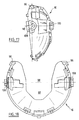
- the reflector has a generally concave shape and has an opening 89 in its center. Its internal reflective face 90 has different zones formed by paraboloids geometrically different and separated from each other others by recessed edges 91.
- the cradle 16 a a general shape close to that of the reflector, essentially shaped like a concave hemisphere. he also has a central hole 92 but this one is extended upwards by a notch 94 connecting the central hole 92 at the peripheral edge of the cradle of so this one has a general "U" shape in sight from the back or from the front.
- the "U” is essentially full, apart from the notch 94 and the orifice 92.
- the reflector 18 is rigidly fixed to the cradle 16 in coaxial position.
- the fixing means include two upper positioning hooks side 94 of the reflector, facing downwards and coming to rest on two contiguous reliefs 96 of the cradle at notch 94. They also include two tabs left and right positioning 95 of the reflector received backwards in two corresponding housing 98 of the cradle. The two legs 95 are different one of each other as well as housing 98 so the reflector can only be fixed in one position by relation to the cradle.
- the housing has two cylindrical housings 106 able to receive the reliefs 98 of the cradle which have a corresponding shape for guiding the cradle to rotation relative to the housing around an axis horizontal 108 perpendicular to that 26 of the lamp but extending under it.
- the cradle has two pins 120 extending backwards and able to come engaged by clipping with two reliefs 122 on the face internal side wall of the housing, so that the cradle pushed axially in the housing towards the rear is retained by clipping.
- the reliefs 122 have a curved shape with center of curvature directed towards the front, as shown in Figure 9, to allow the rotation of the cradle 16 relative to the housing 2 in despite this fixation.
- the two reliefs 98 are different from each other, as well as housing 106 for a polarizing effect that requires mounting the cradle on the housing in the single position provided, namely notch 94 upwards.
- the lugs 120 are guided by a groove 123 of the housing having one end flared forward.
- the cradle has on its rear side a threaded cavity 110 generally hollow cylindrical arranged so that this imprint comes engaged with thread 50 of adjusting screw 20 when the cradle is in position.
- adjusting screw around its axis, by example by means of button 22 which partly extends it lower, so the pivoting of the reflector 16 up or down around the axis 108.
- the threads of the screw 20 and the cradle 16 are arranged with sufficient clearance for the rotation of the cradle on a small angle does not interrupt catching nets.
- the footprint 110 of the cradle has a slightly convex profile in section vertical passing through the axis of the net.
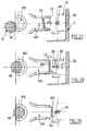
- the pins 120 When approaching the cradle on the housing, the pins 120 are guided in the grooves 123 before reception of the reliefs 98 in the housings 106 (figure 27). When the reliefs 98 arrive in the dwellings 106, the pins are still in the grooves (figure 28). At this time, the axis of the cradle is already positioned suitably compared to that of the housing. Moreover, the vertical clearance L2 between the lug and the groove is less than the vertical clearance between the threads 110 and 50. In addition, the horizontal distance L3 between the vertices of the net 100 and the top of the net 50 is less than the distance L4 remaining to be covered by the lug for out of the throat.
- Figure 5 illustrates the movement of the cradle 16 relative to the housing 2.
- the cradle can here be tilted from the horizontal by an angle a of 5.5 ° upwards and an angle b of 7.5 ° downwards to correct the angle of the headlight beam by reference to the actual attitude of the vehicle.
- the focus F of the reflector 18 is located on the pivot axis 108 vertically to the right of the axis 26 of the lamp and the housing.
- the vertical distance d separating them is very small, for example 0.7 mm.
- L denotes the center of the filament in FIG. 5.
- the lower generatrix of the horizontal cylindrical filament extending from front to back has its center substantially at the focus F.
- the button 22 presents upwardly oriented circular toothing its meshing with an elongated toothed member 130 such than a Phillips screwdriver for actuating the adjusting screw 20 and adjusting the trim by example manually or automatically from the dashboard.
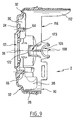
- the actuation by means of the screwdriver can be done horizontally, from the front or the side for example, or vertically from the bottom as shown in figure 4.
- the housing comprises a screen or visor 112 of cylindrical shape, axis 26, integral with the side wall 28 of the molded case.
- the upper and lower sides of the screen are in line with the external faces and internal side wall of the housing.
- the screen projects from the front edge 30 towards the front, direction of the ice 8.
- the screen 112 extends over a angular sector around the axis 26 less than 90 ° and here equal to 66 °.
- Intermediate piece 6 has a skirt cylindrical with axis 26 fixed by its rear edge to the exterior to the side wall 28 of the housing and carrying the glass by its front edge.
- screen 112 is interposed radially between the lamp 12, under the screen, and the intermediate part 6 on the screen.
- the screen extends forward further than the lamp.
- the screen protects the intermediate piece from air heated by the lamp and which rises in the enclosure inside of the projector.
- the sheet 4 will for example be made of galvanized steel.
- the glass 8 may be made of tempered glass.
- the intermediate part 6, the housing 2, the cradle 16, the adjusting screw 20 and the button 22 can be made of PBT (polybutylene terephthalate), plastic heat resistant.
- the lamp is for example a brand lamp Philips / Osram / GE type H 11.
- the reflector 18 is here made of steel alloy sheet aluminum.
- the seal 86 is made of silicone.
- the screen 112 is a room reported for example on the housing 2 or the part intermediate 6.
- the device could be a signaling light.
Landscapes
- Engineering & Computer Science (AREA)
- General Engineering & Computer Science (AREA)
- Non-Portable Lighting Devices Or Systems Thereof (AREA)
- Lighting Device Outwards From Vehicle And Optical Signal (AREA)
- Arrangements Of Lighting Devices For Vehicle Interiors, Mounting And Supporting Thereof, Circuits Therefore (AREA)
Abstract
Description
- la figure 1 est une vue en coupe suivant un plan axial vertical d'un projecteur selon l'invention ;
- la figure 2 est une vue en coupe du projecteur de la figure 1 suivant un plan axial horizontal ;
- la figure 3 est une vue en coupe du projecteur de la figure 1 suivant un plan vertical passant par la vis de réglage de l'inclinaison du réflecteur ;
- la figure 4 est une vue analogue à la figure 3 montrant l'actionnement de la vis de réglage ;
- la figure 5 est un schéma géométrique illustrant le débattement angulaire du réflecteur ;
- la figure 6 est une vue en coupe et en perspective simplifiée du projecteur de la figure 1 ;
- les figures 7 et 8 sont des vues de face et en coupe axiale suivant un plan horizontal du boítier du projecteur de la figure 1 ;
- la figure 9 est une vue en coupe axiale suivant un plan vertical du boítier de la figure 7 ;
- les figures 10, 11 et 12 sont des vues de face de dessous et de gauche de la tôle du projecteur de la figure 1 ;
- les figures 13 et 14 sont des vues locales de la tôle suivant les plans XIII-XIII et XIV-XIV de la figure 10 ;
- les figures 15 et 16 sont des vues arrière et de dessus du berceau du projecteur de la figure 1 ;
- les figures 17 et 18 sont des vues de gauche et de face du berceau de la figure 15 ;
- les figures 19 et 20 sont des vues de face et de gauche du réflecteur du projecteur de la figure 1 ;
- la figure 21 est une vue du réflecteur suivant la flèche XXI de la figure 19 ;
- la figure 22 est une vue du réflecteur suivant la flèche XXII de la figure 19 ;
- les figures 23, 24 et 25 sont des vues en perspective, de côté et en coupe axiale de la vis de réglage du projecteur de la figure 1 ;
- la figure 26 est une vue de côté du bouton de réglage associé à la vis ; et
- les figures 27, 28 et 29 montrent trois étapes de la cinématique d'assemblage du berceau sur le boítier.
Claims (15)
- Dispositif d'éclairage ou de signalisation pour véhicule comprenant un boítier (2) comportant une paroi arrière (24) en matière plastique et un porte-lampe (10) fixé à la paroi arrière (24), caractérisé en ce qu'il comporte en outre une plaque métallique (4) distincte du porte-lampe (10), s'étendant entre la paroi arrière (24) et un réflecteur (18), et fixée à la paroi arrière s'étendant d'un côté de la paroi arrière (24) dirigé vers la lampe (12), le porte-lampe (10) étant en appui sur la plaque métallique (4) suivant une direction axiale (26) de la lampe et comportant au moins un élément métallique (82) en contact avec la plaque métallique (4).
- Dispositif selon la revendication 1,
caractérisé en ce que la plaque métallique (4) présente au moins un pli. - Dispositif selon l'une quelconque des revendications 1 et 2, caractérisé en ce que la plaque métallique présente au moins une zone de bord (53) s'étendant à distance de toutes les autres pièces du dispositif.
- Dispositif selon l'une quelconque des revendications 1 à 3, caractérisé en ce qu'il comporte des moyens (76) de mise en butée de la plaque métallique (4) à l'encontre de sa rotation par rapport à la paroi arrière (24) dans au moins un sens (70).
- Dispositif selon l'une quelconque des revendications 1 à 4, caractérisé en ce que l'une parmi la paroi (24) et la plaque métallique (4) comporte au moins un relief (64, 66) et l'autre parmi la paroi et la plaque métallique présente au moins un orifice (58, 60) de retenue du relief.
- Dispositif selon la revendication 5,
caractérisé en ce qu'il comporte deux reliefs (64, 66) et deux orifices (58, 60), au moins l'un des reliefs étant apte à pénétrer dans un seul des orifices. - Dispositif selon la revendication 5 ou 6,
caractérisé en ce que le ou chaque orifice (58, 60) est défini par au moins une languette flexible (62, 68). - Dispositif selon l'une quelconque des revendications 1 à 7, caractérisé en ce qu'il comporte des moyens de fixation par baïonnettes (82) du porte-lampe (10) à la plaque (4).
- Dispositif selon la revendication 8,
caractérisé en ce qu'il est agencé de sorte que les baïonnettes (82) viennent en appui sur la plaque métallique (4) suivant une direction axiale (26) de la lampe. - Dispositif selon la revendication 8 ou 9, caractérisé en ce qu'il présente des rampes (73) aptes à être parcourues par les baïonnettes (82) lors d'une rotation du porte-lampe (10) pour amener les baïonnettes en appui sur la plaque métallique (4).
- Dispositif selon l'une quelconque des revendications 1 à 10, caractérisé en ce qu'il comporte un boítier (2), une glace (8), une pièce intermédiaire (6) reliant la glace au boítier et un écran (112) s'étendant en avant d'une zone supérieure du boítier en direction de la glace.
- Dispositif selon l'une quelconque des revendications 1 à 11, caractérisé en ce que le réflecteur (18) est monté mobile par rapport au boítier, la lampe étant rigidement fixée au boítier.
- Dispositif selon l'une quelconque des revendications 1 à 12, caractérisé en ce qu'il comporte un boítier (2) comprenant la paroi arrière, un réflecteur (18) et un berceau (16) reliant le réflecteur au boítier et présentant une ouverture (94) en partie supérieure.
- Dispositif selon l'une quelconque des revendications 1 à 13, caractérisé en ce qu'il s'agit d'un projecteur.
- Dispositif selon l'une quelconque des revendications 1 à 14, caractérisé en ce qu'il s'agit d'un projecteur antibrouillard.
Applications Claiming Priority (2)
| Application Number | Priority Date | Filing Date | Title |
|---|---|---|---|
| FR0005489A FR2808316B1 (fr) | 2000-04-28 | 2000-04-28 | Dispositif d'eclairage ou de signalisation pour vehicule a boitier renforce |
| FR0005489 | 2000-04-28 |
Publications (2)
| Publication Number | Publication Date |
|---|---|
| EP1150065A1 true EP1150065A1 (fr) | 2001-10-31 |
| EP1150065B1 EP1150065B1 (fr) | 2007-08-01 |
Family
ID=8849730
Family Applications (1)
| Application Number | Title | Priority Date | Filing Date |
|---|---|---|---|
| EP01400903A Expired - Lifetime EP1150065B1 (fr) | 2000-04-28 | 2001-04-09 | Dispositif d'éclairage ou de signalisation pour véhicule à boitier renforcé |
Country Status (6)
| Country | Link |
|---|---|
| US (1) | US6513960B2 (fr) |
| EP (1) | EP1150065B1 (fr) |
| AT (1) | ATE368825T1 (fr) |
| DE (1) | DE60129628T2 (fr) |
| ES (1) | ES2290101T3 (fr) |
| FR (1) | FR2808316B1 (fr) |
Cited By (1)
| Publication number | Priority date | Publication date | Assignee | Title |
|---|---|---|---|---|
| EP1867918B1 (fr) * | 2006-06-15 | 2011-01-05 | Valeo Vision | Projecteur comportant un élément de support rapporté fixe sur lequel un réflecteur est monté pivotant |
Families Citing this family (11)
| Publication number | Priority date | Publication date | Assignee | Title |
|---|---|---|---|---|
| JP4043818B2 (ja) * | 2002-03-22 | 2008-02-06 | 株式会社小糸製作所 | 車輌用前照灯 |
| TW200916690A (en) * | 2007-10-12 | 2009-04-16 | Dosun Solar Technology Co Ltd | LED (light emitting diode) lamps |
| JP5393889B2 (ja) * | 2010-07-05 | 2014-01-22 | 三菱電機株式会社 | ヘッドランプ用led光源点灯装置 |
| JP5898937B2 (ja) * | 2011-12-05 | 2016-04-06 | 株式会社小糸製作所 | 車輌用前照灯 |
| DE202012005795U1 (de) | 2012-06-14 | 2012-07-09 | Automotive Lighting Reutlingen Gmbh | Beleuchtungseinrichtung eines Kraftfahrzeugs |
| JP2014157710A (ja) * | 2013-02-15 | 2014-08-28 | Koito Mfg Co Ltd | 車両用照明装置 |
| US20150163860A1 (en) * | 2013-12-06 | 2015-06-11 | Lam Research Corporation | Apparatus and method for uniform irradiation using secondary irradiant energy from a single light source |
| SI25444A (sl) * | 2017-06-07 | 2018-12-31 | Hella Saturnus Slovenija d.o.o. | Sklop za nastavljanje položaja svetlobnega telesa |
| CN110220153B (zh) * | 2018-03-02 | 2023-01-06 | 法雷奥照明湖北技术中心有限公司 | 用于发光模块的调节装置、发光模块和车辆 |
| DE102019003866A1 (de) * | 2019-05-31 | 2020-12-03 | Daimler Ag | Leuchtvorrichtung für ein Kraftfahrzeug |
| US11725792B2 (en) * | 2020-12-29 | 2023-08-15 | Wen Chen | Headlight socket |
Citations (8)
| Publication number | Priority date | Publication date | Assignee | Title |
|---|---|---|---|---|
| GB2022234A (en) * | 1978-06-06 | 1979-12-12 | Bosch Gmbh Robert | Vehicle lamp |
| GB2070755A (en) * | 1980-02-29 | 1981-09-09 | Marchal Equip Auto | Lamp in particular for motor vehicles |
| US4563730A (en) * | 1981-12-24 | 1986-01-07 | Ichikoh Industries, Ltd. | Vehicle head lamp with synthetic resin reflector and ring-shaped heat shielding member |
| DE3620800A1 (de) * | 1986-06-20 | 1987-12-23 | Bosch Gmbh Robert | Befestigungsanordnung fuer reflektoren von kraftfahrzeug-scheinwerfern |
| US4926301A (en) * | 1986-11-13 | 1990-05-15 | General Motors Corporation | Headlamp assembly |
| US5491619A (en) * | 1995-03-20 | 1996-02-13 | Caterpillar Inc. | Vibration and shock isolated headlight mounting system |
| US5510968A (en) * | 1995-08-28 | 1996-04-23 | Chrysler Corporation | Back light assembly |
| US5702173A (en) * | 1994-03-09 | 1997-12-30 | Koito Manufacturing Co., Ltd. | Vehicular lamp having simplified structure and reduced condensation |
Family Cites Families (2)
| Publication number | Priority date | Publication date | Assignee | Title |
|---|---|---|---|---|
| US4709305A (en) * | 1986-10-03 | 1987-11-24 | General Motors Corporation | Electrical connector for headlight assembly |
| US5113320A (en) * | 1990-08-16 | 1992-05-12 | Robart Enterprises, Inc. | Spherically adjustable headlamp mounting system |
-
2000
- 2000-04-28 FR FR0005489A patent/FR2808316B1/fr not_active Expired - Lifetime
-
2001
- 2001-04-09 AT AT01400903T patent/ATE368825T1/de active
- 2001-04-09 DE DE60129628T patent/DE60129628T2/de not_active Expired - Lifetime
- 2001-04-09 ES ES01400903T patent/ES2290101T3/es not_active Expired - Lifetime
- 2001-04-09 EP EP01400903A patent/EP1150065B1/fr not_active Expired - Lifetime
- 2001-04-25 US US09/842,325 patent/US6513960B2/en not_active Expired - Lifetime
Patent Citations (8)
| Publication number | Priority date | Publication date | Assignee | Title |
|---|---|---|---|---|
| GB2022234A (en) * | 1978-06-06 | 1979-12-12 | Bosch Gmbh Robert | Vehicle lamp |
| GB2070755A (en) * | 1980-02-29 | 1981-09-09 | Marchal Equip Auto | Lamp in particular for motor vehicles |
| US4563730A (en) * | 1981-12-24 | 1986-01-07 | Ichikoh Industries, Ltd. | Vehicle head lamp with synthetic resin reflector and ring-shaped heat shielding member |
| DE3620800A1 (de) * | 1986-06-20 | 1987-12-23 | Bosch Gmbh Robert | Befestigungsanordnung fuer reflektoren von kraftfahrzeug-scheinwerfern |
| US4926301A (en) * | 1986-11-13 | 1990-05-15 | General Motors Corporation | Headlamp assembly |
| US5702173A (en) * | 1994-03-09 | 1997-12-30 | Koito Manufacturing Co., Ltd. | Vehicular lamp having simplified structure and reduced condensation |
| US5491619A (en) * | 1995-03-20 | 1996-02-13 | Caterpillar Inc. | Vibration and shock isolated headlight mounting system |
| US5510968A (en) * | 1995-08-28 | 1996-04-23 | Chrysler Corporation | Back light assembly |
Cited By (1)
| Publication number | Priority date | Publication date | Assignee | Title |
|---|---|---|---|---|
| EP1867918B1 (fr) * | 2006-06-15 | 2011-01-05 | Valeo Vision | Projecteur comportant un élément de support rapporté fixe sur lequel un réflecteur est monté pivotant |
Also Published As
| Publication number | Publication date |
|---|---|
| US6513960B2 (en) | 2003-02-04 |
| FR2808316A1 (fr) | 2001-11-02 |
| DE60129628D1 (de) | 2007-09-13 |
| EP1150065B1 (fr) | 2007-08-01 |
| FR2808316B1 (fr) | 2002-07-12 |
| ES2290101T3 (es) | 2008-02-16 |
| ATE368825T1 (de) | 2007-08-15 |
| US20020006043A1 (en) | 2002-01-17 |
| DE60129628T2 (de) | 2008-05-21 |
Similar Documents
| Publication | Publication Date | Title |
|---|---|---|
| EP1150065B1 (fr) | Dispositif d'éclairage ou de signalisation pour véhicule à boitier renforcé | |
| EP0847894B1 (fr) | Projecteur de véhicule automobile équipé de moyens de réglage de réflecteur perfectionnés | |
| EP1150064B1 (fr) | Dispositif d'éclairage ou de signalisation pour véhicule de haute tenue thermique | |
| EP1873445A2 (fr) | Projecteur muni d'un réflecteur pivotant comportant un écrou de réglage de la position angulaire du réflecteur | |
| FR2774050A1 (fr) | Essuie-glace de vehicule automobile | |
| FR2790308A1 (fr) | Projecteur a occulteur aere pour vehicule automobile | |
| EP1150062A1 (fr) | Dispositif d'éclairage ou de signalisation pour véhicule à écran thermique | |
| EP0588715B1 (fr) | Projecteur comportant un dispositif correcteur et des moyens de réglage du zéro du dispositif correcteur | |
| EP0517598B1 (fr) | Dispositif de fixation d'un organe d'éclairage ou de signalisation de véhicule automobile avec compensation de tolérances | |
| EP0624492B1 (fr) | Dispositif de montage de deux dispositifs d'éclairage ou de signalisation de véhicule automobile | |
| EP0984222B1 (fr) | Projecteur de véhicule automobile à lampe transversale équipé de moyens perfectionnés de la lampe | |
| EP0588725B1 (fr) | Projecteur comprenant un module correcteur à sortie rotative | |
| EP1160128B1 (fr) | Dispositif d'éclairage ou de signalisation pour véhicule comportant deux pièces fixées par clipsage | |
| EP1867918B1 (fr) | Projecteur comportant un élément de support rapporté fixe sur lequel un réflecteur est monté pivotant | |
| FR2697900A1 (fr) | Système de réglage d'inclinaison du faisceau lumineux d'un projecteur pour véhicule automobile. | |
| FR2711217A1 (fr) | Feu de signalisation à optique réglable notamment pour lunette arrière de véhicule automobile. | |
| FR2761313A1 (fr) | Console de pavillon de vehicule automobile adaptee pour etre montee sur la garniture de pavillon de vehicule et procede de montage de la console sur la garniture | |
| FR2709810A1 (fr) | Projecteur d'aspect intérieur amélioré pour véhicule automobile. | |
| FR2650373A1 (fr) | Couvercle pour plaque de cuisson integrable dans des dessus de meubles de cuisine | |
| EP0870643B1 (fr) | Dispositif d'éclairage ou de signalisation à glace affleurante et moyens de calage, pour véhicule automobile | |
| EP2169297A1 (fr) | Module optique comportant un élément de déviation optique | |
| FR2715458A1 (fr) | Dispositif d'éclairage ou de signalisation à moyens perfectionnés de montage de lampe, pour véhicule automobile. | |
| EP0972675B1 (fr) | Elément de fixation intermédiaire pour le montage d'un élément sur une partie d'appui d'un projecteur de véhicule automobile | |
| FR2757117A1 (fr) | Projecteur de vehicule automobile equipe de moyens de reglage de reflecteur perfectionnes | |
| EP0933254A1 (fr) | Elément de fixation intermédiaire pour le montage d'un réflecteur sur une partie d'appui d'un projecteur |
Legal Events
| Date | Code | Title | Description |
|---|---|---|---|
| PUAI | Public reference made under article 153(3) epc to a published international application that has entered the european phase |
Free format text: ORIGINAL CODE: 0009012 |
|
| AK | Designated contracting states |
Kind code of ref document: A1 Designated state(s): AT BE CH CY DE DK ES FI FR GB GR IE IT LI LU MC NL PT SE TR Kind code of ref document: A1 Designated state(s): AT DE ES GB IT |
|
| AX | Request for extension of the european patent |
Free format text: AL;LT;LV;MK;RO;SI |
|
| 17P | Request for examination filed |
Effective date: 20020404 |
|
| AKX | Designation fees paid |
Free format text: AT DE ES GB IT |
|
| GRAP | Despatch of communication of intention to grant a patent |
Free format text: ORIGINAL CODE: EPIDOSNIGR1 |
|
| GRAS | Grant fee paid |
Free format text: ORIGINAL CODE: EPIDOSNIGR3 |
|
| GRAA | (expected) grant |
Free format text: ORIGINAL CODE: 0009210 |
|
| AK | Designated contracting states |
Kind code of ref document: B1 Designated state(s): AT DE ES GB IT |
|
| REG | Reference to a national code |
Ref country code: GB Ref legal event code: FG4D Free format text: NOT ENGLISH |
|
| REF | Corresponds to: |
Ref document number: 60129628 Country of ref document: DE Date of ref document: 20070913 Kind code of ref document: P |
|
| REG | Reference to a national code |
Ref country code: ES Ref legal event code: FG2A Ref document number: 2290101 Country of ref document: ES Kind code of ref document: T3 |
|
| GBV | Gb: ep patent (uk) treated as always having been void in accordance with gb section 77(7)/1977 [no translation filed] |
Effective date: 20070801 |
|
| PLBI | Opposition filed |
Free format text: ORIGINAL CODE: 0009260 |
|
| PG25 | Lapsed in a contracting state [announced via postgrant information from national office to epo] |
Ref country code: GB Free format text: LAPSE BECAUSE OF FAILURE TO SUBMIT A TRANSLATION OF THE DESCRIPTION OR TO PAY THE FEE WITHIN THE PRESCRIBED TIME-LIMIT Effective date: 20070801 |
|
| PLAX | Notice of opposition and request to file observation + time limit sent |
Free format text: ORIGINAL CODE: EPIDOSNOBS2 |
|
| 26 | Opposition filed |
Opponent name: AUTOMOTIVE LIGHTING REUTLINGEN GMBH Effective date: 20080430 |
|
| PLAF | Information modified related to communication of a notice of opposition and request to file observations + time limit |
Free format text: ORIGINAL CODE: EPIDOSCOBS2 |
|
| PLBB | Reply of patent proprietor to notice(s) of opposition received |
Free format text: ORIGINAL CODE: EPIDOSNOBS3 |
|
| PLCK | Communication despatched that opposition was rejected |
Free format text: ORIGINAL CODE: EPIDOSNREJ1 |
|
| APBM | Appeal reference recorded |
Free format text: ORIGINAL CODE: EPIDOSNREFNO |
|
| APBP | Date of receipt of notice of appeal recorded |
Free format text: ORIGINAL CODE: EPIDOSNNOA2O |
|
| APAH | Appeal reference modified |
Free format text: ORIGINAL CODE: EPIDOSCREFNO |
|
| APBQ | Date of receipt of statement of grounds of appeal recorded |
Free format text: ORIGINAL CODE: EPIDOSNNOA3O |
|
| APBU | Appeal procedure closed |
Free format text: ORIGINAL CODE: EPIDOSNNOA9O |
|
| PLBN | Opposition rejected |
Free format text: ORIGINAL CODE: 0009273 |
|
| STAA | Information on the status of an ep patent application or granted ep patent |
Free format text: STATUS: OPPOSITION REJECTED |
|
| 27O | Opposition rejected |
Effective date: 20120426 |
|
| REG | Reference to a national code |
Ref country code: DE Ref legal event code: R100 Ref document number: 60129628 Country of ref document: DE Effective date: 20120426 |
|
| PGFP | Annual fee paid to national office [announced via postgrant information from national office to epo] |
Ref country code: DE Payment date: 20170412 Year of fee payment: 17 |
|
| PGFP | Annual fee paid to national office [announced via postgrant information from national office to epo] |
Ref country code: IT Payment date: 20170411 Year of fee payment: 17 Ref country code: ES Payment date: 20170508 Year of fee payment: 17 |
|
| REG | Reference to a national code |
Ref country code: DE Ref legal event code: R082 Ref document number: 60129628 Country of ref document: DE |
|
| REG | Reference to a national code |
Ref country code: DE Ref legal event code: R079 Ref document number: 60129628 Country of ref document: DE Free format text: PREVIOUS MAIN CLASS: F21S0008100000 Ipc: F21S0043000000 |
|
| PGFP | Annual fee paid to national office [announced via postgrant information from national office to epo] |
Ref country code: AT Payment date: 20180322 Year of fee payment: 18 |
|
| REG | Reference to a national code |
Ref country code: DE Ref legal event code: R119 Ref document number: 60129628 Country of ref document: DE |
|
| PG25 | Lapsed in a contracting state [announced via postgrant information from national office to epo] |
Ref country code: DE Free format text: LAPSE BECAUSE OF NON-PAYMENT OF DUE FEES Effective date: 20181101 |
|
| PG25 | Lapsed in a contracting state [announced via postgrant information from national office to epo] |
Ref country code: IT Free format text: LAPSE BECAUSE OF NON-PAYMENT OF DUE FEES Effective date: 20180409 |
|
| REG | Reference to a national code |
Ref country code: ES Ref legal event code: FD2A Effective date: 20190911 |
|
| PG25 | Lapsed in a contracting state [announced via postgrant information from national office to epo] |
Ref country code: ES Free format text: LAPSE BECAUSE OF NON-PAYMENT OF DUE FEES Effective date: 20180410 |
|
| REG | Reference to a national code |
Ref country code: AT Ref legal event code: MM01 Ref document number: 368825 Country of ref document: AT Kind code of ref document: T Effective date: 20190409 |
|
| PG25 | Lapsed in a contracting state [announced via postgrant information from national office to epo] |
Ref country code: AT Free format text: LAPSE BECAUSE OF NON-PAYMENT OF DUE FEES Effective date: 20190409 |