EP1150124A2 - Capteur de rotation dans un chariot élévateur et roue pour un chariot élévateur - Google Patents
Capteur de rotation dans un chariot élévateur et roue pour un chariot élévateur Download PDFInfo
- Publication number
- EP1150124A2 EP1150124A2 EP01109935A EP01109935A EP1150124A2 EP 1150124 A2 EP1150124 A2 EP 1150124A2 EP 01109935 A EP01109935 A EP 01109935A EP 01109935 A EP01109935 A EP 01109935A EP 1150124 A2 EP1150124 A2 EP 1150124A2
- Authority
- EP
- European Patent Office
- Prior art keywords
- sensor
- reach
- wheel
- rotation detector
- detector according
- Prior art date
- Legal status (The legal status is an assumption and is not a legal conclusion. Google has not performed a legal analysis and makes no representation as to the accuracy of the status listed.)
- Withdrawn
Links
- 239000002184 metal Substances 0.000 claims description 17
- 229910052751 metal Inorganic materials 0.000 claims description 17
- 239000000463 material Substances 0.000 claims description 5
- 238000005520 cutting process Methods 0.000 claims description 2
- 239000000696 magnetic material Substances 0.000 claims description 2
- 238000001514 detection method Methods 0.000 description 14
- 230000006641 stabilisation Effects 0.000 description 7
- 238000011105 stabilization Methods 0.000 description 7
- 230000008901 benefit Effects 0.000 description 5
- 238000006073 displacement reaction Methods 0.000 description 5
- 239000004020 conductor Substances 0.000 description 4
- 230000001133 acceleration Effects 0.000 description 3
- 238000000034 method Methods 0.000 description 3
- XEEYBQQBJWHFJM-UHFFFAOYSA-N Iron Chemical compound [Fe] XEEYBQQBJWHFJM-UHFFFAOYSA-N 0.000 description 2
- 230000009471 action Effects 0.000 description 2
- 238000006243 chemical reaction Methods 0.000 description 2
- 230000002452 interceptive effect Effects 0.000 description 2
- 230000007774 longterm Effects 0.000 description 2
- 230000007246 mechanism Effects 0.000 description 2
- 230000002093 peripheral effect Effects 0.000 description 2
- 230000009467 reduction Effects 0.000 description 2
- 239000000725 suspension Substances 0.000 description 2
- JOYRKODLDBILNP-UHFFFAOYSA-N Ethyl urethane Chemical compound CCOC(N)=O JOYRKODLDBILNP-UHFFFAOYSA-N 0.000 description 1
- 230000002411 adverse Effects 0.000 description 1
- 238000005452 bending Methods 0.000 description 1
- 238000005266 casting Methods 0.000 description 1
- 230000008859 change Effects 0.000 description 1
- 239000012530 fluid Substances 0.000 description 1
- 238000005242 forging Methods 0.000 description 1
- 239000010720 hydraulic oil Substances 0.000 description 1
- 229910052742 iron Inorganic materials 0.000 description 1
- 230000005389 magnetism Effects 0.000 description 1
- 238000004519 manufacturing process Methods 0.000 description 1
- 238000005259 measurement Methods 0.000 description 1
- 239000003921 oil Substances 0.000 description 1
- 230000002040 relaxant effect Effects 0.000 description 1
- 230000003252 repetitive effect Effects 0.000 description 1
- 239000011347 resin Substances 0.000 description 1
- 229920005989 resin Polymers 0.000 description 1
- 238000005096 rolling process Methods 0.000 description 1
- 239000002023 wood Substances 0.000 description 1
Images





Classifications
-
- B—PERFORMING OPERATIONS; TRANSPORTING
- B66—HOISTING; LIFTING; HAULING
- B66F—HOISTING, LIFTING, HAULING OR PUSHING, NOT OTHERWISE PROVIDED FOR, e.g. DEVICES WHICH APPLY A LIFTING OR PUSHING FORCE DIRECTLY TO THE SURFACE OF A LOAD
- B66F9/00—Devices for lifting or lowering bulky or heavy goods for loading or unloading purposes
- B66F9/06—Devices for lifting or lowering bulky or heavy goods for loading or unloading purposes movable, with their loads, on wheels or the like, e.g. fork-lift trucks
- B66F9/075—Constructional features or details
- B66F9/08—Masts; Guides; Chains
- B66F9/10—Masts; Guides; Chains movable in a horizontal direction relative to truck
-
- B—PERFORMING OPERATIONS; TRANSPORTING
- B66—HOISTING; LIFTING; HAULING
- B66F—HOISTING, LIFTING, HAULING OR PUSHING, NOT OTHERWISE PROVIDED FOR, e.g. DEVICES WHICH APPLY A LIFTING OR PUSHING FORCE DIRECTLY TO THE SURFACE OF A LOAD
- B66F9/00—Devices for lifting or lowering bulky or heavy goods for loading or unloading purposes
- B66F9/06—Devices for lifting or lowering bulky or heavy goods for loading or unloading purposes movable, with their loads, on wheels or the like, e.g. fork-lift trucks
- B66F9/075—Constructional features or details
- B66F9/0755—Position control; Position detectors
-
- G—PHYSICS
- G01—MEASURING; TESTING
- G01P—MEASURING LINEAR OR ANGULAR SPEED, ACCELERATION, DECELERATION, OR SHOCK; INDICATING PRESENCE, ABSENCE, OR DIRECTION, OF MOVEMENT
- G01P1/00—Details of instruments
- G01P1/02—Housings
- G01P1/026—Housings for speed measuring devices, e.g. pulse generator
Definitions
- a reach forklift truck has a pair of reach legs, which extend forward from a vehicle body. Each of the reach legs includes a reach rail.
- a mast assembly which functions as a cargo carrying apparatus, is movable forward and backward along a pair of reach rails.
- Reach forklift trucks include a tricycle type forklift truck which includes one rear wheel and two front wheels. The rear wheel is used for driving and steering the wheels.
- a forklift truck additionally includes an auxiliary wheel (caster wheel) adjacent to a rear wheel, regardless of whether it is a tricycle type forklift truck.
- Each of the front wheels is supported by an axle secured to a side wall of an associated reach rail.
- a reach forklift truck detects the rotation of a drive motor for driving a drive wheel to detect the vehicle speed.
- detection of rotating of front wheels is desirable in some cases.
- Japanese Unexamined Patent Publication No. Hei 6-191250 discloses a reach forklift truck, which is equipped with a sensor for detecting rotation of front wheels.
- the reach forklift truck 91 of this publication is a three-wheel drive vehicle in which a pair of front wheels 92 is powered. Each of the front wheels 92 is supported by one of a pair of reach rails 95. The driving force of a motor 96 is transmitted to the front wheels 92 through a gear box 97.
- a sensor 94 is located in the gear box 97 for detecting rotation of gears in the gear box 97.
- a sensor for detecting rotation of the wheels is mainly used to (a) detect the vehicle speed, and (b) control the speed of the motor for driving the drive wheels.
- the sensor detects the rotational speed of a rotor, such as a gear for transmitting the driving torque, or the rotational speed of the motor to indirectly detect the rotational speed of the drive wheels.
- the rotational speed of the drive wheels is detected, but the rotational speed of a follower wheel is not detected for any of the purposes (a), (b).
- a sensor must be located near a front wheel for detecting the rotation of the front wheel.
- the positioning of a sensor near a front wheel is inappropriate due to the following problems.
- the width of the forklift truck is increased.
- the width of the forklift truck is slightly less than the width of a pallet. Further increasing the width due to the addition of the sensor would lead to difficulties in removing a pallet that is sandwiched between and placed behind two pallets and difficulties in passing through a space as narrow as a pallet. This would significantly reduce the efficiency of cargo transportation.
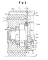
- the sensor 30 is positioned substantially within the lateral dimensions of the reach rail 21. This positioning prevents a foreign object such as a rope wound around the axle 31 between the front wheel 11 and the reach rail 21 from reaching the sensor 30.
- the outer surface of the sensor portion 30a protrudes slightly outward from the outer surface of the reach rail 21 in such a degree that a foreign object is not wound (e.g. 1 to 2 mm).
- the guard 40 also protrudes slightly outward from the outer surface of the reach rail 21 such that the sensor 30 can be fully protected thereby over the entire vehicle width direction.
- the sensor 30 and the front wheel 11 are spaced apart by such a distance that allows a foreign object wound around the axle 31 to pass.
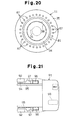
- the control unit 29 opens the electromagnetic valve of the brake valve unit (not shown) to actuate the brake device 38. Subsequently, the front wheels 11 are braked for restraint such that the braking distance of the forklift truck 10 is not too long. Detected values of the right and left sensors 30 are also used for the turn stabilization control. Specifically, the control unit 29 measures the difference in rotational speed between the right and left front wheels 11 and the vehicle speed based on the numbers of input pulses from the right and left sensors 30 per unit time and estimates lateral acceleration, which acts in the right and left directions of the vehicle body 14, based on these measured values. Then, if the estimated lateral acceleration exceeds a threshold value, the control unit 29 closes the electromagnetic valve (not shown) and locks a lock cylinder (hydraulic cylinder) to lock a suspension mechanism, thereby restricting rolling of the vehicle body 14.
- a lock cylinder hydroaulic cylinder
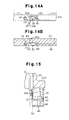
- a foreign object such as a rope wound around the axle 31 is cut by the cutter 48, thereby avoiding problems resulting from the foreign object.
- a high detection accuracy of the sensor 30 can be maintained for a long term.
- the inclined portions 40a, 40b are inclined with respect to the floor surface R, it is possible to distribute an impact force applied by an obstacle on the floor surface R to the guard 40 when the former collides with the latter. As a result, the guard 40 is less susceptible to deformation, and the position of the sensor 30 is hardly shifted even if the guard 40 functions simultaneously as a bracket. Thus, a high detection accuracy of the sensor 30 is maintained.
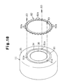
- metal pins 87 may be implanted into the inner side of the tire 35 at a constant pitch in the circumferential direction so that heads of the respective pins 87 are used as the detectable portion.
- the sensor 30 may be provided only on one of the right and left front wheels 11. With the single sensor 30, a detected rotational speed of the front wheel 11 would be affected by a direction in which the vehicle turns (a different detected value is indicated depending on whether the sensor is attached to the inner wheel or to the outer wheel). However, if a steering angle (tire angle) of the drive wheel 12 is detected, for example, by a tire angle sensor and corrected, a converted follower wheel vehicle speed can be correctly calculated even only from the rotational speed of the front wheel 11 detected at the preceding time. It is therefore possible to correctly detect slippage of the drive wheel 12.
- the restricting surfaces for restricting right and left swing of the forks 24 are not limited to the inner walls 21b of the reach rails 21.
- another auxiliary element is fixed to the inside of each reach rail, with the inner side of the auxiliary element used as the restricting surface, and the sensor 30 is positioned such that it does not protrude from the inner side of the auxiliary element.
- the restricting surfaces may be formed of any members as long as they can restrict the forks 24 swinging to the right and left to prevent it from interfering with the sensor 30.
- the restricting surfaces may be implemented by the inner sides of the guard which protrude to the inside of the reach rail 21 for protecting the sensor 30. When the guard does not function as a bracket for the sensor 30, the sensor 30 is held at the correct position even if the fork 24 strikes against the guard to result in a shift in position of the guard.
Landscapes
- Engineering & Computer Science (AREA)
- Transportation (AREA)
- Structural Engineering (AREA)
- Civil Engineering (AREA)
- Life Sciences & Earth Sciences (AREA)
- Geology (AREA)
- Mechanical Engineering (AREA)
- Physics & Mathematics (AREA)
- General Physics & Mathematics (AREA)
- Forklifts And Lifting Vehicles (AREA)
- Regulating Braking Force (AREA)
- Transmission And Conversion Of Sensor Element Output (AREA)
Applications Claiming Priority (2)
| Application Number | Priority Date | Filing Date | Title |
|---|---|---|---|
| JP2000124333A JP3785897B2 (ja) | 2000-04-25 | 2000-04-25 | リーチ式荷役車両における前輪回転検出装置 |
| JP2000124333 | 2000-04-25 |
Publications (2)
| Publication Number | Publication Date |
|---|---|
| EP1150124A2 true EP1150124A2 (fr) | 2001-10-31 |
| EP1150124A3 EP1150124A3 (fr) | 2003-10-22 |
Family
ID=18634477
Family Applications (1)
| Application Number | Title | Priority Date | Filing Date |
|---|---|---|---|
| EP01109935A Withdrawn EP1150124A3 (fr) | 2000-04-25 | 2001-04-24 | Capteur de rotation dans un chariot élévateur et roue pour un chariot élévateur |
Country Status (3)
| Country | Link |
|---|---|
| EP (1) | EP1150124A3 (fr) |
| JP (1) | JP3785897B2 (fr) |
| TW (1) | TWM280480U (fr) |
Cited By (8)
| Publication number | Priority date | Publication date | Assignee | Title |
|---|---|---|---|---|
| GB2385044A (en) * | 2002-02-12 | 2003-08-13 | Nippon Yusoki Co Ltd | Reach type fork lift truck with rotation sensor |
| EP1477453A1 (fr) * | 2003-05-14 | 2004-11-17 | Jungheinrich Aktiengesellschaft | Chariot élévateur à fourches à mât déplaçable |
| EP2762439A1 (fr) * | 2013-02-04 | 2014-08-06 | KION Warehouse Systems GmbH | Chariot de manutention doté d'un capteur de position |
| CN107449931A (zh) * | 2017-09-05 | 2017-12-08 | 中铁工程装备集团机电工程有限公司 | 隧道机车的轮轴测速码盘装置 |
| CN107585143A (zh) * | 2017-09-06 | 2018-01-16 | 安徽合力股份有限公司 | 具有制动鼓与轮辋集成的支撑轮的前移式叉车底盘总成 |
| CN112958980A (zh) * | 2021-03-04 | 2021-06-15 | 庆铃汽车(集团)有限公司 | 用于自动化焊接的车身侧围和底板夹具总成 |
| CN116425085A (zh) * | 2023-06-14 | 2023-07-14 | 河南垣发专用车辆集团有限公司 | 一种具有安全保护功能的叉装车 |
| EP4657078A1 (fr) | 2024-05-30 | 2025-12-03 | Stäubli WFT GmbH | Agencement de capteur de vitesse et chariot élévateur à fourche comprenant un tel agencement |
Families Citing this family (2)
| Publication number | Priority date | Publication date | Assignee | Title |
|---|---|---|---|---|
| JP5472938B2 (ja) * | 2011-08-25 | 2014-04-16 | ニチユ三菱フォークリフト株式会社 | リーチ型フォークリフト |
| JP2017147883A (ja) * | 2016-02-18 | 2017-08-24 | ニチユ三菱フォークリフト株式会社 | 産業車両及びその制御方法 |
Citations (3)
| Publication number | Priority date | Publication date | Assignee | Title |
|---|---|---|---|---|
| JPH06191251A (ja) | 1992-12-26 | 1994-07-12 | Toyota Autom Loom Works Ltd | リーチ式フォークリフトのサスペンション装置 |
| JPH06191250A (ja) | 1992-12-25 | 1994-07-12 | Toyota Autom Loom Works Ltd | リーチ式フォークリフトのサスペンション装置 |
| JPH10297900A (ja) | 1997-04-22 | 1998-11-10 | Nippon Yusoki Co Ltd | リーチ型フォークリフトの姿勢安定装置 |
Family Cites Families (5)
| Publication number | Priority date | Publication date | Assignee | Title |
|---|---|---|---|---|
| US3616953A (en) * | 1969-04-14 | 1971-11-02 | Towmotor Corp | Narrow-aisle truck with retractable arms |
| US4011478A (en) * | 1975-06-02 | 1977-03-08 | Texas Instruments Incorporated | Magnetic speed sensing mechanism |
| JP3396279B2 (ja) * | 1993-11-05 | 2003-04-14 | 白光機器株式会社 | フォークリフト用スピード警報装置 |
| JPH08194535A (ja) * | 1995-01-18 | 1996-07-30 | Hitachi Cable Ltd | 位置検出システム |
| JPH1141716A (ja) * | 1997-07-22 | 1999-02-12 | Shinko Electric Co Ltd | リーチフォークリフト |
-
2000
- 2000-04-25 JP JP2000124333A patent/JP3785897B2/ja not_active Expired - Lifetime
-
2001
- 2001-04-19 TW TW94202620U patent/TWM280480U/zh not_active IP Right Cessation
- 2001-04-24 EP EP01109935A patent/EP1150124A3/fr not_active Withdrawn
Patent Citations (3)
| Publication number | Priority date | Publication date | Assignee | Title |
|---|---|---|---|---|
| JPH06191250A (ja) | 1992-12-25 | 1994-07-12 | Toyota Autom Loom Works Ltd | リーチ式フォークリフトのサスペンション装置 |
| JPH06191251A (ja) | 1992-12-26 | 1994-07-12 | Toyota Autom Loom Works Ltd | リーチ式フォークリフトのサスペンション装置 |
| JPH10297900A (ja) | 1997-04-22 | 1998-11-10 | Nippon Yusoki Co Ltd | リーチ型フォークリフトの姿勢安定装置 |
Cited By (11)
| Publication number | Priority date | Publication date | Assignee | Title |
|---|---|---|---|---|
| GB2385044A (en) * | 2002-02-12 | 2003-08-13 | Nippon Yusoki Co Ltd | Reach type fork lift truck with rotation sensor |
| GB2385044B (en) * | 2002-02-12 | 2005-03-09 | Nippon Yusoki Co Ltd | Reach type forklift truck |
| US6940415B2 (en) | 2002-02-12 | 2005-09-06 | Nippon Yusoki Co., Ltd. | Reach type forklift truck |
| EP1477453A1 (fr) * | 2003-05-14 | 2004-11-17 | Jungheinrich Aktiengesellschaft | Chariot élévateur à fourches à mât déplaçable |
| EP2762439A1 (fr) * | 2013-02-04 | 2014-08-06 | KION Warehouse Systems GmbH | Chariot de manutention doté d'un capteur de position |
| CN107449931A (zh) * | 2017-09-05 | 2017-12-08 | 中铁工程装备集团机电工程有限公司 | 隧道机车的轮轴测速码盘装置 |
| CN107585143A (zh) * | 2017-09-06 | 2018-01-16 | 安徽合力股份有限公司 | 具有制动鼓与轮辋集成的支撑轮的前移式叉车底盘总成 |
| CN112958980A (zh) * | 2021-03-04 | 2021-06-15 | 庆铃汽车(集团)有限公司 | 用于自动化焊接的车身侧围和底板夹具总成 |
| CN116425085A (zh) * | 2023-06-14 | 2023-07-14 | 河南垣发专用车辆集团有限公司 | 一种具有安全保护功能的叉装车 |
| CN116425085B (zh) * | 2023-06-14 | 2023-08-18 | 河南垣发专用车辆集团有限公司 | 一种具有安全保护功能的叉装车 |
| EP4657078A1 (fr) | 2024-05-30 | 2025-12-03 | Stäubli WFT GmbH | Agencement de capteur de vitesse et chariot élévateur à fourche comprenant un tel agencement |
Also Published As
| Publication number | Publication date |
|---|---|
| TWM280480U (en) | 2005-11-11 |
| JP3785897B2 (ja) | 2006-06-14 |
| JP2001302198A (ja) | 2001-10-31 |
| EP1150124A3 (fr) | 2003-10-22 |
Similar Documents
| Publication | Publication Date | Title |
|---|---|---|
| EP1088751B1 (fr) | Dispositif de détection de rapidité de roue pour véhicule | |
| US12312027B1 (en) | Rollover prevention apparatus | |
| EP0991543B1 (fr) | Systeme de freinage anti-tonneau | |
| EP1150124A2 (fr) | Capteur de rotation dans un chariot élévateur et roue pour un chariot élévateur | |
| EP0884202B1 (fr) | Dispositif et méthode pour contrôler le mouvement pendulaire d'un essieu de véhicule industriel | |
| CN1083350C (zh) | 用于工程车辆的车轴转动角度检测装置及工程车辆 | |
| JP7178440B2 (ja) | 車両 | |
| WO2011155558A1 (fr) | Véhicule électrique | |
| US7137473B2 (en) | Four-wheel industrial truck with a swing axle | |
| US6148943A (en) | Vehicle behavior control system | |
| EP2172359B1 (fr) | Système de commande améliorée pour un chariot industriel | |
| JPS6135020B2 (fr) | ||
| US20150183319A1 (en) | Electromotive four-wheel motorcycle | |
| US20040226762A1 (en) | Fork-lift reach truck | |
| US6940415B2 (en) | Reach type forklift truck | |
| US12600329B2 (en) | ABS actuator device unit for a cargo cycle and a cargo cycle provided with such device | |
| JP4548587B2 (ja) | ヨーレイト推定方法 | |
| EP1375230B1 (fr) | Systeme de freinage anti-tonneau | |
| CN115959196B (zh) | 一种卡车急减速过程中的转向控制装置及方法 | |
| JP2021191702A (ja) | フォークリフト | |
| KR20120001376A (ko) | Abs용 휠스피드 센서 구조 | |
| JP2000052725A (ja) | 車両用タイヤの金属検知装置 | |
| JPS61257895A (ja) | 無人走行可能なフオ−クリフトトラツク | |
| JP2579856B2 (ja) | リーチ型フォークリフト | |
| KR200161560Y1 (ko) | 주차차륜의 잠금상태 감지장치 |
Legal Events
| Date | Code | Title | Description |
|---|---|---|---|
| PUAI | Public reference made under article 153(3) epc to a published international application that has entered the european phase |
Free format text: ORIGINAL CODE: 0009012 |
|
| 17P | Request for examination filed |
Effective date: 20010424 |
|
| AK | Designated contracting states |
Kind code of ref document: A2 Designated state(s): AT BE CH CY DE DK ES FI FR GB GR IE IT LI LU MC NL PT SE TR |
|
| AX | Request for extension of the european patent |
Free format text: AL;LT;LV;MK;RO;SI |
|
| RAP1 | Party data changed (applicant data changed or rights of an application transferred) |
Owner name: KABUSHIKI KAISHA TOYOTA JIDOSHOKKI |
|
| PUAL | Search report despatched |
Free format text: ORIGINAL CODE: 0009013 |
|
| RIC1 | Information provided on ipc code assigned before grant |
Ipc: 7B 60T 8/00 B Ipc: 7B 66F 9/075 B Ipc: 7G 01P 1/02 A |
|
| AK | Designated contracting states |
Kind code of ref document: A3 Designated state(s): AT BE CH CY DE DK ES FI FR GB GR IE IT LI LU MC NL PT SE TR |
|
| AX | Request for extension of the european patent |
Extension state: AL LT LV MK RO SI |
|
| AKX | Designation fees paid |
Designated state(s): DE FR GB |
|
| STAA | Information on the status of an ep patent application or granted ep patent |
Free format text: STATUS: THE APPLICATION IS DEEMED TO BE WITHDRAWN |
|
| 18D | Application deemed to be withdrawn |
Effective date: 20061101 |