EP1150548A2 - Schallfelderzeungssystem - Google Patents
Schallfelderzeungssystem Download PDFInfo
- Publication number
- EP1150548A2 EP1150548A2 EP01303775A EP01303775A EP1150548A2 EP 1150548 A2 EP1150548 A2 EP 1150548A2 EP 01303775 A EP01303775 A EP 01303775A EP 01303775 A EP01303775 A EP 01303775A EP 1150548 A2 EP1150548 A2 EP 1150548A2
- Authority
- EP
- European Patent Office
- Prior art keywords
- units
- sound field
- band
- sound
- delaying
- Prior art date
- Legal status (The legal status is an assumption and is not a legal conclusion. Google has not performed a legal analysis and makes no representation as to the accuracy of the status listed.)
- Withdrawn
Links
Images




Classifications
-
- H—ELECTRICITY
- H04—ELECTRIC COMMUNICATION TECHNIQUE
- H04S—STEREOPHONIC SYSTEMS
- H04S1/00—Two-channel systems
- H04S1/002—Non-adaptive circuits, e.g. manually adjustable or static, for enhancing the sound image or the spatial distribution
Definitions
- the present invention relates to a sound field generation system that generates a sound field space where the listener can receive spatial sound impression similar to that obtained in the case where the listener listens to music in, for example, a concert hall.
- the sound field generation apparatus of the related art comprises reverberation generating circuits 1 and 2 which are called SFC processing circuits, filter circuits 3 and 4, adders 5 and 6, and amplifiers 7 and 8, and is configured so as to operate two speakers 9 and 10 to generate sounds, thereby generating a reproduction sound field where spatial sound impression can be obtained.
- Each of the reverberation generating circuits 1 and 2 comprises a delaying circuit 13 having multistage delay elements D1 to Dn shown in Fig. 10B. Plural delayed outputs with respect to an input signal Sin are added to one another in a predetermined combination relationship, to generate signals for two channels which are provided with reverberation characteristics.
- the reverberation generating circuits 1 and 2 further comprise an attenuator and an all-pass filter.
- the amplitudes and phase characteristics of the signals for two channels are adjusted, so that a right-channel signal SR1 and a left-channel signal SL1 are generated and supplied to the adders 5 and 6.
- Each of the filter circuits 3 and 4 is configured by a variable filter which variably adjusts the gain of the right- or left-channel signals SR1 or SL1 in the audio frequency band as schematically shown in Fig. 10C.
- the output of the filter circuit 3 is supplied to the adders 5 and 6, that of the filter circuit 4 is supplied to the adder 6, and an inverted output of the filter circuit 4 is supplied to the adder 5.
- the adders 5 and 6 output right- and left-channel signals SR2 and SL2 which are similar to those recorded in, for example, a specific concert hall, and the signals SR2 and SL2 are supplied to the speakers 9 and 10 via the amplifiers 7 and 8, respectively, thereby generating a reproduction sound field where the listener can receive spatial sound impression similar to that obtained in the case where the listener listens to music in the specific concert hall.
- Microphones 11 and 12 pick up reproduced sounds which reach from the speakers 9 and 10 to the ears of the listener.
- an interaural correlation coefficient ⁇ RL is acquired.
- the frequency characteristics of the filter circuits 3 and 4 are adjusted so that the difference between an interaural correlation coefficient ⁇ RL' which is previously acquired from the actual transfer function (frequency characteristics) of the specific concert hall, and the interaural correlation coefficient ⁇ RL becomes zero.
- the transfer function (frequency characteristics) of a listening room or the like of the listener is different from that of the specific concert hall. Therefore, the frequency characteristics of the filter circuits 3 and 4 are adjusted so as to approximate the interaural correlation coefficient ⁇ RL of the reproduction sound field which is actually generated in the listening room or the like to the interaural correlation coefficient ⁇ RL' of the specific concert hall, so that, even in a listening room or the like of the listener, a reproduction sound field where spatial sound impression similar to that obtained in the specific concert hall is obtained is generated.
- the frequency characteristics of the filter circuits 3 and 4 are adjusted in the following manner.
- the interaural correlation coefficient ⁇ RL' which is previously obtained from the actual transfer function (frequency characteristics) of the specific concert hall has the characteristics shown in Fig. 11A.
- the transfer functions of the reverberation generating circuits 1 and 2 are previously set so as to coincide with the interaural correlation coefficient ⁇ RL'.
- the passbands of the filter circuits 3 and 4 are set to a narrow band W1, and a stationary random signal of the narrow band is supplied as the input signal Sin for adjustment, thereby causing the speakers 9 and 10 to generate reproduced sounds based on the stationary random signal of the narrow band.
- the microphones 11 and 12 pick up the reproduced sounds, and the interaural correlation coefficient ⁇ RL is acquired on the basis of the obtained pick-up signals PR and PL. Thereafter, the difference between the interaural correlation coefficients ⁇ RL' and ⁇ RL in the narrow band W1 is acquired.
- the passbands of the filter circuits 3 and 4 are sequentially switched to narrow bands W2, W3, ..., Wk in this sequence, the speakers 9 and 10 are caused at each of the switching operations to generate reproduced sounds based on the stationary random signal of the narrow band, and the differences between the interaural correlation coefficients ⁇ RL' and ⁇ RL in the narrow bands W2, W3, ..., Wk are acquired.
- the gains of the filter circuits 3 and 4 for each of the narrow bands W1, W2, W3, ..., Wk are adjusted so that the difference between the interaural correlation coefficient ⁇ RL which is actually acquired for each of the narrow bands W1, W2, W3, ..., Wk, and the interaural correlation coefficient ⁇ RL' of the concert hall or the like becomes zero, thereby adjusting the frequency characteristics of the filter circuits 3 and 4 in the whole audio frequency band.
- the frequency characteristics of the filter circuits 3 and 4 are adjusted in consideration of the transfer function (frequency characteristics) of a listening room or the like of the listener.
- the adders 5 and 6 outputs the signals SR2 and SL2 which are obtained by finely adjusting the signals SR1 and SL1 that have been provided with reverberation characteristics of the listening room or the like, on the basis of the output signals of the filter circuits 3 and 4.
- the speakers 9 and 10 are caused to generate sounds on the basis of the signals SR2 and SL2, with the result that, even in the listening room or the like of the listener, a reproduction sound field where spatial sound impression similar to that obtained in the specific concert hall is obtained can be generated.
- the interaural correlation coefficient ⁇ RL is acquired with including signal components in the overlapping portions of the narrow bands W1, W2, W3, ..., Wk as indicated by the hatched areas in Fig. 11C.
- the interaural correlation coefficient ⁇ RL which is acquired on the basis of the stationary random signal of the narrow band W1 contains influences of the stationary random signal in the narrow band W2
- the interaural correlation coefficient ⁇ RL which is acquired on the basis of the stationary random signal of the narrow band W2 contains influences of the stationary random signal in the narrow band W1.
- the interaural correlation coefficients ⁇ RL which are acquired for the other narrow bands W2, W3, ..., Wk contain similar influences, respectively.
- the invention has been conducted in view of the problem of the related art. It is an object of the invention to provide a sound field generation system of a novel configuration which can generate a target sound field space where spatial sound impression simulating that obtained in, for example, a specific concert hall is obtained, with accuracy that is higher than that of the related art.
- the invention provides a sound field generation system performing interaural correction on at least one input signal to generate a target reproduction sound field, comprising:
- the input signal is supplied to the sound releasing units through the first band splitting units and the delaying units, and reproduced sounds are then generated.
- the sound picking unit at the listening positions pick up the reproduced sounds, and the outputs of the sound picking units are band-split by the second band splitting units.
- the calculating unit calculates interaural correlation on the basis of each of band-split outputs which have undergone the band split. Based on a result of the calculation, the controlling unit controls the delaying amounts of each of delaying units which is disposed in each of first band splitting units. When the delaying amounts of the delaying units are controlled in this way, a target reproduction sound field can be generated by the reproduced sounds released from the sound releasing units.
- the result of the calculation of the interaural correlation contains no influence between the split bands.
- the delaying amounts of the delaying units which are respectively disposed in the first band splitting units are controlled on the basis of the calculation result, the target reproduction sound field can be realized with high accuracy.
- the system is configured so that attenuation factor adjusting units is disposed in each of the delaying units and the attenuation factors of the attenuation factor adjusting units are controlled on the basis of the calculation result of the calculating unit. According to this configuration, not only the delaying amounts of the input signal for the respective bands which are set by the first band splitting units, but also the amplitudes are controlled. Therefore, the target reproduction sound field can be generated with higher accuracy.
- the invention provides also a sound field generation system performing interaural correction on at least one input signal to generate a target reproduction sound field, comprising:
- data (modulated data) of the sounds reaching to the listening positions are obtained by performing a modulation process on signals supplied from the input lines toward the sound releasing units on the basis of data indicative of the transfer functions (frequency characteristics) of the spaces between the sound releasing units and the sound picking unit. That is, data of sounds, which are released from the sound releasing units and reach to the listening positions, are acquired as pseudo sound data (modulated data) by so-called simulation. Furthermore, interaural correlation is calculated on the basis of the pseudo sound data (modulated data), and the delaying amounts of the delaying units are optimized based on a result of the calculation. Even when sounds released from the sound releasing units are not actually picked up at the listening positions, therefore, the delaying amounts of the delaying units can be optimized.
- the system is characterized in that a plurality of attenuation factor adjusting units are disposed in each of the delaying units and the attenuation factors of the attenuation factor adjusting units are controlled on the basis of the calculation result of the calculating unit.
- a plurality of attenuation factor adjusting units are disposed in each of the delaying units and the attenuation factors of the attenuation factor adjusting units are controlled on the basis of the calculation result of the calculating unit.
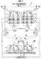
- Fig. 1 is a block diagram showing the configuration of a sound field generation system of an embodiment.
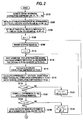
- Fig. 2 is a flowchart illustrating the operation of the sound field generation system of the embodiment.
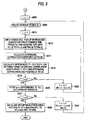
- Fig. 3 is a flowchart further illustrating the operation of the sound field generation system of the embodiment.
- Fig. 4 is a characteristic diagram schematically showing an example of a target interaural correlation coefficient.
- Fig. 5 is a timing chart schematically showing plural test data which are supplied to an interaural correlation coefficient detecting section.
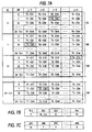
- Fig. 6 is a views showing interaural correlation coefficients and differences which are calculated in optimizing adjustment of delay times of delaying circuits.
- Fig. 7 is a views showing a method of optimumly adjusting the delay times of the delaying circuits.
- Fig. 8 is a views showing a method of optimumly adjusting interaural correlation coefficients, differences, and attenuation factors which are calculated in optimizing adjustment of attenuation factors of attenuator circuits.
- Fig. 9 is a view schematically showing a transfer function of a reproduction sound field.
- Fig. 10 is a view showing the configuration of a sound field generation system according to related art.
- Fig. 11 is a view illustrating a problem of the sound field generation system according to related art.
- Fig. 1 is a block diagram showing a configuration of a sound field generation system 14 of the embodiment, and shows as a typical example a configuration in the case where left and right or two-channel speakers 25 and 26 which are disposed in a living room or the like of the user, and which serve as the sound releasing unit are caused to produce sounds on the basis of left and right or two-channel input audio signals SL and SR.
- the sound field generation system 14 comprises: two so-called input lines CHL and CHR for supplying the input audio signals SL and SR to the speakers 25 and 26; an adjusting circuit 1000 for picking up reproduced sounds generated by the speakers 25 and 26, and feedback controlling characteristics of attenuator circuits 17 and 18 and delaying circuits 19 and 20 which are disposed in the input lines CHL and CHR; and a noise generator 2000.
- the input lines CHL and CHR comprise: digital amplifiers 33 and 34 for left and right or two channels which are configured by a digital signal processor (DSP), and to which the input audio signals SL and SR that have been analog/digital-converted; filter circuits 15 and 16; the attenuator circuits 17 and 18; the delaying circuits 19 and 20; and adders 21, 22, 23, and 24.
- DSP digital signal processor
- the filter circuit 15 is configured by a plurality or n number of band-split digital band pass filters BFL1 to BFLn to which the input audio signal SL is supplied in parallel via the amplifier 33.
- the band pass filters BFL1 to BFLn serving as the first band splitting unit are allocated to split bands which are obtained by splitting the whole audio frequency band into an n number of bands.
- the filter circuit 16 is configured by a plurality or n number of band-split digital band pass filters BFR1 to BFRn.
- the attenuator circuit 17 is configured by a plurality or n number of digital attenuators ATL1 to ATLn which respectively attenuate signals from the band pass filters BFL1 to BFLn and output attenuated signals.
- the attenuation factors of the digital attenuators ATL1 to ATLn can be individually adjusted in a variable manner in accordance with a control by a control section 32 which will be described later.
- the attenuator circuit 18 is configured by a plurality or n number of digital attenuators ATR1 to ATRn which respectively attenuate signals from the band pass filters BFR1 to BFRn in accordance with a control by the control section 32 which will be described later, and output attenuated signals.
- the delaying circuit 19 comprises a plurality or n number of digital delay elements ZL1 to ZLn, individually delays the signals from the band pass filters BFL1 to BFLn, and outputs delayed signals.
- the delaying circuit 20 comprises a plurality or n number of digital delay elements ZR1 to ZRn, and individually delays the signals from the band pass filters BFR1 to BFRn, and outputs delayed signals.
- the delaying amounts (delay times) of the delay elements ZL1 to ZLn and ZR1 to ZRn can be adjusted in accordance with instructions from the control section 32 which will be described later.
- the adder 21 adds the n signals output from the delay elements ZL1 to ZLn together, and supplies a signal SADDL obtained by the addition to the adder 24.
- the adder 22 adds the n signals output from the delay elements ZR1 to ZRn together, and supplies a signal SADDR obtained by the addition to the adder 23.
- the adder 23 adds the input audio signal SL supplied via the amplifier 33, and the signal SADDR, and supplies a signal SDVL obtained by the addition to the speaker 25.
- the adder 24 adds the input audio signal SR supplied via the amplifier 34, and the signal SADDL, and supplies a signal SDVR obtained by the addition to the speaker 26.
- an A/D converter and an output power amplifier are connected between the adder 23 and the speaker 25 so that the signal SDVL which has undergone the digital signal processing is converted into an analog signal and then power-amplified to be supplied to the speaker 25.
- an A/D converter and an output power amplifier are connected between the adder 24 and the speaker 26 so that the signal SDVR is converted into an analog signal and then power-amplified to be supplied to the speaker 26.
- the noise generator 2000 outputs uncorrelated noises SNZ of a uniform level over the whole audio frequency band, in sound field adjustment which will be described later, and supplies the noises to the amplifiers 33 and 34 via a switching circuit which is not shown. Specifically, in normal audio reproduction, the input audio signals SL and SR are supplied to the amplifiers 33 and 34, and, in the sound field adjustment which will be described later, the uncorrelated noises SNZ are supplied in place of the input audio signals SL and SR to the amplifiers 33 and 34.
- the adjusting circuit 1000 is configured by: filter circuits 29 and 30, and an interaural correlation coefficient detecting section 31 which are formed by a digital signal processor (DSP); and the control section 32 comprising a microprocessor (MPU).
- the circuit further comprises microphones 27 and 28 which pick up reproduced sounds released from the speakers 25 and 26 at respective listening positions (substantially corresponding to the positions of the ears) of the listener.
- the filter circuit 29 is configured in the same manner as the filter circuit 15 which is disposed in the input line CHL. Namely, the filter circuit 29 is configured by a plurality or n number of band-split digital band pass filters BFL1' to BFLn' having the same characteristics as those of the band-split digital band pass filters BFL1 to BFLn of the filter circuit 15.
- a pick-up signal PL which is output from the microphone 27 is supplied in parallel to the band pass filters BFL1' to BFLn' serving as the second band splitting unit.
- the filter circuit 30 has the same configuration as the filter circuit 16 which is disposed in the input line CHR, and is configured by a plurality or n number of band-split digital band pass filters BFR1' to BFRn' having the same characteristics as those of the band-split digital band pass filters BFR1 to BFRn of the filter circuit 16.
- a pick-up signal PR which is output from the microphone 28 is supplied in parallel to the band pass filters BFR1' to BFRn' serving as the second band splitting unit.
- the pick-up signals PL and PR are analog/digital-converted by A/D converters, and then supplied to the filter circuits 29 and 30.
- Fig. 2 shows the operation of adjusting the delay times of the delay elements ZL1 to ZLn and ZR1 to ZRn disposed in the delaying circuits 19 and 20, and Fig. 3 shows that of adjusting the attenuation factors of the digital attenuators ATL1 to ATLn and ATR1 to ATRn disposed in the attenuator circuits 17 and 18.
- step S100 the control section 32 initializes the interaural correlation coefficients ⁇ RL' (T1, T2, ..., Tn) of a specific concert hall or the like which is designated by the user.
- the control section 32 previously stores data of interaural correlation coefficients ⁇ RL' which are acquired from transfer functions (frequency characteristics) of, for example, famous concert halls, and also data of an interaural correlation coefficient ⁇ RL' of each of plural concert halls.
- the interaural correlation coefficient ⁇ RL' (T1, T2, ..., Tn) of the designated specific concert hall is initialized.
- the initialized interaural correlation coefficient ⁇ RL' (T1, T2, ..., Tn) is called the target interaural correlation coefficient, and, as shown in Fig. 4, is a set of coefficient data T1, T2, ..., Tn corresponding to the center frequencies of the band-split digital band pass filters BFL1' to BFLn' and BFR1' to BFRn' which are disposed at the n number in the filter circuits 29 and 30.
- step S102 the attenuation factors of all the digital attenuators ATL1 to ATLn and ATR1 to ATRn are initialized to 0 dB, and, in step S104, the delay times of all the delay elements ZL1 to ZLn and ZR1 to ZRn are initialized to 0 sec.
- step S106 a variable q is set to "1" in order to designate the first storage region Q1 of an m number of storage regions Q1 to Qm which will be described later.
- a variable i is set to "1".
- the variable i indicates the order in the case where the delay times of the delay elements ZR1 to ZRn are changed in a step of a predetermined value ⁇ .
- the variable q designates the m number of storage regions Q1 to Qm, and indicates the order in the case where the delay times of the delay elements ZL1 to ZLn are changed in a step of the predetermined value ⁇ .
- step S112 the noise generator 2000 supplies the uncorrelated noises SNZ of the whole audio frequency band to the amplifiers 33 and 34, to cause the speakers 25 and 26 to generate sounds.
- the microphones 27 and 28 pick up reproduced sounds released from the speakers 25 and 26.
- test data DL1(t) to DLn(t) and DR1(t) to DRn(t) which are band-split by passing the pick-up signals PL and PR that are obtained as a result of the picking operation, through the band-split digital band pass filters BFL1' to BFLn' and BFR1' to BFRn' are supplied to the interaural correlation coefficient detecting section 31.
- variable t in the test data DL1(t) to DLn(t) and DR1(t) to DRn(t) indicates that the data are obtained at each reciprocal (sampling period) 1/f of the sampling frequency f which is set on the basis of the sampling theorem. As schematically shown in Fig.
- test data DL1(t) consist of a Tw ⁇ f number of data
- test data DR1(t) consist of a Tw ⁇ f number of data
- other DL2(t) to DLn(t) and DR2(t) to DRn(t) consist of a Tw ⁇ f number of data, respectively.
- test data DL1(t) to DLn(t) are data of sounds which are modulated by spatial transfer functions H12 and H21 between the speakers 25 and 26 and the microphone 27, and the test data DR1(t) to DRn(t) are data of sounds which are modulated by spatial transfer functions H11 and H22 between the speakers 25 and 26 and the microphone 28.
- step S114 the interaural correlation coefficient detecting section 31 calculates an interaural correlation coefficient C11 between the test data DL1(t) and DR1(t), and an interaural correlation coefficient C12 between the test data DL1(t) and DR1(t) by Ex. (1) below.
- variable j of the interaural correlation coefficient Cij indicates the order of 1 to n of the band-split digital band pass filters BFL1' to BFLn' and BFR1' to BFRn'
- the variable i indicates the order in the case where the delay times of the delay elements ZR1 to ZRn are changed in a step of the predetermined value ⁇ .
- the symbol ⁇ > in Ex. (1) indicates an ensemble mean.
- step S116 differences (T1 - C11), (T2 - C12), ..., (Tn - C1n) between the target interaural correlation coefficients (T1, T2, ..., Tn) and the interaural correlation coefficients (C11, C12, ..., C1n) obtained in step S114 are calculated. Namely, as shown in the right side of Fig. 6A, the differences (T1 - C11), (T2 - C12), ..., (Tn - C1n) corresponding to the interaural correlation coefficients (C11, C12, ..., C1n) are obtained.
- step S118 interaural correlation coefficients (C11, C12, ..., C1n) to (Cm1, Cm2, ..., Cmn) in the case where the delay times dL of the delay elements ZL1 to ZLn are fixed to 0 sec. and the delay times dR of the delay elements ZR1 to ZRn are gradually increased from 0 sec. in a step of ⁇ sec. are obtained as shown in the left side of Fig. 6A.
- step S124 the interaural correlation coefficients and the differences shown in Fig. 6B are obtained in the case where the delay times dL of the delay elements ZL1 to ZLn are fixed to ⁇ sec. and the delay times dR of the delay elements ZR1 to ZRn are gradually increased from 0 sec. in a step of ⁇ sec., and the interaural correlation coefficients and the differences shown in Fig. 6C are obtained in the case where the delay times dL of the delay elements ZL1 to ZLn are fixed to 2 ⁇ ⁇ sec. and the delay times dR of the delay elements ZR1 to ZRn are gradually increased from 0 sec.
- the judging and setting processes are performed in the following manner.
- the optimum delay times of the other delay elements are judged and set in the same manner.
- Steps S206 to S228 of Fig. 3 correspond to steps S106 to S128 of Fig. 2. Namely, the attenuation factors of the digital attenuators ATL1 to ATLn and ATR1 to ATRn are adjusted by processes similar to the above-described processes of obtaining the optimum delay times of the delay elements ZL1 to ZLn and ZR1 to ZRn.
- variable r designates the p number of storage regions Q1 to Qp, and indicates the order in the case where the attenuation factors of the digital attenuators ATL1 to ATLn of the delaying circuit 19 are changed in a step of a predetermined value (-G) (decibels).
- the variable i indicates the order in the case where the attenuation factors of the digital attenuators ATR1 to ATRn of the delaying circuit 20 are changed in a step of the predetermined value (-G) (decibels).
- steps S206 to S2266 the processes are performed while the delay elements ZL1 to ZLn and ZR1 to ZRn are set to the above-mentioned optimum delay times, the attenuation factors AL of the digital attenuators ATL1 to ATLn are sequentially changed correspondingly with the variable r or to 0, -G, -2 ⁇ G, ..., -(m - 1) ⁇ G, and the attenuation factors AR of the digital attenuators ATR1 to ATRn are sequentially changed correspondingly with the variable i or to 0, -G, -2 ⁇ G, ..., -(m - 1) ⁇ G.
- the interaural correlation coefficients Cij and the differences [Tj - Cij] associated with the attenuation factors AL and AR are calculated.
- the differences [Tj - Cij] are stored into the storage regions Q1 to Qp with being associated with the attenuation factors AL and AR as shown in Fig. 8A.
- step S2208 on the basis of the differences [Tj - Cij] stored in the storage regions Q1 to Qp, the optimum attenuation factors of the digital attenuators ATL1 to ATLn and ATR1 to ATRn are judged and set.
- the optimum attenuation factors of the digital attenuators ATL1 to ATLn and ATR1 to ATRn are judged in the following manner.
- the optimum attenuation factors of the other digital attenuators are judged and set in the same manner.
- -G is judged as the optimum attenuation factor of the digital attenuator ATRn
- the optimum attenuation factors are set as shown in Figs. 8B and 8C.
- step S2208 When the attenuation factors of all the digital attenuators ATL1 to ATLn and ATR1 to ATRn have been adjusted by the process of step S228, the operation of the noise generator 2000 is stopped, and the input audio signals SL and SR are enabled to be input, thereby completing the sound field adjustment process.
- the attenuation factors of the attenuator circuits 17 and 18, and the delay times of the delaying circuits 19 and 20 are set so as to approximate the interaural correlation coefficient ⁇ RL which is actually acquired from the reproduced sounds, to the interaural correlation coefficient ⁇ RL' of a specific concert hall or the like.
- the speakers 25 and 26 are caused to generate sounds on the basis of the input audio signals SL and SR after the sound field adjustment, a reproduction sound field where spatial sound impression similar to that in the specific concert hall is obtained can be generated even in the living room or the like of the user (listener).
- speakers are caused to generate sounds by passing a stationary random signal of the narrow band through the band pass filters which are set to a narrow band, and an actual interaural correlation coefficient is obtained from reproduced sounds which are generated by the sounding. Consequently, there may arise a case where an approximation error occurs when a reproduction sound field in a listening room of the listener or the like is approximated to an interaural correlation coefficient of a concert hall or the like.
- the uncorrelated noises SNZ of the whole audio frequency band are used as the input signal for adjustment, and the uncorrelated noises SNZ are passed through all of the band pass filters BFL1 to BFLn and BFR1 to BFRn, the digital attenuators ATL1 to ATLn and ATR1 to ATRn, and the digital delay elements ZL1 to ZLn and ZR1 to ZRn, and then supplied to the speakers 25 and 26.
- the actual interaural correlation coefficient ⁇ RL is obtained.
- the interaural correlation coefficient ⁇ RL is actually obtained under the same conditions as those in usual reproduction in which the speakers 25 and 26 are caused to generate sounds by the input audio signals SL and SR.
- the approximation error can be largely reduced, so that the target sound field where spatial sound impression simulating that in a specific concert hall or the like is obtained can be generated.
- the uncorrelated noises SNZ are used as the input signal in the adjustment.
- the invention is not restricted to this.
- any appropriate signal may be used as far as the signal has signal components over the whole audio frequency band.
- the filter circuits 15 and 16, the attenuator circuits 17 and 18, the delaying circuits 19 and 20, and the adders 21 to 24 are disposed in the input lines CHL and CHR for two channels.
- a filter circuit, an attenuator circuit, a delaying circuit, and an adder may be disposed only in one of the input lines.
- a configuration in which the filter circuit 16, the attenuator circuit 18, the delaying circuit 20, and the adder 22 are omitted, the outputs of the amplifiers 33 and 34 are supplied to the adder 23, and the output of the adder 21 and that of the amplifier 34 are supplied to the adder 24 may be employed. Also in the configuration, a sound field where spatial sound impression is obtained can be generated by reproduced sounds released from the speakers 25 and 26.
- the left and right or two-channel input audio signals SL and SR are supplied to enable the speakers 25 and 26 to perform stereophonic reproduction.
- the invention is not restricted to this. Even when a monophonic audio signal is supplied as the audio signals SL and Sr, a reproduction sound field where spatial sound impression is obtained can be generated.
- the two-channel stereophonic audio system has been described.
- the invention can be applied also to a so-called multi-channel audio system having a larger number of channels.
- the speakers 25 and 26 are caused to generate sounds in the sound field adjustment
- the interaural correlation coefficient is acquired on the basis of the reproduced sounds which are actually modulated by the transfer functions (frequency characteristics) H11, H12, H21, and H22 of the spaces such as the living room of the user, and the attenuation factors of the digital attenuators ATL1 to ATLn and ATR1 to ATRn, and the delay times of the delay elements ZL1 to ZLn and ZR1 to ZRn are optimized on the basis of the interaural correlation coefficient.
- the speakers 25 and 26 may not be caused to generate sounds, and the reproduced sounds which are modulated by the transfer functions H11, H12, H21, and H22 of the living room or the like may not be picked up.
- transfer function data [H] in the form of a regular matrix and indicative of the transfer functions H11, H12, H21, and H22 of the space such as the living room may be previously stored in a predetermined storage region of the control section 32, and the attenuation factors of the digital attenuators ATL1 to ATLn and ATR1 to ATRn, and the delay times of the delay elements ZL1 to ZLn and ZR1 to ZRn may be optimized by simulation.
- a first modification of the embodiment may be configured in the following manner.
- the sound field adjustment process which has been described with reference to Figs. 2 and 3, when the attenuation factors of all the digital attenuators ATL1 to ATLn and ATR1 to ATRn are set to 0 dB and the delay times of all the delay elements ZL1 to ZLn and ZR1 to ZRn are set to 0 sec., the frequency characteristics of the signals SDVL and SDVR supplied to the speakers 25 and 26, and the pick-up signals PL and PR picked-up by the microphones 27 and 28 are calculated.
- a transfer function [H] of the space configured by the speakers 25 and 26, the living room, and the like is acquired, and the data [H] of the transfer function are stored in a predetermined storage region of the control section 32. Namely, transfer function data [H] such as shown in Fig. 9 are previously stored.
- the output signals SDVL and SDVR of the adders 23 and 24 are not supplied to the speakers 25 and 26, and the pick-up signals PL and PR are calculated by simulation based on Ex. (2) below. In other words, pseudo pick-up signals PL and PR are acquired by simulation.
- test data DLl(t) to DLn(t) and DR1(t) to DRn(t) are calculated by applying the calculated pick-up signals PL and PR to the filter circuits 29 and 30.
- the interaural correlation coefficients Cij and the differences [Tj - Cij] are calculated on the basis of the test data DL1(t) to DLn(t) and DR1(t) to DRn(t).
- the attenuation factors of the digital attenuators ATL1 to ATLn and ATR1 to ATRn, and the delay times of the delay elements ZL1 to ZLn and ZR1 to ZRn are optimized on the basis of the differences [Tj - Cij].
- the output signals SDVL and SDVR of the adders 23 and 24 are not supplied to the speakers 25 and 26, the pseudo pick-up signals PL and PR are calculated by simulation based on Ex. (2) below, and the pick-up signals PL and PR which are acquired by the calculation are used as the actual pick-up signals to be applied to the filter circuits 29 and 30.
- the pseudo pick-up signals PL and PR which are acquired by the simulation are applied to the filter circuits 29 and 30 to further acquire the test data DL1(t) to DLn(t) and DR1(t) to DRn(t).
- transfer function data [H] including the frequency characteristics of the space of the living room and the like and those of the filter circuits 29 and 30 may be previously stored, the output signals SDVL and SDVR of the adders 23 and 24 may be applied to the transfer function data [H] to directly acquire test data DL1(t) to DLn(t) and DR1(t) to DRn(t), and the interaural correlation coefficient may be calculated on the basis of the test data DL1(t) to DLn(t) and DR1(t) to DRn(t).
- transfer function data [H] of the space configured by the speakers 25 and 26, the living room of the user, and the like are previously stored in a predetermined storage region of the control section 32.
- the pick-up signals PL and PR may be calculated from the beginning by simulation based on Ex. (2) above.
- the pick-up signals PL and PR which are acquired by the calculation may be used as the actual pick-up signals to be applied to the filter circuits 29 and 30.
- the speakers 25 and 26 are caused to generate sounds in the first sound field adjustment.
- sound field adjustment is performed without causing the speakers 25 and 26 to generate sounds, and by only simulation using the transfer function data [H] which are previously stored.
- a reproduction sound field where the user can receive spatial sound impression similar to that obtained in the case where the user listens to music in a desired concert hall can be provided simply by selectively designating a transfer function suitable for the living room or the like of the user.
- the microphones 27 and 28 shown in Fig. 1 can be eliminated.
- transfer function data [H] including the frequency characteristics of the space of the living room and the like and those of the filter circuits 29 and 30 may be previously stored
- the output signals SDVL and SDVR of the adders 23 and 24 may be applied to the transfer function data [H] to directly acquire test data DL1(t) to DLn(t) and DR1(t) to DRn(t)
- interaural correlation coefficient may be calculated on the basis of the test data DL1(t) to DLn(t) and DR1(t) to DRn(t).
- the input signal is supplied to the sound releasing units through the first band splitting units and the delaying units, and reproduced sounds are picked up.
- Interaural correlation is calculated on the basis of band-split outputs which are obtained by band-splitting the reproduced sounds by the second band splitting units having the same bandwidths as those of the first band splitting units. Based on a result of the calculation, the delaying amounts of the delaying units which are disposed in the first band splitting unit, respectively, are controlled. Therefore, the result of the calculation of the interaural correlation contains no influence between the split bands, and the target reproduction sound field can be realized with high accuracy.
- the system is configured so that the attenuation factor adjusting units is disposed in the delaying units, respectively and the attenuation factors of the attenuation factor adjusting units are controlled on the basis of the calculation result of the calculating unit.
- the delaying amount and amplitude controls are conducted on the input signal of the respective bands set by the first band splitting units. Therefore, the target reproduction sound field can be generated with higher accuracy.
- the system further comprises the storage unit for storing data indicative of transfer functions of spaces between the sound releasing unit and listening positions at which reproduced sounds output from the sound releasing units are received, and which correspond to the ears, respectively.
- the signal supplied from the input lines toward the sound releasing units is subjected to a modulation process on the basis of data indicative of the transfer functions, to acquire modulated data corresponding to the reproduced sounds at the listening positions, interaural correlation at the listening positions is calculated on the basis of the modulated data, and delaying amounts of the delaying units are controlled on the basis of a result of the calculation. Even when sounds released from the sound releasing units are not actually picked up by sound picking units such as microphones, therefore, the delaying amounts of the delaying units can be optimized.
- the attenuation factor adjusting units are disposed in the delaying unit, respectively, and the attenuation factors of the attenuation factor adjusting units are controlled on the basis of the calculation result of interaural correlation at the listening positions acquired by simulation. Therefore, not only optimization of the delaying amounts in the input lines, but also optimum control of the amplitudes can be performed, so that the target reproduction sound field can be generated with higher accuracy. Moreover, improvement of convenience of the user and the like can be enabled.
Landscapes
- Physics & Mathematics (AREA)
- Engineering & Computer Science (AREA)
- Acoustics & Sound (AREA)
- Signal Processing (AREA)
- Stereophonic System (AREA)
Applications Claiming Priority (2)
| Application Number | Priority Date | Filing Date | Title |
|---|---|---|---|
| JP2000130623 | 2000-04-28 | ||
| JP2000130623A JP3889202B2 (ja) | 2000-04-28 | 2000-04-28 | 音場生成システム |
Publications (2)
| Publication Number | Publication Date |
|---|---|
| EP1150548A2 true EP1150548A2 (de) | 2001-10-31 |
| EP1150548A3 EP1150548A3 (de) | 2003-04-23 |
Family
ID=18639678
Family Applications (1)
| Application Number | Title | Priority Date | Filing Date |
|---|---|---|---|
| EP01303775A Withdrawn EP1150548A3 (de) | 2000-04-28 | 2001-04-25 | Schallfelderzeungssystem |
Country Status (3)
| Country | Link |
|---|---|
| US (1) | US6621906B2 (de) |
| EP (1) | EP1150548A3 (de) |
| JP (1) | JP3889202B2 (de) |
Families Citing this family (9)
| Publication number | Priority date | Publication date | Assignee | Title |
|---|---|---|---|---|
| JP4171675B2 (ja) * | 2003-07-15 | 2008-10-22 | パイオニア株式会社 | 音場制御システム、および音場制御方法 |
| GB2423449B (en) * | 2005-02-21 | 2009-10-07 | British Broadcasting Corp | Signal meter for digital systems |
| WO2006092995A1 (ja) * | 2005-03-01 | 2006-09-08 | Pioneer Corporation | 音響再生装置 |
| KR100656957B1 (ko) * | 2006-01-10 | 2006-12-14 | 삼성전자주식회사 | 최적 청취 범위를 확장하는 바이노럴 시스템의 동작 방법및 그 방법을 채용한 바이노럴 시스템 |
| US20070253561A1 (en) * | 2006-04-27 | 2007-11-01 | Tsp Systems, Inc. | Systems and methods for audio enhancement |
| WO2013016500A1 (en) * | 2011-07-28 | 2013-01-31 | Thomson Licensing | Audio calibration system and method |
| CN106303821A (zh) * | 2015-06-12 | 2017-01-04 | 青岛海信电器股份有限公司 | 串音消除方法与系统 |
| US9749741B1 (en) * | 2016-04-15 | 2017-08-29 | Amazon Technologies, Inc. | Systems and methods for reducing intermodulation distortion |
| JP2024001902A (ja) * | 2022-06-23 | 2024-01-11 | フォルシアクラリオン・エレクトロニクス株式会社 | 音響処理システム及び音響処理方法 |
Family Cites Families (6)
| Publication number | Priority date | Publication date | Assignee | Title |
|---|---|---|---|---|
| EP0553832B1 (de) * | 1992-01-30 | 1998-07-08 | Matsushita Electric Industrial Co., Ltd. | Schallfeldsteuerungssystem |
| JP3496230B2 (ja) * | 1993-03-16 | 2004-02-09 | パイオニア株式会社 | 音場制御システム |
| US5684881A (en) * | 1994-05-23 | 1997-11-04 | Matsushita Electric Industrial Co., Ltd. | Sound field and sound image control apparatus and method |
| JP3547813B2 (ja) | 1994-10-31 | 2004-07-28 | パイオニア株式会社 | 音場生成装置 |
| JP3976360B2 (ja) * | 1996-08-29 | 2007-09-19 | 富士通株式会社 | 立体音響処理装置 |
| US6035045A (en) * | 1996-10-22 | 2000-03-07 | Kabushiki Kaisha Kawai Gakki Seisakusho | Sound image localization method and apparatus, delay amount control apparatus, and sound image control apparatus with using delay amount control apparatus |
-
2000
- 2000-04-28 JP JP2000130623A patent/JP3889202B2/ja not_active Expired - Fee Related
-
2001
- 2001-04-25 EP EP01303775A patent/EP1150548A3/de not_active Withdrawn
- 2001-04-27 US US09/842,640 patent/US6621906B2/en not_active Expired - Fee Related
Also Published As
| Publication number | Publication date |
|---|---|
| JP3889202B2 (ja) | 2007-03-07 |
| JP2001314000A (ja) | 2001-11-09 |
| US6621906B2 (en) | 2003-09-16 |
| US20020044664A1 (en) | 2002-04-18 |
| EP1150548A3 (de) | 2003-04-23 |
Similar Documents
| Publication | Publication Date | Title |
|---|---|---|
| US7409067B2 (en) | Method and apparatus for adjusting frequency characteristic of signal | |
| US6901148B2 (en) | Automatic sound field correcting device | |
| US5450494A (en) | Automatic volume controlling apparatus | |
| JP3955265B2 (ja) | 指向性コントローラおよび補聴器を制御する方法 | |
| EP0666556B1 (de) | Schallfeldkontrollegerät und Kontrolleverfahren | |
| EP2096883A2 (de) | Raumklangausgabeanordnung und Raumklangausgabeverfahren | |
| EP1545154A2 (de) | Virtuelles Raumklang Gerät | |
| US20090110218A1 (en) | Dynamic equalizer | |
| US6658117B2 (en) | Sound field effect control apparatus and method | |
| US20050265558A1 (en) | Method and circuit for enhancement of stereo audio reproduction | |
| EP1126744A2 (de) | Automatisches schallfeld-korrektursystem | |
| US6970569B1 (en) | Audio processing apparatus and audio reproducing method | |
| EP1126746A2 (de) | Anordnung zur automatischen Schallfeldkorrektur und Schallfeldkorrektur-Verfahren | |
| KR20120066006A (ko) | 스테레오포닉 또는 슈도―스테레오포닉 오디오 신호의 최적화 장치 및 방법 | |
| US8023662B2 (en) | Reverberation adjusting apparatus, reverberation correcting method, and sound reproducing system | |
| EP1126743B1 (de) | Schallfeld-korrekturverfahren in einem Audiosystem | |
| EP1150548A2 (de) | Schallfelderzeungssystem | |
| US5604810A (en) | Sound field control system for a multi-speaker system | |
| EP1499161A2 (de) | Kontrollsystem für ein Schallfeld und zugehöriges Kontrollverfahren | |
| US8553893B2 (en) | Sound processing device, speaker apparatus, and sound processing method | |
| US7567682B2 (en) | Audio processing apparatus | |
| KR102473131B1 (ko) | 노이즈 감쇠 기능 및 공간 효과 구현 기능을 제공하는 음향 처리 시스템 | |
| US8116468B2 (en) | Stereophonic sound reproduction device | |
| EP1126745B1 (de) | Schallfeld-korrekturverfahren in einem Audiosystem | |
| US20050053246A1 (en) | Automatic sound field correction apparatus and computer program therefor |
Legal Events
| Date | Code | Title | Description |
|---|---|---|---|
| PUAI | Public reference made under article 153(3) epc to a published international application that has entered the european phase |
Free format text: ORIGINAL CODE: 0009012 |
|
| AK | Designated contracting states |
Kind code of ref document: A2 Designated state(s): AT BE CH CY DE DK ES FI FR GB GR IE IT LI LU MC NL PT SE TR |
|
| AX | Request for extension of the european patent |
Free format text: AL;LT;LV;MK;RO;SI |
|
| PUAL | Search report despatched |
Free format text: ORIGINAL CODE: 0009013 |
|
| AK | Designated contracting states |
Designated state(s): AT BE CH CY DE DK ES FI FR GB GR IE IT LI LU MC NL PT SE TR |
|
| AX | Request for extension of the european patent |
Extension state: AL LT LV MK RO SI |
|
| 17P | Request for examination filed |
Effective date: 20031008 |
|
| AKX | Designation fees paid |
Designated state(s): DE FR GB |
|
| GRAP | Despatch of communication of intention to grant a patent |
Free format text: ORIGINAL CODE: EPIDOSNIGR1 |
|
| STAA | Information on the status of an ep patent application or granted ep patent |
Free format text: STATUS: THE APPLICATION IS DEEMED TO BE WITHDRAWN |
|
| 18D | Application deemed to be withdrawn |
Effective date: 20081105 |