EP1150916B1 - Hebezeug - Google Patents
Hebezeug Download PDFInfo
- Publication number
- EP1150916B1 EP1150916B1 EP00993403A EP00993403A EP1150916B1 EP 1150916 B1 EP1150916 B1 EP 1150916B1 EP 00993403 A EP00993403 A EP 00993403A EP 00993403 A EP00993403 A EP 00993403A EP 1150916 B1 EP1150916 B1 EP 1150916B1
- Authority
- EP
- European Patent Office
- Prior art keywords
- wheel
- drive shaft
- drive wheel
- load
- disc
- Prior art date
- Legal status (The legal status is an assumption and is not a legal conclusion. Google has not performed a legal analysis and makes no representation as to the accuracy of the status listed.)
- Expired - Lifetime
Links
Images


Classifications
-
- B—PERFORMING OPERATIONS; TRANSPORTING
- B66—HOISTING; LIFTING; HAULING
- B66D—CAPSTANS; WINCHES; TACKLES, e.g. PULLEY BLOCKS; HOISTS
- B66D5/00—Braking or detent devices characterised by application to lifting or hoisting gear, e.g. for controlling the lowering of loads
- B66D5/02—Crane, lift hoist, or winch brakes operating on drums, barrels, or ropes
- B66D5/12—Crane, lift hoist, or winch brakes operating on drums, barrels, or ropes with axial effect
- B66D5/14—Crane, lift hoist, or winch brakes operating on drums, barrels, or ropes with axial effect embodying discs
-
- B—PERFORMING OPERATIONS; TRANSPORTING
- B66—HOISTING; LIFTING; HAULING
- B66D—CAPSTANS; WINCHES; TACKLES, e.g. PULLEY BLOCKS; HOISTS
- B66D3/00—Portable or mobile lifting or hauling appliances
- B66D3/12—Chain or like hand-operated tackles with or without power transmission gearing between operating member and lifting rope, chain or cable
- B66D3/16—Chain or like hand-operated tackles with or without power transmission gearing between operating member and lifting rope, chain or cable operated by an endless chain passing over a pulley or a sprocket
Definitions
- the invention relates to a hoist according to the features in the preamble of claim 1.
- Hoists of the type in question serve in particular the vertical shifting of loads. They include one Drive wheel, which is often designed as a sprocket and by means of a manually manageable round link chain in can be turned in both directions. Instead of one Sprocket can also kick a gear. Furthermore can the drive wheel as a clutch wheel to a motor shaft be trained.
- a load wheel designed as a chain wheel is via a round link chain with a load suspension device, such as a crane hook.
- the housing of the hoist is usually one Provide hooks over which there are suitable abutments can be hung.
- a load pressure brake In the housing are arranged axially one behind the other the drive wheel, a load pressure brake, the load wheel and arranged a gear, the gear often as Planetary gear is formed.
- the drive wheel is seated at one end of a drive shaft which is the load pressure brake and penetrated the load wheel. At the other end of the The drive shaft is the gearbox, which then is connected to the load wheel to transmit torque.
- the load pressure brake consists of one Ratchet disc, two lying on either side of the ratchet disc Friction discs and two hinged to the housing Pawls together, under the influence of Leg springs are pressed against the ratchet disc.
- the Both friction disks kick the ratchet disk once and on the other hand with one fixed to the shaft Thrust washer or the drive wheel in a frictional Connection.
- the drive wheel is on a thread axially displaceable at one end of the drive shaft.
- the other end of the drive shaft is with two gears coupled, which in turn is smaller in diameter toothed pinions are connected to a gearwheel, which has an internal toothing in which a pinion fits, which is connected to the load wheel.
- the load pressure brake does the job of the hoist to keep the load carried at the respective height if that Drive wheel stands still. Then the drive wheel is over the Friction discs and the ratchet disc on the pressure disc pressed. The pawls are in the circumferential Notches in the ratchet disc.
- the invention is the The task is to create a hoist that is easier built, designed to be less sensitive to noise and less noisy is.
- the drive wheel is opposite the drive shaft limited rotation, but axially immovable arranged.
- the drive wheel is also included a brake disc limitedly rotatably coupled, which in turn on a threaded portion of the drive shaft is axially displaceable. Between the brake disc and a thrust washer attached to the housing of the hoist there is a friction disc.
- the drive wheel rotated clockwise. After a predetermined angle of rotation, over which the drive wheel faces the drive shaft can rotate freely, the free rotation lifted and the drive shaft directly via the handwheel driven without the brake being loaded. by virtue of of the right-hand thread section is used for Rotate the brake disc clockwise from the friction disc released so that the braking effect is canceled becomes.
- the drive wheel To lower the load, the drive wheel must go counterclockwise be rotated. After a predetermined angle of rotation the drive wheel is coupled to the Brake disc. This is due to the right-hand thread section on this towards the drive wheel axially displaced and the contact with the thrust washer over the friction disc. After that, the Load according to the given angle of rotation between run after the drive wheel and the brake disc and will then braked again by the fact that the under Load rotating drive shaft against the brake disc Friction disc and pulling it against the pressure disc.
- the particular advantage of the invention is that it compared to the known design much more precise and works quieter. Also from the number of components the hoist according to the invention is simpler.
- the drive wheel can with a Chain, a rope, a crank or also by means of a Motor driven.
- the rotatability of the drive wheel on the drive shaft is preferred according to the features of claim 2 with Realized using a socket fixed on the drive shaft.
- the socket can be pressed onto the drive shaft his.
- the drive wheel acts with a wing disc connected in a rotationally fixed manner on the drive shaft torque transmitting together. This points the drive wheel has an end projection with its corresponding stop on the wing disc after a predetermined angle of rotation of the drive wheel in Contact and so the wing disc and thus the Drives the drive shaft in rotation.
- the wing disk is also the bushing on the drive shaft fixed in position.
- the wing disc is preferably serrated pushed at the end of the drive shaft and using a Mother pressed against the socket, which in turn with a radial collar against a shoulder of the drive shaft is pressed.
- the drive wheel is then between this radial collar and the end face facing it the wing disc is guided exactly.
- the wing disc has at least one radially projecting wing that with at least one front projection on the drive wheel interacts.
- Prefers has the wing disc two offset by 180 ° to each other radial wings. Accordingly, are also on the Front of the drive wheel preferably two projections provided, in particular cast in one piece, with the wings work together.
- the limited rotating coupling of the drive wheel with the brake disc is preferred with the features of the claim 4 realized.
- the driving pin summarizes in one, preferably arcuate, segment-like Recess in the side of the drive wheel facing the load wheel. The ends of the recess into which the driving pin engages are then aligned by radially Webs formed. The dragging of the brake disc by the The drive wheel is used to lower the brake disc lift off the thrust washer and thereby the To release the load pressure brake.
- the brake disc by a Drive wheel supporting spring pressed against the thrust washer.
- This spring has the main task, a to generate the initial braking torque. This allows the Response time of the load pressure brake can be shortened.
- 1 denotes a hoist, how it is used for lifting and lowering loads L.
- the hoist 1 points within a not described in detail Housing G arranged axially one behind the other a drive wheel 2, a load pressure brake 3, a load wheel 4 and a transmission 5.
- the drive wheel 2 is on one End 6 of a drive shaft 7 is provided and is about this penetrates the load pressure brake 3 and the load wheel 4 Drive shaft 7 with the other end 8 of the drive shaft 7 located, drifting on the load wheel 4 Transmission 5 can be coupled to transmit torque.
- the drive shaft 7 with a cylindrical Length section 9 provided (Fig. 2), which in a front serration 10 and from the serration 10 merges into an end threaded section 11.
- a cylindrical Length section 9 On the cylindrical length section 9 is one with a radial collar 12 provided socket 13 and up pressed against a shoulder 14 of the drive shaft 7.
- the socket 13 is against with the help of a wing disc 15 the shoulder 14 pressed, in that the Threaded portion 11 a nut 16 is rotated over which the wing disc 15 against the socket 13 and this are pressed against the shoulder 14 (Fig. 1, 2 and 4).
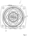
- the wing disk 15 can be seen in particular from FIG. 4. It has a central ring body 17 the 180 ° offset two radially projecting vanes 18 are scheduled.
- the wings 18 each have an arc curved back area 19 and one in a radial plane extending stop surface 20. Die Stop faces 20 of the wings 18 come with projections 21 in contact, which on the free side 22 of the drive wheel 2 are integrally formed.
- the drive wheel 2 has an inner hub 23 with which it between the radial collar 12 of the sleeve 13 and the opposite Face 24 of the wing disc 15 sliding is performed (Fig. 2).
- Internal thread 30 and external thread 31 are right-handed Movement thread trained.
- the brake disc 29 is on the drive wheel 2 facing away Ring-shaped side and contacted a friction disc 32, which in turn on a Thrust washer 33 is pressed on one component of the housing forming cross plate 34 is fixed (Fig. 2).
- the system of the brake disc 29 on the Friction disk 32 and this on the pressure disk 33 is supported by a helical compression spring 35 which overlaps an axial connecting piece 36 of the brake disk 29 and engages in an annular recess 37 of the drive wheel 2.
- the transverse plate 34 of the housing carrying the thrust washer 33 G serves together with one at a parallel distance arranged further cross plate 38 of the rotatable bearing also as a sprocket for a round link chain trained load wheel 4 (Fig. 1 and 2). Camps for the load wheel 4 in the cross plates 34 and 38 are with 39 designated.
- the load wheel 4 is axially spaced on two mutually cylindrical sliding surfaces 40 the drive shaft 7 mounted relatively rotatable. It sums up with an axial nozzle 41 in a gear 42, which in addition the cross plate 33 is non-rotatably seated on this nozzle 41
- the gear 42 meshes with two pinions 43 as part of two gears 44, which in turn with mesh a gear end portion 45 of the drive shaft 7.
- the drive wheel 2 counterclockwise in the direction of arrow PF 3 Figures 1-4 rotated. After a predetermined angle of rotation the drive pin 28 arrives with a web 27 of the drive wheel 2 in contact, so that now the brake disc 29 on the movement thread 31 of the drive shaft 7 displaced and from the friction disc 32 or this is lifted off the thrust washer 33.
- the load L causes then that a relative rotation of the drive shaft 7 to the drive wheel 2, so that the brake disc 29 again according to arrow PF 2 against the friction disc 32 and thus pulled against the thrust washer 33 and the load L is braked.
Landscapes
- Engineering & Computer Science (AREA)
- Mechanical Engineering (AREA)
- Braking Arrangements (AREA)
- Knitting Machines (AREA)
- Conveying And Assembling Of Building Elements In Situ (AREA)
- Jib Cranes (AREA)
- Iron Core Of Rotating Electric Machines (AREA)
- Cage And Drive Apparatuses For Elevators (AREA)
- Transmission Devices (AREA)
Description
- Figur 1
- in der Draufsicht ein Hebezeug;
- Figur 2
- einen vertikalen Längsschnitt durch die Darstellung der Figur 1 entlang der Linie II-II
- Figur 3
- einen vertikalen Querschnitt durch die Darstellung der Figur 1 entlang der Linie III-III und
- Figur 4
- eine Stirnansicht auf die Darstellung der Figur 1 in Richtung des Pfeils IV ohne Deckel.
- 1 -
- Hebezeug
- 2 -
- Antriebsrad
- 3 -
- Lastdruckbremse
- 4 -
- Lastrad
- 5 -
- Getriebe
- 6 -
- Ende von 7
- 7 -
- Antriebswelle
- 8 -
- Ende von 7
- 9 -
- zylindrischer Längenabschnitt von 7
- 10 -
- Kerbverzahnung in 6
- 11 -
- Gewindeabschnitt in 6
- 12 -
- radialer Kragen von 13
- 13 -
- Buchse
- 14 -
- Schulter an 7
- 15 -
- Flügelscheibe
- 16 -
- Mutter
- 17 -
- Ringkörper von 15
- 18 -
- Flügel von 15
- 19 -
- Rückenbereich von 18
- 20 -
- Anschlagfläche
- 21 -
- Vorsprünge an 2
- 22 -
- Seite von 2
- 23 -
- Nabe von 2
- 24 -
- Stirnseite von 15
- 25 -
- Seite von 2
- 26 -
- Aussparungen in 25
- 27 -
- Stege zwischen 26
- 28 -
- Mitnahmestift an 29
- 29 -
- Bremsscheibe
- 30 -
- Innengewinde von 29
- 31 -
- Außengewinde von 7
- 32 -
- Friktionsscheibe
- 33 -
- Druckscheibe
- 34 -
- Querplatte
- 35 -
- Schraubendruckfeder
- 36 -
- Stutzen von 29
- 37 -
- Ringausnehmung in 2
- 38 -
- Querplatte
- 39 -
- Lager für 4
- 40 -
- Gleitflächen an 7
- 41 -
- Stutzen an 4
- 42 -
- Zahnrad
- 43 -
- Zahnritzel
- 44 -
- Zahnräder
- 45 -
- Zahnradendabschnitt von 7
- G -
- Gehäuse v. 1
- L -
- Last
- PF -
- Pfeil
- PF1 -
- Pfeil
- PF2 -
- Pfeil
- PF3 -
- Pfeil
Claims (5)
- Hebezeug, das innerhalb eines Gehäuses in axialer Hinteineinanderanordnung ein Antriebsrad (2), eine Lastdruckbremse (3), ein Lastrad (4) und ein Getriebe (5) aufweist, wobei das an einem Ende (6) einer Antriebswelle (7) vorgesehene Antriebsrad (2) über diese die Lastdruckbremse (3) und das Lastrad (4) durchsetzende Antriebswelle (7) mit dem am anderen Ende (8) der Antriebswelle (7) befindlichen, auf das Lastrad (4) abtreibenden Getriebe (5) drehmomentübertragend koppelbar ist, dadurch gekennzeichnet, dass das Antriebsrad (2) auf der Antriebswelle (7) axial unverschieblich, jedoch begrenzt relativdrehbar gelagert sowie mit einer auf einem Gewindeabschnitt (31) der Antriebswelle (7) axial verschiebbaren und unter Eingliederung einer Friktionsscheibe (32) gegen eine am Gehäuse festgelegte Druckscheibe (33) anpressbaren Bremsscheibe (29) als Bestandteil der Lastdruckbremse (3) begrenzt relativdrehbar ist.
- Hebezeug nach Anspruch 1, dadurch gekennzeichnet, dass das Antriebsrad (2) auf einer auf der Antriebswelle (7) festgelegten Buchse (13) drehbar gelagert ist.
- Hebezeug nach Anspruch 1 oder 2, dadurch gekennzeichnet, dass das Antriebsrad (2) einen stirnseitigen Vorsprung (21) aufweist, der mit einer mit der Antriebswelle (7) drehfest verbundenen Flügelscheibe (15) drehmomentübertragend zusammenwirkt.
- Hebezeug nach einem der Ansprüche 1 bis 3, dadurch gekennzeichnet, dass die Bremsscheibe (29) einen axial ausgerichteten Mitnahmestift (28) aufweist, der in eine segmentartige Aussparung (26) des Antriebsrads (2) in der dem Lastrad (4) zugewandten Seite (25) relativverschiebbar eingreift.
- Hebezeug nach einem der Ansprüche 1 bis 4, dadurch gekennzeichnet, dass die Bremsscheibe (29) durch eine sich an dem Antriebsrad (2) abstützende Feder (35) gegen die Druckscheibe (33) gepresst ist.
Applications Claiming Priority (3)
| Application Number | Priority Date | Filing Date | Title |
|---|---|---|---|
| DE19959999 | 1999-12-13 | ||
| DE19959999A DE19959999C2 (de) | 1999-12-13 | 1999-12-13 | Hebezeug |
| PCT/DE2000/004325 WO2001044100A1 (de) | 1999-12-13 | 2000-12-02 | Hebezeug |
Publications (2)
| Publication Number | Publication Date |
|---|---|
| EP1150916A1 EP1150916A1 (de) | 2001-11-07 |
| EP1150916B1 true EP1150916B1 (de) | 2004-07-14 |
Family
ID=7932435
Family Applications (1)
| Application Number | Title | Priority Date | Filing Date |
|---|---|---|---|
| EP00993403A Expired - Lifetime EP1150916B1 (de) | 1999-12-13 | 2000-12-02 | Hebezeug |
Country Status (16)
| Country | Link |
|---|---|
| US (1) | US6527253B2 (de) |
| EP (1) | EP1150916B1 (de) |
| JP (1) | JP2003516918A (de) |
| KR (1) | KR100417577B1 (de) |
| CN (1) | CN1148314C (de) |
| AT (1) | ATE271017T1 (de) |
| AU (1) | AU759668B2 (de) |
| BR (1) | BR0008168A (de) |
| CA (1) | CA2363082C (de) |
| CZ (1) | CZ291908B6 (de) |
| DE (2) | DE19959999C2 (de) |
| ES (1) | ES2222274T3 (de) |
| PL (1) | PL202461B1 (de) |
| TW (1) | TW555686B (de) |
| WO (1) | WO2001044100A1 (de) |
| ZA (1) | ZA200106542B (de) |
Families Citing this family (8)
| Publication number | Priority date | Publication date | Assignee | Title |
|---|---|---|---|---|
| JP4693506B2 (ja) * | 2005-06-03 | 2011-06-01 | 株式会社キトー | 巻上牽引機 |
| DE102010016267B4 (de) * | 2010-03-31 | 2018-01-11 | Heinrich De Fries Gmbh | Handbetriebener Kettenzug |
| KR101373133B1 (ko) * | 2011-12-21 | 2014-03-13 | 주식회사 두산이노텍 | 다줄 나사가 구비되는 호이스트용 메카니컬 브레이크 및 그 다줄 나사 가공방법 |
| KR101376047B1 (ko) * | 2012-05-10 | 2014-03-18 | 주식회사 코브 인터내셔날 | 안전블럭의 제동장치 |
| PL234340B1 (pl) * | 2018-03-08 | 2020-02-28 | Inst Techniki Gorniczej Komag | Hamulec mechaniczny z możliwością dwukierunkowego ruchu wyjściowego wału napędowego |
| DE102019120036A1 (de) | 2019-07-24 | 2021-01-28 | Columbus Mckinnon Industrial Products Gmbh | Hebezeug |
| CN111302255B (zh) * | 2020-02-11 | 2021-10-22 | 三门核电有限公司 | 一种可电动拉链的手拉葫芦 |
| DE102021101058A1 (de) | 2021-01-19 | 2022-07-21 | Columbus Mckinnon Industrial Products Gmbh | Hebezeug |
Family Cites Families (16)
| Publication number | Priority date | Publication date | Assignee | Title |
|---|---|---|---|---|
| US1572001A (en) * | 1925-03-05 | 1926-02-09 | Wright Mfg Company | Chain hoist |
| US1876954A (en) * | 1929-04-25 | 1932-09-13 | J P Johnson Engineering Compan | Hoist |
| US1993744A (en) * | 1934-06-02 | 1935-03-12 | Morison Inc | Automatic two-way brake for hoists |
| US2403462A (en) * | 1944-02-25 | 1946-07-09 | Yale & Towne Mfg Co | Chain hoist |
| US2417492A (en) * | 1944-07-21 | 1947-03-18 | Hinchcliffe Sidney | Lifting and pulling mechanism |
| US2548846A (en) * | 1947-11-01 | 1951-04-10 | Columbus Mckinnon Chain Corp | Chain hoist |
| FR1193419A (fr) * | 1957-03-28 | 1959-11-03 | Schiess Defries Hebezeug Und K | Frein fonctionnant sous la pression de la charge pour palans, treuils et autres appareils de levage |
| US3090601A (en) * | 1960-11-29 | 1963-05-21 | Columbus Mckinnon Corp | Hoist brake |
| JPS5227808Y2 (de) * | 1973-05-14 | 1977-06-24 | ||
| DE3507724A1 (de) * | 1985-03-05 | 1986-09-25 | Heinrich de Fries GmbH, 4000 Düsseldorf | Lastdruckbremse |
| AU666078B2 (en) * | 1993-07-02 | 1996-01-25 | Elephant Chain Block Company Limited | Manual chain block |
| JP2597289B2 (ja) * | 1993-07-02 | 1997-04-02 | 象印チエンブロック株式会社 | 手動式チェンブロック |
| US5586751A (en) * | 1993-09-14 | 1996-12-24 | Elephant Chain Block Company, Ltd. | Manual chain block |
| US6032928A (en) * | 1997-05-15 | 2000-03-07 | Elephant Chain Block Co., Ltd. | Hand operated chain block having improved hand wheel |
| JP2919810B2 (ja) * | 1997-05-15 | 1999-07-19 | 象印チエンブロック株式会社 | 手動式チェンブロック |
| JP2919809B2 (ja) * | 1997-05-15 | 1999-07-19 | 象印チエンブロック株式会社 | 手動式チェンブロック |
-
1999
- 1999-12-13 DE DE19959999A patent/DE19959999C2/de not_active Expired - Fee Related
-
2000
- 2000-12-02 AT AT00993403T patent/ATE271017T1/de not_active IP Right Cessation
- 2000-12-02 KR KR10-2001-7010158A patent/KR100417577B1/ko not_active Expired - Fee Related
- 2000-12-02 BR BR0008168-0A patent/BR0008168A/pt not_active IP Right Cessation
- 2000-12-02 AU AU28280/01A patent/AU759668B2/en not_active Ceased
- 2000-12-02 CZ CZ20012915A patent/CZ291908B6/cs not_active IP Right Cessation
- 2000-12-02 DE DE50007068T patent/DE50007068D1/de not_active Expired - Fee Related
- 2000-12-02 CN CNB008036608A patent/CN1148314C/zh not_active Expired - Fee Related
- 2000-12-02 CA CA002363082A patent/CA2363082C/en not_active Expired - Fee Related
- 2000-12-02 ES ES00993403T patent/ES2222274T3/es not_active Expired - Lifetime
- 2000-12-02 EP EP00993403A patent/EP1150916B1/de not_active Expired - Lifetime
- 2000-12-02 WO PCT/DE2000/004325 patent/WO2001044100A1/de not_active Ceased
- 2000-12-02 PL PL349263A patent/PL202461B1/pl not_active IP Right Cessation
- 2000-12-02 JP JP2001545194A patent/JP2003516918A/ja active Pending
-
2001
- 2001-02-01 TW TW089126457A patent/TW555686B/zh active
- 2001-08-08 ZA ZA200106542A patent/ZA200106542B/en unknown
- 2001-08-13 US US09/928,871 patent/US6527253B2/en not_active Expired - Fee Related
Also Published As
| Publication number | Publication date |
|---|---|
| ATE271017T1 (de) | 2004-07-15 |
| ES2222274T3 (es) | 2005-02-01 |
| US20020027222A1 (en) | 2002-03-07 |
| KR100417577B1 (ko) | 2004-02-05 |
| DE19959999A1 (de) | 2001-07-05 |
| WO2001044100A1 (de) | 2001-06-21 |
| PL202461B1 (pl) | 2009-06-30 |
| ZA200106542B (en) | 2002-11-08 |
| CN1148314C (zh) | 2004-05-05 |
| DE19959999C2 (de) | 2001-10-11 |
| AU759668B2 (en) | 2003-04-17 |
| EP1150916A1 (de) | 2001-11-07 |
| TW555686B (en) | 2003-10-01 |
| HK1046126A1 (en) | 2002-12-27 |
| AU2828001A (en) | 2001-06-25 |
| KR20010102058A (ko) | 2001-11-15 |
| DE50007068D1 (de) | 2004-08-19 |
| JP2003516918A (ja) | 2003-05-20 |
| CN1340026A (zh) | 2002-03-13 |
| CA2363082C (en) | 2004-11-23 |
| BR0008168A (pt) | 2002-01-22 |
| CZ291908B6 (cs) | 2003-06-18 |
| US6527253B2 (en) | 2003-03-04 |
| CZ20012915A3 (cs) | 2002-03-13 |
| PL349263A1 (en) | 2002-07-01 |
| CA2363082A1 (en) | 2001-06-21 |
Similar Documents
| Publication | Publication Date | Title |
|---|---|---|
| DE2704372C2 (de) | Überlast-Schutzvorrichtung für Hebezeuge | |
| DE2033207B2 (de) | Druckluftschrauber | |
| DE2714452C2 (de) | Überlastschutzeinrichtung für Hebezeuge | |
| DE3509783A1 (de) | Hebezeug mit ueberlastungsschutz | |
| DE1481881A1 (de) | Winde | |
| EP4003897B1 (de) | Hebezeug | |
| DE19959999C2 (de) | Hebezeug | |
| DE2848541B1 (de) | Hydraulische Vorrichtung zum Betrieb eines Aufzuges | |
| DE2821946C2 (de) | ||
| EP3395746B1 (de) | Kettenzug | |
| DE602004006173T2 (de) | Drehmomentgesteuerte Bremse | |
| EP4095083B1 (de) | Anordnung zum ausrichten einer angehobenen last | |
| DE2258833A1 (de) | Treibscheibentriebwerk | |
| EP4281399B1 (de) | Hebezeug | |
| EP4263414B1 (de) | Hebelzug | |
| DE3611893C2 (de) | ||
| DE19734858A1 (de) | Vorderachsabtrieb eines Automatgetriebes | |
| DE10147629B4 (de) | Aufzug | |
| DE102004035222B3 (de) | Sicherheitskurbel zum Heben und Senken von Lasten | |
| DE576345C (de) | Windentrommel fuer Krane, Aufzuege usw | |
| DE2328449C2 (de) | Vorrichtung zum mehrlagigen Aufwickeln von Seilen, Kabeln od. dgl | |
| DE1251154B (de) | Sicherheitsemrichtung fur einen Druckflussigkeitsaxialkolbenmotor | |
| DE3020794C2 (de) | Kippantrieb mit Bremse für warmgängige Gefäße, insbesondere Schlackenkübel | |
| DE120247C (de) | ||
| DE1908363C (de) | Kettenflaschenzug, der gleichzeitig als Zugvorrichtung dient |
Legal Events
| Date | Code | Title | Description |
|---|---|---|---|
| PUAI | Public reference made under article 153(3) epc to a published international application that has entered the european phase |
Free format text: ORIGINAL CODE: 0009012 |
|
| 17P | Request for examination filed |
Effective date: 20010731 |
|
| AK | Designated contracting states |
Kind code of ref document: A1 Designated state(s): AT BE CH CY DE DK ES FI FR GB GR IE IT LI LU MC NL PT SE TR |
|
| AX | Request for extension of the european patent |
Free format text: AL;LT;LV;MK;RO;SI |
|
| GRAP | Despatch of communication of intention to grant a patent |
Free format text: ORIGINAL CODE: EPIDOSNIGR1 |
|
| GRAS | Grant fee paid |
Free format text: ORIGINAL CODE: EPIDOSNIGR3 |
|
| GRAA | (expected) grant |
Free format text: ORIGINAL CODE: 0009210 |
|
| AK | Designated contracting states |
Kind code of ref document: B1 Designated state(s): AT BE CH CY DE DK ES FI FR GB GR IE IT LI LU MC NL PT SE TR |
|
| PG25 | Lapsed in a contracting state [announced via postgrant information from national office to epo] |
Ref country code: FI Free format text: LAPSE BECAUSE OF FAILURE TO SUBMIT A TRANSLATION OF THE DESCRIPTION OR TO PAY THE FEE WITHIN THE PRESCRIBED TIME-LIMIT Effective date: 20040714 Ref country code: IE Free format text: LAPSE BECAUSE OF FAILURE TO SUBMIT A TRANSLATION OF THE DESCRIPTION OR TO PAY THE FEE WITHIN THE PRESCRIBED TIME-LIMIT Effective date: 20040714 Ref country code: CY Free format text: LAPSE BECAUSE OF FAILURE TO SUBMIT A TRANSLATION OF THE DESCRIPTION OR TO PAY THE FEE WITHIN THE PRESCRIBED TIME-LIMIT Effective date: 20040714 Ref country code: TR Free format text: LAPSE BECAUSE OF FAILURE TO SUBMIT A TRANSLATION OF THE DESCRIPTION OR TO PAY THE FEE WITHIN THE PRESCRIBED TIME-LIMIT Effective date: 20040714 |
|
| REG | Reference to a national code |
Ref country code: GB Ref legal event code: FG4D Free format text: NOT ENGLISH |
|
| REG | Reference to a national code |
Ref country code: CH Ref legal event code: EP |
|
| REF | Corresponds to: |
Ref document number: 50007068 Country of ref document: DE Date of ref document: 20040819 Kind code of ref document: P |
|
| REG | Reference to a national code |
Ref country code: IE Ref legal event code: FG4D Free format text: GERMAN |
|
| GBT | Gb: translation of ep patent filed (gb section 77(6)(a)/1977) |
Effective date: 20040908 |
|
| PG25 | Lapsed in a contracting state [announced via postgrant information from national office to epo] |
Ref country code: GR Free format text: LAPSE BECAUSE OF FAILURE TO SUBMIT A TRANSLATION OF THE DESCRIPTION OR TO PAY THE FEE WITHIN THE PRESCRIBED TIME-LIMIT Effective date: 20041014 Ref country code: DK Free format text: LAPSE BECAUSE OF FAILURE TO SUBMIT A TRANSLATION OF THE DESCRIPTION OR TO PAY THE FEE WITHIN THE PRESCRIBED TIME-LIMIT Effective date: 20041014 Ref country code: SE Free format text: LAPSE BECAUSE OF FAILURE TO SUBMIT A TRANSLATION OF THE DESCRIPTION OR TO PAY THE FEE WITHIN THE PRESCRIBED TIME-LIMIT Effective date: 20041014 |
|
| PG25 | Lapsed in a contracting state [announced via postgrant information from national office to epo] |
Ref country code: LU Free format text: LAPSE BECAUSE OF NON-PAYMENT OF DUE FEES Effective date: 20041202 Ref country code: AT Free format text: LAPSE BECAUSE OF NON-PAYMENT OF DUE FEES Effective date: 20041202 |
|
| LTIE | Lt: invalidation of european patent or patent extension |
Effective date: 20040714 |
|
| PG25 | Lapsed in a contracting state [announced via postgrant information from national office to epo] |
Ref country code: BE Free format text: LAPSE BECAUSE OF NON-PAYMENT OF DUE FEES Effective date: 20041231 Ref country code: MC Free format text: LAPSE BECAUSE OF NON-PAYMENT OF DUE FEES Effective date: 20041231 Ref country code: LI Free format text: LAPSE BECAUSE OF NON-PAYMENT OF DUE FEES Effective date: 20041231 Ref country code: CH Free format text: LAPSE BECAUSE OF NON-PAYMENT OF DUE FEES Effective date: 20041231 |
|
| REG | Reference to a national code |
Ref country code: ES Ref legal event code: FG2A Ref document number: 2222274 Country of ref document: ES Kind code of ref document: T3 |
|
| REG | Reference to a national code |
Ref country code: IE Ref legal event code: FD4D |
|
| ET | Fr: translation filed | ||
| PLBE | No opposition filed within time limit |
Free format text: ORIGINAL CODE: 0009261 |
|
| STAA | Information on the status of an ep patent application or granted ep patent |
Free format text: STATUS: NO OPPOSITION FILED WITHIN TIME LIMIT |
|
| BERE | Be: lapsed |
Owner name: YALE INDUSTRIAL PRODUCTS G.M.B.H. Effective date: 20041231 |
|
| 26N | No opposition filed |
Effective date: 20050415 |
|
| REG | Reference to a national code |
Ref country code: CH Ref legal event code: PL |
|
| BERE | Be: lapsed |
Owner name: *YALE INDUSTRIAL PRODUCTS G.M.B.H. Effective date: 20041231 |
|
| PG25 | Lapsed in a contracting state [announced via postgrant information from national office to epo] |
Ref country code: PT Free format text: LAPSE BECAUSE OF NON-PAYMENT OF DUE FEES Effective date: 20041214 |
|
| PGFP | Annual fee paid to national office [announced via postgrant information from national office to epo] |
Ref country code: NL Payment date: 20081031 Year of fee payment: 9 |
|
| PGFP | Annual fee paid to national office [announced via postgrant information from national office to epo] |
Ref country code: ES Payment date: 20081107 Year of fee payment: 9 |
|
| PGFP | Annual fee paid to national office [announced via postgrant information from national office to epo] |
Ref country code: IT Payment date: 20081118 Year of fee payment: 9 |
|
| PGFP | Annual fee paid to national office [announced via postgrant information from national office to epo] |
Ref country code: FR Payment date: 20081028 Year of fee payment: 9 |
|
| PGFP | Annual fee paid to national office [announced via postgrant information from national office to epo] |
Ref country code: DE Payment date: 20081124 Year of fee payment: 9 |
|
| PGFP | Annual fee paid to national office [announced via postgrant information from national office to epo] |
Ref country code: GB Payment date: 20081126 Year of fee payment: 9 |
|
| REG | Reference to a national code |
Ref country code: NL Ref legal event code: V1 Effective date: 20100701 |
|
| GBPC | Gb: european patent ceased through non-payment of renewal fee |
Effective date: 20091202 |
|
| REG | Reference to a national code |
Ref country code: FR Ref legal event code: ST Effective date: 20100831 |
|
| PG25 | Lapsed in a contracting state [announced via postgrant information from national office to epo] |
Ref country code: NL Free format text: LAPSE BECAUSE OF NON-PAYMENT OF DUE FEES Effective date: 20100701 Ref country code: FR Free format text: LAPSE BECAUSE OF NON-PAYMENT OF DUE FEES Effective date: 20091231 |
|
| PG25 | Lapsed in a contracting state [announced via postgrant information from national office to epo] |
Ref country code: DE Free format text: LAPSE BECAUSE OF NON-PAYMENT OF DUE FEES Effective date: 20100701 |
|
| PG25 | Lapsed in a contracting state [announced via postgrant information from national office to epo] |
Ref country code: GB Free format text: LAPSE BECAUSE OF NON-PAYMENT OF DUE FEES Effective date: 20091202 |
|
| REG | Reference to a national code |
Ref country code: ES Ref legal event code: FD2A Effective date: 20110325 |
|
| PG25 | Lapsed in a contracting state [announced via postgrant information from national office to epo] |
Ref country code: IT Free format text: LAPSE BECAUSE OF NON-PAYMENT OF DUE FEES Effective date: 20091202 |
|
| PG25 | Lapsed in a contracting state [announced via postgrant information from national office to epo] |
Ref country code: ES Free format text: LAPSE BECAUSE OF NON-PAYMENT OF DUE FEES Effective date: 20110314 |
|
| PG25 | Lapsed in a contracting state [announced via postgrant information from national office to epo] |
Ref country code: ES Free format text: LAPSE BECAUSE OF NON-PAYMENT OF DUE FEES Effective date: 20091203 |