EP1151340B1 - Protection des cables dielectriques - Google Patents
Protection des cables dielectriques Download PDFInfo
- Publication number
- EP1151340B1 EP1151340B1 EP00901789A EP00901789A EP1151340B1 EP 1151340 B1 EP1151340 B1 EP 1151340B1 EP 00901789 A EP00901789 A EP 00901789A EP 00901789 A EP00901789 A EP 00901789A EP 1151340 B1 EP1151340 B1 EP 1151340B1
- Authority
- EP
- European Patent Office
- Prior art keywords
- cable
- mandrel
- sleeve
- dielectric
- adss
- Prior art date
- Legal status (The legal status is an assumption and is not a legal conclusion. Google has not performed a legal analysis and makes no representation as to the accuracy of the status listed.)
- Expired - Lifetime
Links
Images



Classifications
-
- G—PHYSICS
- G02—OPTICS
- G02B—OPTICAL ELEMENTS, SYSTEMS OR APPARATUS
- G02B6/00—Light guides; Structural details of arrangements comprising light guides and other optical elements, e.g. couplings
- G02B6/46—Processes or apparatus adapted for installing or repairing optical fibres or optical cables
- G02B6/48—Overhead installation
- G02B6/483—Installation of aerial type
-
- G—PHYSICS
- G02—OPTICS
- G02B—OPTICAL ELEMENTS, SYSTEMS OR APPARATUS
- G02B6/00—Light guides; Structural details of arrangements comprising light guides and other optical elements, e.g. couplings
- G02B6/44—Mechanical structures for providing tensile strength and external protection for fibres, e.g. optical transmission cables
- G02B6/4401—Optical cables
- G02B6/4415—Cables for special applications
- G02B6/4416—Heterogeneous cables
- G02B6/4417—High voltage aspects, e.g. in cladding
- G02B6/4419—Preventing corona discharge
-
- G—PHYSICS
- G02—OPTICS
- G02B—OPTICAL ELEMENTS, SYSTEMS OR APPARATUS
- G02B6/00—Light guides; Structural details of arrangements comprising light guides and other optical elements, e.g. couplings
- G02B6/44—Mechanical structures for providing tensile strength and external protection for fibres, e.g. optical transmission cables
- G02B6/4401—Optical cables
- G02B6/4415—Cables for special applications
- G02B6/4416—Heterogeneous cables
- G02B6/4422—Heterogeneous cables of the overhead type
-
- G—PHYSICS
- G02—OPTICS
- G02B—OPTICAL ELEMENTS, SYSTEMS OR APPARATUS
- G02B6/00—Light guides; Structural details of arrangements comprising light guides and other optical elements, e.g. couplings
- G02B6/46—Processes or apparatus adapted for installing or repairing optical fibres or optical cables
- G02B6/48—Overhead installation
Definitions
- This invention relates to the protection of dielectric cables, such as all dielectric self supporting (ADSS) cables, when mounted adjacent overhead power lines.
- ADSS dielectric self supporting
- ADSS cables generally comprise a bundle of fibres encased in an insulating jacket. This jacket is subject to physical degradation over periods of time, ultimately resulting in damage to the signal-carrying fibres within. One significant cause of this physical degradation in the jacket is thought to be due to a phenomenon known as dry band arcing.
- the ADSS cables are suspended from the towers by a metal strap.
- the strap has preformed wires that wrap around the cable to support it.
- half shells may be employed instead; these clamp snugly around the insulating jacket of the cable and hold the cable in place relative to the towers.
- ADSS cables are mounted in proximity to the high voltage overhead power lines, they experience an electric field. This field can be appreciable; for example it is common for ADSS cables to experience an electric field of some 30kV when mounted in proximity to a 400kV power line.
- the ADSS cable When the ADSS cable is first installed, no current flows around this circuit because the ADSS cable is a perfect dielectric (and thus has infinite resistance). As the jacket weathers, thus losing its natural hydrophobicity, and becomes contaminated with surface pollutants, however, currents begin to flow around the circuit. Although the leakage currents flowing depend to a certain extent upon the surface resistance of the dielectric cable, they are fundamentally limited by the capacitance between the power line and the dielectric cable. Typically, the maximum leakage current is a few mA.
- Dry band arcing occurs when the jacket of a polluted ADSS cable becomes completely wet, and then starts to dry out. This is because small lengths of dried-out jacket then have to drop very high potentials. At this point, arcing can occur. It is important to realise that the arc roots on the wet pollutant, since this forms the path of least electrical resistance. The temperature of the root of the arc is therefore limited by the boiling point of water. It is the heat radiated from these arcs that can be sufficient to destroy the jacket in the dry band.
- the paper also discusses the use of a hydrophobic material retrospectively applied to an installed cable in order to prevent, or at least reduce the incidence of, dry band arcing.
- the paper concludes that in practice the length of over sheath required, or the equivalent number of sheds, is so large as to render the approach impractical.
- the paper discusses the use of an insulator between the fitting and the support.
- wet insulators do not present an effective barrier to leakage currents; also, the larger cross sectional area of the insulator relative to that of the cable means that it has a lower surface resistance, making the cable the preferred site for electrical activity.
- the insulator is of no use in preventing damage to the installed cable through dry band arcing.
- the present invention addresses the problem of protecting ADSS cables from damage due to dry band arcing and mounting the cables on a overhead power line.
- a method of mounting a dielectric cable on an overhead power line comprising placing a sleeve around a mandrel, the mandrel defining an aperture therethrough to receive a dielectric cable; locating the mandrel and sleeve in fixed relation to the power line support structure; urging the dielectric cable through the aperture in the mandrel; withdrawing the mandrel from the sleeve when the dielectric cable has been urged through the aperture in the mandrel, such that the sleeve encases the dielectric cable; and removing the mandrel from the dielectric cable.
- the invention allows the cable to be encased by the sleeve without having to split the latter. Particularly if the sleeve is formed of an elastomeric material, the protection afforded to the surface of the material is improved.
- the mandrel and sleeve are located immediately adjacent (or at least close to) the power line support structure.
- the method may further comprise the steps of supporting the dielectric cable from the power line support structure with a suspension member, a first end thereof being affixed to the power line support structure, and a second end thereof being affixed around the surface of the dielectric cable.
- a metal strap has been used to suspend the ADSS cable from the power line support structure. This is bolted or otherwise attached to the power line support structure at one end, and has a helical arrangement at the other end to cradle and grip the ADSS cable without damaging its surface integrity.
- the sleeves preferably have surface properties including hydrophobicity, heat and track resistance. It is also desirable that the surfaces of the sleeves are adapted to limit the leakage current from the dielectric cable to ground potential, such that any dry band arcing occurring at the dielectric cable or at the sleeve contains insufficient energy to damage the dielectric cable or sleeve.
- the sleeves are preferably substantially more hydrophobic than the surface of the dielectric cable such that any dry band arcing occurs on the sleeve rather than the dielectric cable. In this case, the sleeves are preferably able to withstand the effect indefinitely.
- an arrangement comprising a power line support structure substantially at ground potential; a dielectric cable suspended from the support structure and located within an electric field, the surface of the dielectric cable being resistant to electrical tracking; and a suspension member suspending the dielectric cable from the support structure, the suspension member having a insulating linkage arranged in series between the dielectric cable and the support structure, the surface of the insulating linkage being resistant to electrical tracking and adapted to limit the leakage current from the dielectric cable to ground potential, such that any dry band arcing occurring at the dielectric cable or the insulating linkage contains insufficient energy to damage the said dielectric cable or insulating linkage.
- Silicone is particularly preferred as it reduces the leakage current to around 0.1mA which is substantially below the leakage current which can cause destruction of the dielectric cable when dry band arcing occurs.
- an arrangement comprising a power line support structure substantially at ground potential; a dielectric cable suspended from the support structure and located within an electric field, the surface of the dielectric cable being resistant to electrical tracking; and a suspension member suspending the dielectric cable from the support structure, the suspension member having an insulating linkage arranged in series between the dielectric cable and the support structure, the surface of the insulating linkage being resistant to electrical tracking and substantially more hydrophobic than the surface of the dielectric cable such that any dry band arcing preferentially occurs at the insulating linkage rather than the dielectric cable.
- the linkage is more hydrophobic than the surface of the dielectric cable, the linkage dries more quickly than the cable which is preferably an ADSS optical cable.
- any dry bands form on the linkage before the cable starts to dry.
- dry band arcing preferentially occurs on the linkage of the suspension member, which is preferably able to withstand indefinitely the effect, or at least to withstand it sufficiently well to allow planned periodic refurbishment or replacement.
- the degree of track resistance of the ADSS cable is less critical.
- An insulator that is sufficiently more hydrophobic than the surface of the dielectric cable will be the preferred site for electrical activity, even though its surface area per unit length may be larger than that of the cable.
- the surface of the insulating linkage is "shedded". Not only does this shape cause rain water to run off more easily, but the increased surface area (relative to a planar surface) causes enhanced evaporation. Coupled with the use of a hydrophobic material, the dielectric linkage will dry significantly more quickly than the surface of the dielectric cable. Also, the undersides of the sheds tend to remain dry and the provision of these numerous "dry” areas increases the surface resistance.
- the surface of the insulating linkage is more hydrophobic than the surface of the dielectric cable, it is preferable that the surface of the insulating linkage is ablative.
- the surface of the linkage is ablated to expose fresh insulating linkage surface material which is hydrophobic and free from atmospheric pollutants.
- Silicone is particularly preferred in an insulating linkage for suspending a dielectric cable to limit leakage current from the dielectric cable to ground potential when the dielectric cable is located in an electric field, especially when the insulating linkage forms at least a part of a surface of a suspension member for suspending a dielectric cable from a power line support structure substantially at ground potential, to limit the leakage current from the dielectric cable to ground potential and when the dielectric cable is located in an electric field such that any dry band arcing occurring at the dielectric cable or the insulating linkage contains insufficient energy to damage the said dielectric cable or insulating linkage.
- a method of supporting a dielectric cable adjacent an overhead power line comprises the steps of: supporting the power line from a support structure substantially at ground potential; suspending a dielectric cable from the support structure using a suspension member such that the dielectric cable is located within an electric field generated by the power line, the surface of the dielectric cable being resistant to electrical tracking; and providing an insulating linkage within the suspension member, the insulating linkage being in series between the dielectric cable and the support structure, the surface of the insulating linkage being resistant to electrical tracking and adapted to limit the leakage current from the dielectric cable to ground potential, such that any dry band arcing occurring at the dielectric cable or the insulating linkage contains insufficient energy to damage the said dielectric cable or insulating linkage.
- a method of supporting a dielectric cable adjacent an overhead power line comprises the steps of supporting the power line from a support structure substantially at ground potential; suspending a dielectric cable from the support structure using a suspension member such that the dielectric cable is located within an electric field generated by the power line, the surface of the dielectric cable being resistant to electrical tracking; and providing an insulating linkage within the suspension member, the insulating linkage being in series between the dielectric cable and the support structure, the surface of the insulating linkage being resistant to electrical tracking and substantially more hydrophobic than the surface of the dielectric cable such that any dry band arcing preferentially occurs at the insulating linkage rather than the dielectric cable.
- the sleeves installed according to the above method could be used in combination with an insulating support member. More usually, however, either insulating sleeving or an insulating support member would be used. Largely, the choice depends upon the electrical status of the power line support structure to which the ADSS optical cable is to be attached, and the relative ease with which the arrangements can be installed. For safety reasons, it may be preferable to employ the sleeves instead if, for example, access to a tower peak is required under live line conditions. In this case, depending upon the construction of the tower, ungrounded ADSS fittings may be precluded by Safety Rules. In fact, the use of sleeves improves the level of safety by further isolating the ADSS cable from the tower.
- FIG. 1 three of a series of towers 10, 10' are shown schematically.
- the towers carry high tension power lines.
- the towers 10, 10' in reality carry a plurality of such high tension power lines, including a live and a neutral line, only one such power line 20 is shown in Figure 1 for the sake of clarity.
- the power line 20 is suspended from the towers 10, 10' by insulating members (not shown).
- insulating members typically include a porcelain insulator to provide a high resistance path to earth from the high tension power line 20.
- An all dielectric self-supporting (ADSS) optical cable 40 is also held relative to the towers 10, 10'.
- a cable comprises a plurality of optical fibres within a dielectric jacket.
- a relatively robust material such as a weather resistant, non-tracking or track-resistant polyolefin, preferably of high molecular weight.
- the high tension power line 20 is at a potential of up to about 230kV relative to earth.
- the ADSS optical cable 40 sits in a potential gradient between the high tension power line 20 and ground.
- the ADSS optical cable sits in a relatively low potential gradient because of the distance between the high tension power line 20 and ground.
- the potential gradient is much larger, as the towers themselves are at earth potential. It is at these points particularly where dry band arcing can occur on the ADSS optical cable 40.
- a second tower 10' known as a tension tower (or section tower), is however employed to hold the ADSS optical cable 40 under tension relative to the tower itself, again using a suspension member 30.
- This latter type of tower is typically used to change the direction of the powerline and is therefore necessary to have a similar arrangement for the ADSS optical cable 40.
- a third tower 10'' is also shown in Figure 1.
- This tower is known as a termination or splice tower, and is employed for connecting an optical cable at ground level to a length of ADSS optical cable suspended in the air between electricity towers.
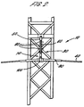
- Figure 2 shows, schematically, the region A of Figure 1.
- a close up schematic view of the suspension member 30 of a suspension tower 10 is shown.
- Features common to Figures 1 and 2 are shown with like reference numerals.
- the suspension member 30 comprises a first end 50 bolted or welded to the tower 10.
- An insulating linkage 60 is attached to the first end 50 of the suspension member 30.
- the insulating linkage preferably includes a number of shedded parts 80 which, in addition to increasing the surface area, also allow any rain or moisture to run off the insulator more easily.
- the end of the insulating linkage 60 distal from the first end 50 of the suspension member 30 carries a preformed suspension fitting 70 for supporting the ADSS cable 40 from the tower 10.
- the preformed tension fitting 70 typically includes relatively thick preformed metal wires 90.
- the preformed wires 90 are threaded through or otherwise attached to a lower end 100 of the insulating linkage 70 and then wrapped around the ADSS optical cable 40.
- the preformed wires may be wrapped around the ADSS optical cable 40 over a distance of a metre or more on either side of the insulating linkage in order to provide the necessary support for the cable even in high winds.
- preformed wires 90 forming a part of the preformed tension fitting 70 lie around the surface of the outer jacket of the ADSS optical cable 40, and the fitting is not designed for insertion into the outer jacket thereof.
- a clamp type fitting could be employed instead, of course.
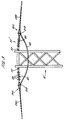
- Figure 3 shows the region B of Figure 1 in close-up. Here, the manner of suspending an ADSS optical cable 40 under tension from a tension tower 10' is shown.
- Features common to Figures 2 and 3 are labelled with like reference numerals.
- a suspension member 30' is employed.
- the suspension member 30' is generally similar to the suspension member 30 of Figure 2, though with some modifications.
- a first end 50 of the suspension member 30' is bolted or otherwise affixed to the tension tower 10'.
- Attached to the first end 50 is an insulating linkage 60 which is preferably similar to the insulating linkage 60 of Figure 2.
- the insulating linkage of Figure 3 includes a plurality of sheds 80 to allow water to run off the linkage 60 more readily.
- the insulating linkage is coated with silicone or another hydrophobic, non-tracking, heat resistant, ablative, material.
- the tension member 200 includes a clevis 210 which is held by the insulating linkage 60, and a preformed helical wire 220.
- the helical wire 220 is wrapped around the jacket of the ADSS optical cable 40 and grips it firmly.
- the cable 40 is held under tension relative to the tension tower 10' by attaching the preformed tension member 200 and pulling it towards the tension tower 10'. Once the cable 40 is correctly located, the helical wire 220 of the tension member 200 is secured to the clevis 210.
- section of the ADSS optical cable 40 not under tension is also not grounded and that special provision may be needed in the Safety Rules to ensure that this section of cable is not allowed to become hazardous.
- a tension member 200 holds the ADSS optical cable 40 under tension, and is attached to the tower itself via an insulating linkage 60 exactly as with the arrangement of Figure 3 described above. This part of the device will not be described in further detail, therefore.
- the cable passes underground, or may be spliced to an underground cable; in the case of a splice tower, the first cable is spliced to a second adjacent cable whose arrangement at the tower mirrors that of the first.
- the insulating linkage 60 of Figures 2, 3 or 4 preferably has two interrelated properties. Firstly, it has a surface that is heat resistant, partially or fully resistant to electrical tracking and which minimises leakage currents, for example by having a surface that is hydrophobic. Therefore, any dry band arcing which does occur on the linkage 60 has insufficient energy to damage it.
- the ADSS dielectric cable 40 also has a track resistant jacket and so likewise any arc currents on its surface do not cause damage.
- the degree of track resistance needed for both the insulator 60 and the ADSS jacket depends upon the leakage current limiting capability of the insulator.
- the insulating linkage is either partially or fully resistant to electrical tracking and has a hydrophobic surface (which therefore tends to limit surface leakage currents). This property causes the insulting linkage 60 to dry out more quickly than the ADSS optical cable 40, so that any dry band arcing preferentially occurs on the insulating linkage 60 rather than the ADSS optical cable 40.
- silicone is particularly suitable for forming the surface of the insulating linkage 60. Not only is silicone non-tracking (i.e., fully resistant to electrical tracking), it is also extremely hydrophobic.
- Silicone has further advantageous properties which make it suitable for use as an insulating linkage 60. Firstly, it is highly temperature resistant. This means that any dry band arcing that occurs on the insulating linkage 60 will be readily withstood, up to a current well above that which the ADSS cable could stand. Secondly, silicone can be ablative - that is, if an arc occurs, the surface of the silicone is renewed by being stripped or ablated of a very fine surface layer to leave a clean, (i.e., hydroscopic) non-tracking surface.
- the type MIP-16-7 insulator manufactured by Raychem Corporation, is suitable for the present application. This is an insulator having a silicone sheath, and is able to reduce the leakage current to around 0.1mA, well below the level at which the ADSS cable 40 (or the linkage 60) might be damaged. Alternatively, the Robosio E00697 type A insulator may be used.
- a test arrangement comprising a length of dielectric cable, an insulating linkage and a sleeve was placed inside a salt-fog chamber.
- the components were arranged to simulate a short span i.e. the dielectric cable was suspended between fixed supports held at ground potential. At one end, the support included the insulating linkage; at the other end the cable was fitted with the sleeve.
- the centre point of the short span was connected to a high voltage source via a wire. Therefore leakage currents flowed in opposite directions along the cable from the centre point. Each leakage current was monitored.
- a salt-fog was applied to the arrangement inside the salt-fog chamber over a fixed period of time, to allow the dielectric cable, sleeve and insulating linkage to become as wet as possible. Use of the salt-fog was then halted.
- leakage currents were measured over three such cycles.
- the results of leakage current measurement on the insulating linkage side are shown in Figure 5a.
- Similar results for leakage current measured on the sleeve side are shown in Figure 5b. It will be seen that in each case, the leakage current during application of the salt-fog averaged substantially less than 1mA, much less than would cause damage during dry band arcing. A peak occurs at the start of the so-called "rain phase" at the end of each cycle.
- Figures 6a and 6b show the results of identical measurements to those described in connection with Figures 5a and 5b, but with the insulating linkage shorted out using a suitable conductor. It will be seen that the peak and average leakage currents on the insulating linkage side are much higher - around 30mA. Likewise, in Figure 6b, which shows the results of measurement of leakage current on the sleeve side, the leakage currents are typically 10mA rising to a peak of over 40mA in one case.
- the level OL the leakage current is a significant factor in the amount of damage caused by dry band arcing; indeed it is apparent that there is a "threshold current" below which dry band arcing has no significant deleterious effect.
- dry band arcing is most unlikely to remain in a single place on a dielectric cable and real weather situations are unlikely as a rule to create the conditions where dry band arcing can occur at all for such prolonged periods.
- the linkage 60 need not have all of the desirable properties outlined above in order to provide significant advantages over the prior art.
- the use of an insulator 60 which limits the maximum leakage current to a very low value means that the high temperature and track resistant properties of insulator 60 and the jacket of the ADSS optical cable 40 are less critical.
- FIG 8a two of a series of towers 10 for carrying high tension power lines 20 are shown. As with Figure 1, only one of the high tension power lines 20 is shown for clarity. As will be understood by the skilled person, the power line 20 is suspended from each tower 10 by insulating power line supports (not shown).
- a pulley block arrangement 410 is first fitted. This arrangement is shown in more detail in Figure 8b and consists of a conventional pulley block adapted to support, on each side, a sleeving installation assembly 415. As may be seen in Figure 8b, the sleeving installation assembly 415 is attached to the pulley block by a clamp 425.
- the sleeving installation assembly 415 is itself shown in close up side view in Figure 9 and in cross section in Figure 10.
- the installation assembly 415 comprises a sleeve 420 supported upon a hollow cylindrical mandrel 440.
- the sleeve 420 is preferably of the elastomeric non-heat shrink form which will be familiar to those skilled in the art.
- Such a sleeve is made of silicone, which is hydrophobic.
- the sleeve is formed with a number of sheds 430 ( Figure 9) which allow rain and atmospheric moisture to run off the sleeve 420.
- the outer diameter of the mandrel 440 supports the sleeve 420 in an expanded state.
- the inner diameter of the mandrel is large enough to allow an ADSS optical cable 40, pulling rope and rope/ADSS optical cable coupling to pass through it.
- a pulling rope 450 is drawn over the pulleys.
- the use of a pulling rope which has been pre-installed over the pulleys will be familiar to those skilled in the art.
- the pulling rope is pre-installed over the pulleys whilst at the same time being threaded through the bore of the hollow cylindrical mandrels 440.
- the pulling rope continues to be pulled through successive mandrels 440 at adjacent towers, until the pulling rope 450 has passed along the full span of towers over which the ADSS cable is to be installed.
- a rope take-up drum and tensioner (not shown).
- a first end of the ADSS cable located adjacent to the first tower 10, is attached to the pulling rope.
- the rope is then drawn back along the pulleys, through the installation assemblies 415 and onto the take-up drum, dragging the first end of the ADSS cable 40 with it.
- the first end of the ADSS cable 40 reaches the pulling rope take-up drum, it is connected to a terminator at the ground level.
- the other, second end of the ADSS cable adjacent the first tower is also cut off and attached to a termination point.
- each mandrel 440 is detached from the pulley block onto which it had been mounted.
- the ADSS optical cable is raised from the pulley block and connected to the support member at that point.
- the mandrels 440 are then detached from their associated pulley block by removing them from their respective clamp 425, so that the mandrels are slidable relative to the (now fixed) ADSS cable 40.
- the pulley blocks 410, as well as the clamps 425 are removed from the towers 10.
- Each mandrel 440 is then slid a short distance away from an adjacent ADSS cable support member, and the sleeve 420 on the mandrel 440 is slipped off. Because the sleeve 420 is elastomeric, it covers and grips the ADSS cable 40 at that point.
- Figure 11 shows a side view of the sleeve 420 following installation. It is desirable that the bore of the sleeve is lined with a mastic or other sealant to prevent moisture ingress along the interface between the sleeve and the ADSS optical cable 40.
Landscapes
- Physics & Mathematics (AREA)
- General Physics & Mathematics (AREA)
- Optics & Photonics (AREA)
- Insulated Conductors (AREA)
- Insulators (AREA)
- Inorganic Insulating Materials (AREA)
- Installation Of Indoor Wiring (AREA)
- Cable Accessories (AREA)
Claims (7)
- Procédé de montage d'un câble diélectrique (40) sur une structure de suspension de ligne à haute tension aérienne (10), lequel comprend :la pose d'un manchon (420) autour d'un mandrin (440), le mandrin (440) définissant à travers ledit manchon une ouverture destinée à recevoir le câble diélectrique (40) ;la disposition du mandrin (440) et du manchon (420) de manière fixe par rapport à la structure de support de ligne à haute tension (10) ;l'introduction du câble diélectrique (40) par l'ouverture du mandrin (440) ;le retrait du mandrin (440) du manchon (420) après que le câble diélectrique (40) a été introduit par l'ouverture du mandrin (440) de sorte que le manchon (420) enveloppe le câble diélectrique (40) ; etl'enlèvement du mandrin (440) du câble diélectrique (40) .
- Procédé selon la revendication 1, dans lequel le manchon (420) est fait d'un élastomère hydrofuge de sorte que le fait de retirer le mandrin (440) du manchon (420) conduise à ce que le manchon saisisse de façon élastique le câble diélectrique (40).
- Procédé selon la revendication 1 ou la revendication 2, dans lequel le mandrin (440) et le manchon (420) sont placés juste à côté de la structure de support de ligne à haute tension (10).
- Procédé selon la revendication 3 comprenant, de plus, l'étape suivante :soutien du câble diélectrique (40) depuis la structure de support de ligne à haute tension (10) au moyen d'un élément de support (60) dont une première extrémité est fixée à la structure de support de ligne à haute tension (10) et dont une seconde extrémité est fixée autour de la surface du câble diélectrique (40).
- Procédé selon la revendication 4, dans lequel le manchon (420) enveloppe la seconde extrémité de l'élément de suspension (60) une fois que le mandrin (440) a été retiré du manchon (420).
- Procédé selon l'une quelconque des revendications précédentes, dans lequel l'étape consistant à disposer le mandrin (440) et le manchon (420) de manière fixe par rapport à la structure de support de ligne à haute tension (10) comprend le montage du mandrin gainé (440) sur une moufle (410) et la fixation de la moufle (410) à la structure de support de ligne à haute tension (10).
- Procédé selon la revendication 6 comprenant de plus, avant l'introduction du câble diélectrique (40) par l'ouverture du mandrin (440), les étapes suivantes :passage d'une corde de tirage (450) par l'ouverture du mandrin (440) une fois que celui-ci a été monté de manière fixe par rapport à la structure de support de ligne à haute tension (10) ;attache de la corde de tirage (450) au câble diélectrique (40) à installer ; ettraction de la corde de tirage (450) par l'ouverture du mandrin (440), ce qui, en conséquence, entraíne l'introduction du câble diélectrique (40) attaché à ladite corde de tirage (450) par l'ouverture du mandrin (440).
Applications Claiming Priority (3)
| Application Number | Priority Date | Filing Date | Title |
|---|---|---|---|
| GB9902682A GB2346488B (en) | 1999-02-05 | 1999-02-05 | Protection of dielectric cables |
| GB9902682 | 1999-02-05 | ||
| PCT/GB2000/000337 WO2000046625A1 (fr) | 1999-02-05 | 2000-02-04 | Protection des cables dielectriques |
Publications (2)
| Publication Number | Publication Date |
|---|---|
| EP1151340A1 EP1151340A1 (fr) | 2001-11-07 |
| EP1151340B1 true EP1151340B1 (fr) | 2002-10-02 |
Family
ID=10847248
Family Applications (1)
| Application Number | Title | Priority Date | Filing Date |
|---|---|---|---|
| EP00901789A Expired - Lifetime EP1151340B1 (fr) | 1999-02-05 | 2000-02-04 | Protection des cables dielectriques |
Country Status (10)
| Country | Link |
|---|---|
| EP (1) | EP1151340B1 (fr) |
| AT (1) | ATE225522T1 (fr) |
| AU (1) | AU759308B2 (fr) |
| CA (1) | CA2361749A1 (fr) |
| DE (1) | DE60000536T2 (fr) |
| ES (1) | ES2186622T3 (fr) |
| GB (1) | GB2346488B (fr) |
| PT (1) | PT1151340E (fr) |
| WO (1) | WO2000046625A1 (fr) |
| ZA (1) | ZA200106097B (fr) |
Families Citing this family (4)
| Publication number | Priority date | Publication date | Assignee | Title |
|---|---|---|---|---|
| US10379308B2 (en) * | 2012-03-19 | 2019-08-13 | Brian D. Coate | Apparatus and method for splicing all-dielectric self-supporting fiber optic cable |
| CN103246034B (zh) * | 2013-06-03 | 2014-11-26 | 上海骏越通信技术有限公司 | 一种自承式蝶形皮线光缆架空铺设的锚接安装方法 |
| CN104944217A (zh) * | 2015-06-26 | 2015-09-30 | 浙江特拉建材有限公司 | 一种电线防断装置 |
| CN113541075B (zh) * | 2021-06-23 | 2023-01-20 | 国网江苏省电力有限公司盐城供电分公司 | 一种电缆断点临时保护装置 |
Family Cites Families (7)
| Publication number | Priority date | Publication date | Assignee | Title |
|---|---|---|---|---|
| DE3506883A1 (de) * | 1985-02-27 | 1986-08-28 | Philips Patentverwaltung Gmbh, 2000 Hamburg | Metallfreies, in der nachbarschaft zu elektrischen hochspannungsanlagen verlegtes optisches luftkabel |
| DE3526741A1 (de) * | 1985-07-26 | 1987-02-05 | Pfisterer Elektrotech Karl | Isolierte abspann- oder haengeklemme |
| GB9204047D0 (en) * | 1992-02-26 | 1992-04-08 | Bicc Plc | Overhead optical transmission system |
| GB2279820B (en) * | 1993-07-02 | 1996-12-11 | Pirelli General Plc | Installing aerial cables |
| GB9516095D0 (en) * | 1995-08-05 | 1995-10-04 | Bicc Plc | Method of installing a resistive element on an optical cable |
| GB2330705A (en) * | 1997-10-27 | 1999-04-28 | Pirelli General Plc | Limiting dry band arcing on an all-dielectric self-supporting cable; arc gap devices |
| GB2335086A (en) * | 1998-03-05 | 1999-09-08 | Pirelli General Plc | Sleeve for protecting all-dialectric cable from dry band arcing |
-
1999
- 1999-02-05 GB GB9902682A patent/GB2346488B/en not_active Expired - Fee Related
-
2000
- 2000-02-04 DE DE60000536T patent/DE60000536T2/de not_active Expired - Fee Related
- 2000-02-04 ES ES00901789T patent/ES2186622T3/es not_active Expired - Lifetime
- 2000-02-04 WO PCT/GB2000/000337 patent/WO2000046625A1/fr not_active Ceased
- 2000-02-04 AT AT00901789T patent/ATE225522T1/de not_active IP Right Cessation
- 2000-02-04 CA CA002361749A patent/CA2361749A1/fr not_active Abandoned
- 2000-02-04 EP EP00901789A patent/EP1151340B1/fr not_active Expired - Lifetime
- 2000-02-04 PT PT00901789T patent/PT1151340E/pt unknown
- 2000-02-04 AU AU23086/00A patent/AU759308B2/en not_active Ceased
-
2001
- 2001-07-25 ZA ZA200106097A patent/ZA200106097B/en unknown
Also Published As
| Publication number | Publication date |
|---|---|
| ATE225522T1 (de) | 2002-10-15 |
| DE60000536D1 (de) | 2002-11-07 |
| GB2346488B (en) | 2001-09-12 |
| GB9902682D0 (en) | 1999-03-31 |
| AU759308B2 (en) | 2003-04-10 |
| DE60000536T2 (de) | 2003-06-18 |
| ZA200106097B (en) | 2002-02-27 |
| CA2361749A1 (fr) | 2000-08-10 |
| EP1151340A1 (fr) | 2001-11-07 |
| PT1151340E (pt) | 2003-02-28 |
| GB2346488A (en) | 2000-08-09 |
| ES2186622T3 (es) | 2003-05-16 |
| WO2000046625A1 (fr) | 2000-08-10 |
| AU2308600A (en) | 2000-08-25 |
Similar Documents
| Publication | Publication Date | Title |
|---|---|---|
| US4772090A (en) | Fiber optic cable arrangements | |
| US5687271A (en) | Shielded fiber optics cable for compatibility with high voltage power lines | |
| US12253730B2 (en) | System for guiding a dielectric cable from phase-to-ground potential | |
| AU662423B2 (en) | Overhead optical transmission system | |
| EP1151340B1 (fr) | Protection des cables dielectriques | |
| RU2141681C1 (ru) | Полупроводящий линейный элемент (варианты) | |
| EP0303740A1 (fr) | Assemblée comprenant un conductor haute tension et un câble à fibres optiques | |
| Rowland et al. | Implementation of a solution to the problem of dry-band arcing on ADSS cables | |
| RU2276416C1 (ru) | Оптический кабель связи | |
| GB2256284A (en) | Voltage stress protection device for dielectric cable | |
| KR20010036083A (ko) | 비전도 자기지지형 광 케이블의 트랙킹 방지장치 | |
| EP0909401A1 (fr) | Raccordement optique sur ligne ht | |
| GB2169099A (en) | Fibre optic cable for use at high voltage | |
| NZ216819A (en) | Optical fibre cable: electric stress relief where fibre leaves h.v. field | |
| WO1995022777A1 (fr) | Raccordement d'un conducteur |
Legal Events
| Date | Code | Title | Description |
|---|---|---|---|
| PUAI | Public reference made under article 153(3) epc to a published international application that has entered the european phase |
Free format text: ORIGINAL CODE: 0009012 |
|
| 17P | Request for examination filed |
Effective date: 20010718 |
|
| AK | Designated contracting states |
Kind code of ref document: A1 Designated state(s): AT BE CH CY DE DK ES FI FR GB GR IE IT LI LU MC NL PT SE |
|
| GRAG | Despatch of communication of intention to grant |
Free format text: ORIGINAL CODE: EPIDOS AGRA |
|
| 17Q | First examination report despatched |
Effective date: 20020128 |
|
| GRAG | Despatch of communication of intention to grant |
Free format text: ORIGINAL CODE: EPIDOS AGRA |
|
| GRAH | Despatch of communication of intention to grant a patent |
Free format text: ORIGINAL CODE: EPIDOS IGRA |
|
| GRAH | Despatch of communication of intention to grant a patent |
Free format text: ORIGINAL CODE: EPIDOS IGRA |
|
| GRAA | (expected) grant |
Free format text: ORIGINAL CODE: 0009210 |
|
| RAP1 | Party data changed (applicant data changed or rights of an application transferred) |
Owner name: COOKSON PROJECTS LIMITED |
|
| AK | Designated contracting states |
Kind code of ref document: B1 Designated state(s): AT BE CH CY DE DK ES FI FR GR IE IT LI LU MC NL PT SE |
|
| PG25 | Lapsed in a contracting state [announced via postgrant information from national office to epo] |
Ref country code: NL Free format text: LAPSE BECAUSE OF FAILURE TO SUBMIT A TRANSLATION OF THE DESCRIPTION OR TO PAY THE FEE WITHIN THE PRESCRIBED TIME-LIMIT Effective date: 20021002 Ref country code: GR Free format text: LAPSE BECAUSE OF FAILURE TO SUBMIT A TRANSLATION OF THE DESCRIPTION OR TO PAY THE FEE WITHIN THE PRESCRIBED TIME-LIMIT Effective date: 20021002 Ref country code: FI Free format text: LAPSE BECAUSE OF FAILURE TO SUBMIT A TRANSLATION OF THE DESCRIPTION OR TO PAY THE FEE WITHIN THE PRESCRIBED TIME-LIMIT Effective date: 20021002 |
|
| REF | Corresponds to: |
Ref document number: 225522 Country of ref document: AT Date of ref document: 20021015 Kind code of ref document: T |
|
| REG | Reference to a national code |
Ref country code: CH Ref legal event code: EP |
|
| REG | Reference to a national code |
Ref country code: IE Ref legal event code: FG4D |
|
| REF | Corresponds to: |
Ref document number: 60000536 Country of ref document: DE Date of ref document: 20021107 |
|
| RAP2 | Party data changed (patent owner data changed or rights of a patent transferred) |
Owner name: ALCOA FUJIKURA LTD. |
|
| PG25 | Lapsed in a contracting state [announced via postgrant information from national office to epo] |
Ref country code: DK Free format text: LAPSE BECAUSE OF FAILURE TO SUBMIT A TRANSLATION OF THE DESCRIPTION OR TO PAY THE FEE WITHIN THE PRESCRIBED TIME-LIMIT Effective date: 20030102 |
|
| PGFP | Annual fee paid to national office [announced via postgrant information from national office to epo] |
Ref country code: AT Payment date: 20030107 Year of fee payment: 4 |
|
| REG | Reference to a national code |
Ref country code: CH Ref legal event code: NV Representative=s name: E. BLUM & CO. PATENTANWAELTE |
|
| PGFP | Annual fee paid to national office [announced via postgrant information from national office to epo] |
Ref country code: IE Payment date: 20030120 Year of fee payment: 4 |
|
| PGFP | Annual fee paid to national office [announced via postgrant information from national office to epo] |
Ref country code: FR Payment date: 20030123 Year of fee payment: 4 |
|
| PGFP | Annual fee paid to national office [announced via postgrant information from national office to epo] |
Ref country code: PT Payment date: 20030129 Year of fee payment: 4 |
|
| PGFP | Annual fee paid to national office [announced via postgrant information from national office to epo] |
Ref country code: SE Payment date: 20030131 Year of fee payment: 4 |
|
| NLT2 | Nl: modifications (of names), taken from the european patent patent bulletin |
Owner name: ALCOA FUJIKURA LTD. |
|
| PG25 | Lapsed in a contracting state [announced via postgrant information from national office to epo] |
Ref country code: LU Free format text: LAPSE BECAUSE OF NON-PAYMENT OF DUE FEES Effective date: 20030204 Ref country code: CY Free format text: LAPSE BECAUSE OF FAILURE TO SUBMIT A TRANSLATION OF THE DESCRIPTION OR TO PAY THE FEE WITHIN THE PRESCRIBED TIME-LIMIT Effective date: 20030204 |
|
| PGFP | Annual fee paid to national office [announced via postgrant information from national office to epo] |
Ref country code: BE Payment date: 20030204 Year of fee payment: 4 |
|
| PGFP | Annual fee paid to national office [announced via postgrant information from national office to epo] |
Ref country code: ES Payment date: 20030217 Year of fee payment: 4 |
|
| PG25 | Lapsed in a contracting state [announced via postgrant information from national office to epo] |
Ref country code: MC Free format text: LAPSE BECAUSE OF NON-PAYMENT OF DUE FEES Effective date: 20030228 |
|
| PGFP | Annual fee paid to national office [announced via postgrant information from national office to epo] |
Ref country code: DE Payment date: 20030228 Year of fee payment: 4 |
|
| REG | Reference to a national code |
Ref country code: PT Ref legal event code: SC4A Free format text: AVAILABILITY OF NATIONAL TRANSLATION Effective date: 20021223 |
|
| NLV1 | Nl: lapsed or annulled due to failure to fulfill the requirements of art. 29p and 29m of the patents act | ||
| ET | Fr: translation filed | ||
| REG | Reference to a national code |
Ref country code: ES Ref legal event code: FG2A Ref document number: 2186622 Country of ref document: ES Kind code of ref document: T3 |
|
| PLBE | No opposition filed within time limit |
Free format text: ORIGINAL CODE: 0009261 |
|
| STAA | Information on the status of an ep patent application or granted ep patent |
Free format text: STATUS: NO OPPOSITION FILED WITHIN TIME LIMIT |
|
| 26N | No opposition filed |
Effective date: 20030703 |
|
| PG25 | Lapsed in a contracting state [announced via postgrant information from national office to epo] |
Ref country code: IE Free format text: LAPSE BECAUSE OF NON-PAYMENT OF DUE FEES Effective date: 20040204 Ref country code: AT Free format text: LAPSE BECAUSE OF NON-PAYMENT OF DUE FEES Effective date: 20040204 |
|
| PG25 | Lapsed in a contracting state [announced via postgrant information from national office to epo] |
Ref country code: SE Free format text: LAPSE BECAUSE OF NON-PAYMENT OF DUE FEES Effective date: 20040205 Ref country code: ES Free format text: LAPSE BECAUSE OF NON-PAYMENT OF DUE FEES Effective date: 20040205 |
|
| PG25 | Lapsed in a contracting state [announced via postgrant information from national office to epo] |
Ref country code: BE Free format text: LAPSE BECAUSE OF NON-PAYMENT OF DUE FEES Effective date: 20040228 |
|
| PG25 | Lapsed in a contracting state [announced via postgrant information from national office to epo] |
Ref country code: LI Free format text: LAPSE BECAUSE OF NON-PAYMENT OF DUE FEES Effective date: 20040229 Ref country code: CH Free format text: LAPSE BECAUSE OF NON-PAYMENT OF DUE FEES Effective date: 20040229 |
|
| BERE | Be: lapsed |
Owner name: *ALCOA FUJIKURA LTD Effective date: 20040228 |
|
| PG25 | Lapsed in a contracting state [announced via postgrant information from national office to epo] |
Ref country code: PT Free format text: LAPSE BECAUSE OF NON-PAYMENT OF DUE FEES Effective date: 20040831 |
|
| PG25 | Lapsed in a contracting state [announced via postgrant information from national office to epo] |
Ref country code: DE Free format text: LAPSE BECAUSE OF NON-PAYMENT OF DUE FEES Effective date: 20040901 |
|
| EUG | Se: european patent has lapsed | ||
| REG | Reference to a national code |
Ref country code: CH Ref legal event code: PL |
|
| PG25 | Lapsed in a contracting state [announced via postgrant information from national office to epo] |
Ref country code: FR Free format text: LAPSE BECAUSE OF NON-PAYMENT OF DUE FEES Effective date: 20041029 |
|
| REG | Reference to a national code |
Ref country code: IE Ref legal event code: MM4A |
|
| REG | Reference to a national code |
Ref country code: FR Ref legal event code: ST |
|
| PG25 | Lapsed in a contracting state [announced via postgrant information from national office to epo] |
Ref country code: IT Free format text: LAPSE BECAUSE OF NON-PAYMENT OF DUE FEES Effective date: 20050204 |
|
| REG | Reference to a national code |
Ref country code: ES Ref legal event code: FD2A Effective date: 20040205 |