EP1151781A2 - Trennwandkolonne - Google Patents
Trennwandkolonne Download PDFInfo
- Publication number
- EP1151781A2 EP1151781A2 EP01110116A EP01110116A EP1151781A2 EP 1151781 A2 EP1151781 A2 EP 1151781A2 EP 01110116 A EP01110116 A EP 01110116A EP 01110116 A EP01110116 A EP 01110116A EP 1151781 A2 EP1151781 A2 EP 1151781A2
- Authority
- EP
- European Patent Office
- Prior art keywords
- dividing wall
- column
- partition
- wall
- trennwand
- Prior art date
- Legal status (The legal status is an assumption and is not a legal conclusion. Google has not performed a legal analysis and makes no representation as to the accuracy of the status listed.)
- Granted
Links
- 238000005192 partition Methods 0.000 claims abstract description 68
- 239000013013 elastic material Substances 0.000 claims abstract description 9
- 239000000463 material Substances 0.000 claims abstract description 5
- 238000004519 manufacturing process Methods 0.000 claims description 10
- 239000007769 metal material Substances 0.000 claims description 5
- 239000004033 plastic Substances 0.000 claims description 5
- 229910001220 stainless steel Inorganic materials 0.000 claims description 3
- 238000005260 corrosion Methods 0.000 claims description 2
- 230000007797 corrosion Effects 0.000 claims description 2
- -1 polytetrafluoroethylene Polymers 0.000 claims description 2
- 229920001343 polytetrafluoroethylene Polymers 0.000 claims description 2
- 239000004810 polytetrafluoroethylene Substances 0.000 claims description 2
- 239000010935 stainless steel Substances 0.000 claims description 2
- VNNRSPGTAMTISX-UHFFFAOYSA-N chromium nickel Chemical compound [Cr].[Ni] VNNRSPGTAMTISX-UHFFFAOYSA-N 0.000 claims 1
- 238000004821 distillation Methods 0.000 description 9
- 239000000203 mixture Substances 0.000 description 6
- 239000006227 byproduct Substances 0.000 description 4
- 238000009835 boiling Methods 0.000 description 3
- 239000007788 liquid Substances 0.000 description 3
- 238000012856 packing Methods 0.000 description 3
- PXHVJJICTQNCMI-UHFFFAOYSA-N Nickel Chemical compound [Ni] PXHVJJICTQNCMI-UHFFFAOYSA-N 0.000 description 2
- 238000010276 construction Methods 0.000 description 2
- 239000011521 glass Substances 0.000 description 2
- 239000000047 product Substances 0.000 description 2
- 238000007789 sealing Methods 0.000 description 2
- 239000000126 substance Substances 0.000 description 2
- VYZAMTAEIAYCRO-UHFFFAOYSA-N Chromium Chemical compound [Cr] VYZAMTAEIAYCRO-UHFFFAOYSA-N 0.000 description 1
- 230000002411 adverse Effects 0.000 description 1
- 239000000919 ceramic Substances 0.000 description 1
- 229910052804 chromium Inorganic materials 0.000 description 1
- 239000011651 chromium Substances 0.000 description 1
- 238000005265 energy consumption Methods 0.000 description 1
- 238000000605 extraction Methods 0.000 description 1
- 239000012530 fluid Substances 0.000 description 1
- 238000002955 isolation Methods 0.000 description 1
- 229910052751 metal Inorganic materials 0.000 description 1
- 239000002184 metal Substances 0.000 description 1
- 238000002156 mixing Methods 0.000 description 1
- 229910052759 nickel Inorganic materials 0.000 description 1
- 230000002441 reversible effect Effects 0.000 description 1
- 238000000926 separation method Methods 0.000 description 1
- 239000002689 soil Substances 0.000 description 1
Images


Classifications
-
- B—PERFORMING OPERATIONS; TRANSPORTING
- B01—PHYSICAL OR CHEMICAL PROCESSES OR APPARATUS IN GENERAL
- B01D—SEPARATION
- B01D3/00—Distillation or related exchange processes in which liquids are contacted with gaseous media, e.g. stripping
- B01D3/14—Fractional distillation or use of a fractionation or rectification column
- B01D3/141—Fractional distillation or use of a fractionation or rectification column where at least one distillation column contains at least one dividing wall
-
- B—PERFORMING OPERATIONS; TRANSPORTING
- B01—PHYSICAL OR CHEMICAL PROCESSES OR APPARATUS IN GENERAL
- B01D—SEPARATION
- B01D3/00—Distillation or related exchange processes in which liquids are contacted with gaseous media, e.g. stripping
- B01D3/14—Fractional distillation or use of a fractionation or rectification column
- B01D3/143—Fractional distillation or use of a fractionation or rectification column by two or more of a fractionation, separation or rectification step
- B01D3/146—Multiple effect distillation
Definitions
- Partition wall columns and thermally coupled columns offer compared to the Arrangement of conventional distillation columns both in terms of Energy requirements as well as the investment costs are advantages and therefore preferably used industrially.
- Thermally used for distillation purposes coupled distillation columns or dividing wall columns are usually as Packing columns or packing columns containing ordered packings or as Soil columns designed.
- the above-mentioned manufacturing methods are especially for the construction smaller dividing wall columns are complex and are particularly not suitable for the construction of dividing wall columns with a diameter of less than 0.2 m exhibit. These manufacturing methods are therefore particularly suitable for laboratory, Technical and smaller production columns are time and cost-intensive or not suitable.
- the invention has for its object a dividing wall column to provide, the partition is easily and effectively attached.
- the Corresponding fastening mechanism is intended in particular in the manufacture of small dividing wall columns may be advantageous.
- the partition the partition is at least partially formed from an elastic material has a slight excess in terms of its width and the attachment of the Partition in the column takes place in that the partition on the Inner shell of the column exerts an elastic restoring force.
- elastic material should be understood to mean that it is reversible is deformable. Glass or, for example, is said to be a non-elastic material Ceramics can be understood. With elastic material, after deformation of the body made of the elastic material in the body a Restoring force that persists until the body returns to its original shape (until the deformation is removed).
- partition has a slight excess in terms of its width is said in usually mean that the partition is slightly wider than the inside diameter the column (this applies to symmetrical, cylindrical columns - Normal case). As a slight excess, up to a maximum of 5% of the length of the Column inner diameter can be understood. The slight excess of Partition ultimately causes the partition to compress, which is reflected in usually noticeable in a slight curvature of the partition.
- the partition is fastened in the column in that the Partition on the inner jacket of the column an elastic restoring force exercises.
- the suitable fits are made according to the usual design principles determined and result from the design of the partition, its rigidity and the manufacturing tolerance of the column inner jacket.
- the advantage of the dividing wall column according to the invention is that it is simple and can be produced inexpensively - the partition is easy to install and remove.
- the partition can be divided into small columns such as laboratory or Technical center columns, easy to install. Because the partition is also simply made the column is removable, the column can be easily converted.
- the partition is usually made entirely of an elastic material.
- the partition is usually available as a band made in one piece.
- the material from which the partition is made often contains plastic, for example polytetrafluoroethylene.
- the partition can also be made completely Plastic.
- the material from which the partition is formed often has corrosion-resistant metallic materials such as chromium / nickel-containing Stainless steels, on.
- the partition can be made entirely of metallic materials consist.
- the side edges of the partition are often chamfered, with the Chamfer angle is preferably 20 to 60 °. Is usually particularly preferred a chamfer angle of 30 to 45 °.
- the partition is usually straight or curved in a Z or U shape Column in front. If the partition is bent in a Z or U shape, the Partition in its central area essentially straight (or only slightly arched), with only the edges that lie on the inner jacket of the column, are shaped accordingly.
- a Z or U-shaped bend in the Partition wall can tolerate larger roundness of the column inner shell be, because of the Z- or U-shape of the partition a higher Tightness is guaranteed.
- the manufacturing tolerance of the inner diameter of the column is usually ⁇ 1.5 mm, preferably ⁇ 1 mm.
- the partition is often made entirely of a metallic material formed and the wall thickness of the partition is 0.05 to 1 mm, preferably 0.1 to 0.3 mm.
- the partition can be made entirely of plastic be formed and the wall thickness of the partition is then usually 1 to 10 mm, preferably 2 to 5 mm.
- the thickness of the partition depends on Principle according to that the partition is sufficiently firm and stiff, but still is flexible.
- the partition is usually up to 3 m long the column is pulled - the dividing wall is in the column shot or in several column shots retracted one above the other.
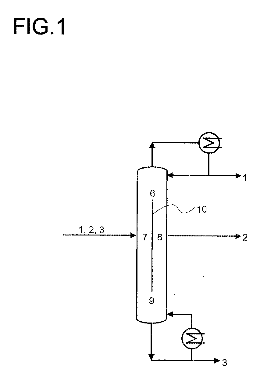
- FIG. 1 and 2 show schematically, as in a dividing wall column a starting mixture consisting of low boilers 1, medium boilers 2 and high boilers 3 is separated.
- Middle boiler 2 from two components 4; 5.
- the dividing wall column are as Segments an upper column area 6, an inlet part 7, a removal part 8 and one included under column area 9.
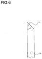
- the column is in the middle by the Partition 10 divided. 6 is the chamfered edge of a partition shown schematically, the chamfer 11 is shown.
Landscapes
- Chemical & Material Sciences (AREA)
- Chemical Kinetics & Catalysis (AREA)
- Vaporization, Distillation, Condensation, Sublimation, And Cold Traps (AREA)
- Organic Low-Molecular-Weight Compounds And Preparation Thereof (AREA)
- Structures Of Non-Positive Displacement Pumps (AREA)
- Rotary Pumps (AREA)
- Recrystallisation Techniques (AREA)
- Treatment Of Liquids With Adsorbents In General (AREA)
- Acyclic And Carbocyclic Compounds In Medicinal Compositions (AREA)
- Physical Or Chemical Processes And Apparatus (AREA)
Abstract
Description
- einen oberen Kolonnenbereich, der sich oberhalb der Trennwand befindet,
- einen Zulaufteil, der sich auf der Seite der Zulaufstelle befindet und seitlich durch eine Trennwand abgetrennt wird,
- einen Entnahmeteil, der sich auf der Seite der Seitenabzugsstelle befindet und seitlich durch die Trennwand abgegrenzt wird und
- einen unteren Kolonnenbereich, der sich unterhalb der Trennwand befindet.
- in Fig. 1 und Fig. 2
- Schemata von Trennwandkolonnen,
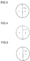
- in Fig. 3
- eine in die Kolonne eingebaute, gerade Trennwand,
- in Fig. 4
- eine in die Kolonne eingebaute, U-förmig gebogene Trennwand,
- in Fig. 5
- eine in die Kolonne eingebaute, Z-förmig gebogene Trennwand und
- in Fig. 6
- einen angefasten Rand einer Trennwand.
Claims (10)
- Trennwandkolonne aufweisend als Segmente,a) einen oberen Kolonnenbereich (6),b) einen Zulaufteil (7),c) einen Entnahmeteil (8) undd) einen unteren Kolonnenbereich (9),
wobei der Zulaufteil b) (7) und der Entnahmeteil c) (8) durch eine in der Kolonne befestigte Trennwand (10) seitlich voneinander abgetrennt sind und die Trennwand (10) zwischen dem oberen Kolonnenbereich a) (6) und dem unteren Kolonnenbereich d) (9) angeordnet ist, dadurch gekennzeichnet, daß die Trennwand (10) zumindest teilweise aus einem elastischen Material ausgebildet ist, die Trennwand (10) bezüglich ihrer Breite ein geringes Übermaß aufweist und die Befestigung der Trennwand (10) in der Kolonne dadurch erfolgt, daß die Trennwand auf den Innenmantel der Kolonne eine elastische Rückstellkraft ausübt. - Trennwandkolonne nach Anspruch 1, dadurch gekennzeichnet, daß die Trennwand (10) vollständig aus einem elastischen Material ausgebildet ist.
- Trennwandkolonne nach Anspruch 1 oder 2, dadurch gekennzeichnet, daß die Trennwand (10) als ein in einem Stück gefertigtes Band vorliegt.
- Trennwandkolonne nach einem der Ansprüche 1 bis 3, dadurch gekennzeichnet, daß das Material, aus dem die Trennwand (10) ausgebildet ist, Kunststoff, bevorzugt Polytetrafluorethylen, enthält.
- Trennwandkolonne nach einem der Ansprüche 1 bis 4, dadurch gekennzeichnet, daß das Material, aus dem die Trennwand (10) ausgebildet ist, korrosionsbeständige metallische Werkstoffe, bevorzugt chrom-nickelhaltige Edelstähle, aufweist.
- Trennwandkolonne nach einem der Ansprüche 1 bis 5, dadurch gekennzeichnet, daß die seitlichen Ränder der Trennwand (10) angefaßt sind, wobei der Anfaswinkel (11) bevorzugt 20 bis 60° beträgt.
- Trennwandkolonne nach einem der Ansprüche 1 bis 6, dadurch gekennzeichnet, daß die Trennwand (10) gerade oder Z- oder U-förmig gebogen in der Kolonne angeordnet ist.
- Trennwandkolonne nach einem der Ansprüche 1 bis 7, dadurch gekennzeichnet, daß die Fertigungstoleranz des Innendurchmessers der Kolonne kleiner 1,5 mm, bevorzugt kleiner 1 mm, ist.
- Trennwandkolonne nach einem der Ansprüche 1 bis 8, dadurch gekennzeichnet, daß die Trennwand (10) vollständig aus einem metallischen Werkstoff ausgebildet ist und die Wandstärke der Trennwand (10) 0,05 bis 1 mm, bevorzugt 0,1 bis 0,3 mm, beträgt.
- Trennwandkolonne nach einem der Ansprüche 1 bis 8, dadurch gekennzeichnet, daß die Trennwand (10) vollständig aus Kunststoff ausgebildet ist und die Wandstärke der Trennwand (10) 1 bis 10 mm, bevorzugt 2 bis 5 mm, beträgt.
Applications Claiming Priority (2)
| Application Number | Priority Date | Filing Date | Title |
|---|---|---|---|
| DE10021624 | 2000-05-04 | ||
| DE10021624A DE10021624A1 (de) | 2000-05-04 | 2000-05-04 | Trennwandkolonne |
Publications (3)
| Publication Number | Publication Date |
|---|---|
| EP1151781A2 true EP1151781A2 (de) | 2001-11-07 |
| EP1151781A3 EP1151781A3 (de) | 2002-06-19 |
| EP1151781B1 EP1151781B1 (de) | 2006-07-26 |
Family
ID=7640700
Family Applications (1)
| Application Number | Title | Priority Date | Filing Date |
|---|---|---|---|
| EP01110116A Expired - Lifetime EP1151781B1 (de) | 2000-05-04 | 2001-05-03 | Trennwandkolonne |
Country Status (4)
| Country | Link |
|---|---|
| US (1) | US6958111B2 (de) |
| EP (1) | EP1151781B1 (de) |
| AT (1) | ATE333927T1 (de) |
| DE (2) | DE10021624A1 (de) |
Cited By (4)
| Publication number | Priority date | Publication date | Assignee | Title |
|---|---|---|---|---|
| WO2004009204A1 (de) * | 2002-07-23 | 2004-01-29 | Basf Aktiengesellschaft | Verfahren zur kontinuierlich betriebenen reindestillation von oxiranen, speziell von propylenoxid |
| EP1514955A1 (de) * | 2003-09-04 | 2005-03-16 | BASF Aktiengesellschaft | Verfahren zur destillativen Aufarbeitung eines Tmof enthaltenden Elektrolyseaustrages |
| CN103830926A (zh) * | 2014-03-05 | 2014-06-04 | 宣城亨泰化工科技有限公司 | 电子级氢氟酸生产用精馏塔 |
| DE102018006707A1 (de) * | 2018-08-24 | 2020-02-27 | Julius Montz Gmbh | Kolonne mit Trennwand |
Families Citing this family (48)
| Publication number | Priority date | Publication date | Assignee | Title |
|---|---|---|---|---|
| DE10233388A1 (de) * | 2002-07-23 | 2004-02-12 | Basf Ag | Verfahren zur kontinuierlich betriebenen Reindestillation des bei der koppel-produktfreien Propylenoxidsynthese verwendeten Lösungsmittels Methanol unter gleichzeitiger Abtrennung der Methoxypropanole und der Schwersieder |
| DE10233383A1 (de) * | 2002-07-23 | 2004-02-12 | Basf Ag | Verfahren zur kontinuierlich betriebenen Zwischenabtrennung des bei der koppelproduktfreien Oxiransynthese entstehenden Oxirans unter Verwendung einer Trennwandkolonne |
| DE10233386A1 (de) * | 2002-07-23 | 2004-02-12 | Basf Ag | Verfahren zur kontinuierlich betriebenen Reindestillation des bei der koppel-produktfreien Propylenoxidsynthese verwendeten Lösungsmittels Methanol unter gleichzeitiger Abtrennung der Methoxypropanole |
| US7357378B2 (en) * | 2004-10-18 | 2008-04-15 | Air Prodcuts And Chemicals, Inc. | Divided wall exchange column |
| DE102006000995A1 (de) * | 2006-01-05 | 2007-07-12 | Basf Ag | Verfahren zur kontinuierlichen Herstellung eines primären aromatischen Amins |
| AU2007345353B2 (en) * | 2007-01-19 | 2013-02-21 | Exxonmobil Upstream Research Company | Integrated controlled freeze zone (CFZ) tower and dividing wall (DWC) for enhanced hydrocarbon recovery |
| US7525003B2 (en) * | 2007-05-23 | 2009-04-28 | Uop Llc | Process for producing ethylbenzene |
| US7525005B2 (en) * | 2007-05-23 | 2009-04-28 | Uop Llc | Process for producing cumene |
| US7498472B2 (en) * | 2007-05-23 | 2009-03-03 | Uop Llc | Process for producing ethylbenzene |
| US7525004B2 (en) * | 2007-05-23 | 2009-04-28 | Uop Llc | Process for producing ethylbenzene |
| US7498471B2 (en) * | 2007-05-23 | 2009-03-03 | Uop Llc | Process for producing cumene |
| US7525006B2 (en) * | 2007-05-23 | 2009-04-28 | Uop Llc | Process for producing cumene |
| EP2161063B1 (de) * | 2008-09-03 | 2016-11-02 | L'Air Liquide Société Anonyme pour l'Etude et l'Exploitation des Procédés Georges Claude | Verfahren zur herstellung einer kolonne mit trennwand |
| EP2331225B1 (de) * | 2008-09-17 | 2014-02-26 | Basf Se | Vorrichtungen und verfahren zur kontinuierlichen destillativen auftrennung eines gemisches enthaltend ein oder mehrere alkanolamin/e |
| US8480860B2 (en) * | 2008-10-22 | 2013-07-09 | Air Products And Chemicals, Inc. | Divided wall columns for smaller sized plants |
| US8323457B2 (en) | 2008-10-30 | 2012-12-04 | Kellogg Brown & Root Llc | Dividing wall column with a heat pump |
| KR101191122B1 (ko) * | 2009-01-20 | 2012-10-15 | 주식회사 엘지화학 | 고순도 노르말 부탄올 생산용 분리벽형 증류탑, 및 노르말 부탄올 증류방법 |
| WO2010107284A2 (ko) * | 2009-03-19 | 2010-09-23 | 주식회사 엘지화학 | 고순도 아크릴산 생산을 위한 분리벽형 증류탑 및 이를 이용한 분별증류방법 |
| CA2663397A1 (en) * | 2009-04-20 | 2010-10-20 | Ian Mcgregor | Stripping absorption module |
| AU2010239718B2 (en) | 2009-04-20 | 2016-02-04 | Exxonmobil Upstream Research Company | Cryogenic system for removing acid gases from a hyrdrocarbon gas stream, and method of removing acid gases |
| EA024440B1 (ru) | 2009-09-09 | 2016-09-30 | Эксонмобил Апстрим Рисерч Компани | Криогенная система для удаления кислотных газов из потока газообразных углеводородов |
| CA2786574C (en) | 2010-01-22 | 2016-06-28 | Exxonmobil Upstream Research Company | Removal of acid gases from a gas stream, with co2 capture and sequestration |
| CN102740941A (zh) | 2010-02-03 | 2012-10-17 | 埃克森美孚上游研究公司 | 使用冷却液从工艺气流中去除可凝固的气体组分的系统和方法 |
| BR112013000263A2 (pt) | 2010-07-30 | 2016-05-24 | Exxonmobil Upstream Res Co | sistemas criogênicos para remover gases ácidos de uma corrente de gás de hidrocarboneto usando dispostivos de separação em co-corrente |
| KR101372617B1 (ko) * | 2011-11-11 | 2014-03-11 | 주식회사 엘지화학 | 트리할로실란의 정제 장치 |
| EP2778131B1 (de) * | 2011-11-11 | 2017-10-11 | LG Chem, Ltd. | Vorrichtung zur veredelung von trihalosilan |
| US9683776B2 (en) | 2012-02-16 | 2017-06-20 | Kellogg Brown & Root Llc | Systems and methods for separating hydrocarbons using one or more dividing wall columns |
| WO2013142100A1 (en) | 2012-03-21 | 2013-09-26 | Exxonmobil Upstream Research Company | Separating carbon dioxide and ethane from a mixed stream |
| US9874395B2 (en) | 2013-12-06 | 2018-01-23 | Exxonmobil Upstream Research Company | Method and system for preventing accumulation of solids in a distillation tower |
| WO2015084498A2 (en) | 2013-12-06 | 2015-06-11 | Exxonmobil Upstream Research Company | Method and system for separating a feed stream with a feed stream distribution mechanism |
| EA031531B1 (ru) | 2013-12-06 | 2019-01-31 | Эксонмобил Апстрим Рисерч Компани | Способ и устройство для разделения углеводородов и загрязняющих примесей с помощью нагревательного устройства для дестабилизации и/или предотвращения адгезии твердых веществ |
| US9562719B2 (en) | 2013-12-06 | 2017-02-07 | Exxonmobil Upstream Research Company | Method of removing solids by modifying a liquid level in a distillation tower |
| MY176633A (en) | 2013-12-06 | 2020-08-19 | Exxonmobil Upstream Res Co | Method and system of modifiying a liquid level during start-up operations |
| MY177751A (en) | 2013-12-06 | 2020-09-23 | Exxonmobil Upstream Res Co | Method and device for separating a feed stream using radiation detectors |
| US9752827B2 (en) | 2013-12-06 | 2017-09-05 | Exxonmobil Upstream Research Company | Method and system of maintaining a liquid level in a distillation tower |
| MX363830B (es) | 2013-12-06 | 2019-04-04 | Exxonmobil Upstream Res Co | Metodo y dispositivo para separar hidrocarburos y contaminantes con un ensamblaje de rocio. |
| US9803918B2 (en) | 2013-12-06 | 2017-10-31 | Exxonmobil Upstream Research Company | Method and system of dehydrating a feed stream processed in a distillation tower |
| EP2952237A1 (de) | 2014-06-02 | 2015-12-09 | Sulzer Chemtech AG | Verfahren zur Reinigung von Benzoesäure |
| CN107208964B (zh) | 2015-02-27 | 2020-06-19 | 埃克森美孚上游研究公司 | 减少进入低温蒸馏过程的进料物流的冷冻和脱水负荷 |
| CA2994812C (en) | 2015-09-18 | 2020-03-10 | Exxonmobil Upstream Research Company | Heating component to reduce solidification in a cryogenic distillation system |
| US11255603B2 (en) | 2015-09-24 | 2022-02-22 | Exxonmobil Upstream Research Company | Treatment plant for hydrocarbon gas having variable contaminant levels |
| EA201892054A1 (ru) | 2016-03-30 | 2019-02-28 | Эксонмобил Апстрим Рисерч Компани | Поступающая из собственных источников пластовая текучая среда для повышения нефтеотдачи |
| TWI643657B (zh) * | 2017-12-29 | 2018-12-11 | 財團法人工業技術研究院 | 廢溶劑處理系統及方法 |
| WO2020005553A1 (en) | 2018-06-29 | 2020-01-02 | Exxonmobil Upstream Research Company (Emhc-N1.4A.607) | Mixing and heat integration of melt tray liquids in a cryogenic distillation tower |
| US11306267B2 (en) | 2018-06-29 | 2022-04-19 | Exxonmobil Upstream Research Company | Hybrid tray for introducing a low CO2 feed stream into a distillation tower |
| CN111643915B (zh) * | 2019-09-10 | 2021-09-10 | 上海浦景化工技术股份有限公司 | 一种用于羰基合成醋酸的精馏装置及精馏方法 |
| WO2023140986A1 (en) | 2022-01-19 | 2023-07-27 | Exxonmobil Chemical Patents Inc. | Compositions containing tri-cyclopentadiene and processes for making same |
| WO2025244981A1 (en) | 2024-05-20 | 2025-11-27 | ExxonMobil Technology and Engineering Company | Processes for making exo-dicyclopentadiene and tricyclopentadiene |
Family Cites Families (12)
| Publication number | Priority date | Publication date | Assignee | Title |
|---|---|---|---|---|
| US2471134A (en) * | 1946-07-17 | 1949-05-24 | Standard Oil Dev Co | Fractionation apparatus |
| US4230533A (en) * | 1978-06-19 | 1980-10-28 | Phillips Petroleum Company | Fractionation method and apparatus |
| DE3302525A1 (de) | 1983-01-26 | 1984-07-26 | Basf Ag, 6700 Ludwigshafen | Destillationskolonne zur destillativen zerlegung eines aus mehreren fraktionen bestehenden zulaufproduktes |
| DE4328424A1 (de) * | 1993-08-24 | 1995-03-02 | Basf Ag | Destillationskolonne zur Trennung eines Flüssigkeitsgemisches in mehrere reine Fraktionen |
| DE4336983C2 (de) | 1993-10-29 | 2001-10-18 | Montz Gmbh Julius | Kolonne mit einer Trennwand |
| DE4336986C2 (de) | 1993-10-29 | 2001-09-13 | Montz Gmbh Julius | Kolonne mit Trennwand |
| US5755933A (en) * | 1995-07-24 | 1998-05-26 | The M. W. Kellogg Company | Partitioned distillation column |
| DE19617210A1 (de) * | 1996-04-30 | 1997-11-06 | Basf Ag | Trennwandkolonne zur kontinuierlichen destillativen Zerlegung von Mehrstoffgemischen |
| DE19914966A1 (de) * | 1999-04-01 | 2000-10-05 | Basf Ag | Verfahren zur kontinuierlich betriebenen destillativen Abtrennung eines höherschmelzenden Stoffes |
| US6558515B1 (en) * | 2001-04-23 | 2003-05-06 | Uop Llc | Dividing wall fractionation column control system and apparatus |
| US6551465B1 (en) * | 2001-04-23 | 2003-04-22 | Uop Llc | Dividing wall column control system |
| US6645350B1 (en) * | 2001-06-15 | 2003-11-11 | Uop Llc | Dividing wall column fractionation tray |
-
2000
- 2000-05-04 DE DE10021624A patent/DE10021624A1/de not_active Withdrawn
-
2001
- 2001-05-03 AT AT01110116T patent/ATE333927T1/de not_active IP Right Cessation
- 2001-05-03 EP EP01110116A patent/EP1151781B1/de not_active Expired - Lifetime
- 2001-05-03 DE DE50110518T patent/DE50110518D1/de not_active Expired - Fee Related
- 2001-05-03 US US09/847,299 patent/US6958111B2/en not_active Expired - Fee Related
Cited By (6)
| Publication number | Priority date | Publication date | Assignee | Title |
|---|---|---|---|---|
| WO2004009204A1 (de) * | 2002-07-23 | 2004-01-29 | Basf Aktiengesellschaft | Verfahren zur kontinuierlich betriebenen reindestillation von oxiranen, speziell von propylenoxid |
| US7550064B2 (en) | 2002-07-23 | 2009-06-23 | Basf Aktiengesellschaft | Method for continuously operated pure distillation of oxiranes, especially propylene oxide |
| EP1514955A1 (de) * | 2003-09-04 | 2005-03-16 | BASF Aktiengesellschaft | Verfahren zur destillativen Aufarbeitung eines Tmof enthaltenden Elektrolyseaustrages |
| CN103830926A (zh) * | 2014-03-05 | 2014-06-04 | 宣城亨泰化工科技有限公司 | 电子级氢氟酸生产用精馏塔 |
| CN103830926B (zh) * | 2014-03-05 | 2015-12-23 | 宣城亨泰电子化学材料有限公司 | 电子级氢氟酸生产用精馏塔 |
| DE102018006707A1 (de) * | 2018-08-24 | 2020-02-27 | Julius Montz Gmbh | Kolonne mit Trennwand |
Also Published As
| Publication number | Publication date |
|---|---|
| EP1151781A3 (de) | 2002-06-19 |
| EP1151781B1 (de) | 2006-07-26 |
| DE10021624A1 (de) | 2001-11-08 |
| DE50110518D1 (de) | 2006-09-07 |
| US6958111B2 (en) | 2005-10-25 |
| US20010052453A1 (en) | 2001-12-20 |
| ATE333927T1 (de) | 2006-08-15 |
Similar Documents
| Publication | Publication Date | Title |
|---|---|---|
| EP1151781B1 (de) | Trennwandkolonne | |
| EP1127601B1 (de) | Trennwandkolonne zur Auftrennung eines Vielstoffgemisches | |
| EP3741443A1 (de) | Filter und filtereinsatz | |
| WO2017108714A1 (de) | Injektor aus silizium für die halbleiterindustrie | |
| DE102017000792B4 (de) | Filterelement, Verfahren zu dessen Herstellung und Luftfilter | |
| EP0096267B1 (de) | Ringförmiger Füllkörper für Gas-Flüssigkeitskontakt | |
| DE3514250C2 (de) | ||
| DE2610584B2 (de) | Selbstarretierender Dichtring | |
| DE10231696A1 (de) | Filtereinsatz mit einer zu einem Faltenbalg gefalteten Filtermatte | |
| DE102022103297B4 (de) | Filterelement und filtervorrichtung | |
| DE102006015718A1 (de) | Verteilersystem und Verfahren zu seiner Herstellung | |
| EP0438676B1 (de) | Vorrichtung zum Abscheiden von Fluiden | |
| DE102024128052A1 (de) | Filterelement und Filtersystem | |
| DE2414581A1 (de) | Brennkammer-baueinheit fuer ein gasturbinentriebwerk | |
| DE2850614C2 (de) | Thermisch beanspruchbares Bauteil nach Art einer Wand oder eines Stegs, insbesondere Zwischenwand in einem mehrflutigen Rohr einer Abgasanlage | |
| DE102016205947A1 (de) | Reinigungsdüse mit gekrümmter Strahlführung für einen Dampf- und/oder Hochdruckreiniger | |
| DE3230280C2 (de) | Zyklon | |
| DE3316839A1 (de) | An einer steigleiter befestigbares schutzgitter | |
| DE10330313A1 (de) | Stoßfänger für ein Kraftfahrzeug | |
| DE2560039B1 (de) | Axial steifes,winkelbewegliches Verbindungsstueck fuer Abgasleitungen von Brennkraftmaschinen | |
| DE102019127773A1 (de) | Filtereinsatz zur Flüssigkeitsabscheidung, insbesondere aus einem Aerosol | |
| DE9013468U1 (de) | Abscheider | |
| DE102024210011A1 (de) | Schaufelblattkonstruktion, wasserabscheider und brennstoffzelle | |
| DE1106127B (de) | Rueckstroemdrossel mit zentralen oder ringfoermigen Widerstandskoerpern | |
| DE3024060A1 (de) | Vorrichtung zur drallabscheidung |
Legal Events
| Date | Code | Title | Description |
|---|---|---|---|
| PUAI | Public reference made under article 153(3) epc to a published international application that has entered the european phase |
Free format text: ORIGINAL CODE: 0009012 |
|
| AK | Designated contracting states |
Kind code of ref document: A2 Designated state(s): AT BE CH CY DE DK ES FI FR GB GR IE IT LI LU MC NL PT SE TR |
|
| AX | Request for extension of the european patent |
Free format text: AL;LT;LV;MK;RO;SI |
|
| PUAL | Search report despatched |
Free format text: ORIGINAL CODE: 0009013 |
|
| AK | Designated contracting states |
Kind code of ref document: A3 Designated state(s): AT BE CH CY DE DK ES FI FR GB GR IE IT LI LU MC NL PT SE TR |
|
| AX | Request for extension of the european patent |
Free format text: AL;LT;LV;MK;RO;SI |
|
| 17P | Request for examination filed |
Effective date: 20021219 |
|
| AKX | Designation fees paid |
Designated state(s): AT BE CH CY DE DK ES FI FR GB GR IE IT LI LU MC NL PT SE TR |
|
| RTI1 | Title (correction) |
Free format text: RECTIFICATION COLUMN WITH PARTITION |
|
| GRAP | Despatch of communication of intention to grant a patent |
Free format text: ORIGINAL CODE: EPIDOSNIGR1 |
|
| GRAS | Grant fee paid |
Free format text: ORIGINAL CODE: EPIDOSNIGR3 |
|
| GRAA | (expected) grant |
Free format text: ORIGINAL CODE: 0009210 |
|
| AK | Designated contracting states |
Kind code of ref document: B1 Designated state(s): AT BE CH CY DE DK ES FI FR GB GR IE IT LI LU MC NL PT SE TR |
|
| PG25 | Lapsed in a contracting state [announced via postgrant information from national office to epo] |
Ref country code: IT Free format text: LAPSE BECAUSE OF FAILURE TO SUBMIT A TRANSLATION OF THE DESCRIPTION OR TO PAY THE FEE WITHIN THE PRESCRIBED TIME-LIMIT;WARNING: LAPSES OF ITALIAN PATENTS WITH EFFECTIVE DATE BEFORE 2007 MAY HAVE OCCURRED AT ANY TIME BEFORE 2007. THE CORRECT EFFECTIVE DATE MAY BE DIFFERENT FROM THE ONE RECORDED. Effective date: 20060726 Ref country code: IE Free format text: LAPSE BECAUSE OF FAILURE TO SUBMIT A TRANSLATION OF THE DESCRIPTION OR TO PAY THE FEE WITHIN THE PRESCRIBED TIME-LIMIT Effective date: 20060726 Ref country code: FI Free format text: LAPSE BECAUSE OF FAILURE TO SUBMIT A TRANSLATION OF THE DESCRIPTION OR TO PAY THE FEE WITHIN THE PRESCRIBED TIME-LIMIT Effective date: 20060726 |
|
| REG | Reference to a national code |
Ref country code: GB Ref legal event code: FG4D Free format text: NOT ENGLISH |
|
| REG | Reference to a national code |
Ref country code: CH Ref legal event code: EP |
|
| REG | Reference to a national code |
Ref country code: IE Ref legal event code: FG4D Free format text: LANGUAGE OF EP DOCUMENT: GERMAN |
|
| REF | Corresponds to: |
Ref document number: 50110518 Country of ref document: DE Date of ref document: 20060907 Kind code of ref document: P |
|
| PG25 | Lapsed in a contracting state [announced via postgrant information from national office to epo] |
Ref country code: DK Free format text: LAPSE BECAUSE OF FAILURE TO SUBMIT A TRANSLATION OF THE DESCRIPTION OR TO PAY THE FEE WITHIN THE PRESCRIBED TIME-LIMIT Effective date: 20061026 Ref country code: SE Free format text: LAPSE BECAUSE OF FAILURE TO SUBMIT A TRANSLATION OF THE DESCRIPTION OR TO PAY THE FEE WITHIN THE PRESCRIBED TIME-LIMIT Effective date: 20061026 |
|
| PG25 | Lapsed in a contracting state [announced via postgrant information from national office to epo] |
Ref country code: ES Free format text: LAPSE BECAUSE OF FAILURE TO SUBMIT A TRANSLATION OF THE DESCRIPTION OR TO PAY THE FEE WITHIN THE PRESCRIBED TIME-LIMIT Effective date: 20061106 |
|
| GBT | Gb: translation of ep patent filed (gb section 77(6)(a)/1977) |
Effective date: 20061018 |
|
| PG25 | Lapsed in a contracting state [announced via postgrant information from national office to epo] |
Ref country code: PT Free format text: LAPSE BECAUSE OF FAILURE TO SUBMIT A TRANSLATION OF THE DESCRIPTION OR TO PAY THE FEE WITHIN THE PRESCRIBED TIME-LIMIT Effective date: 20061226 |
|
| ET | Fr: translation filed | ||
| REG | Reference to a national code |
Ref country code: IE Ref legal event code: FD4D |
|
| PLBE | No opposition filed within time limit |
Free format text: ORIGINAL CODE: 0009261 |
|
| STAA | Information on the status of an ep patent application or granted ep patent |
Free format text: STATUS: NO OPPOSITION FILED WITHIN TIME LIMIT |
|
| 26N | No opposition filed |
Effective date: 20070427 |
|
| PG25 | Lapsed in a contracting state [announced via postgrant information from national office to epo] |
Ref country code: MC Free format text: LAPSE BECAUSE OF NON-PAYMENT OF DUE FEES Effective date: 20070531 |
|
| PG25 | Lapsed in a contracting state [announced via postgrant information from national office to epo] |
Ref country code: GR Free format text: LAPSE BECAUSE OF FAILURE TO SUBMIT A TRANSLATION OF THE DESCRIPTION OR TO PAY THE FEE WITHIN THE PRESCRIBED TIME-LIMIT Effective date: 20061027 |
|
| PGFP | Annual fee paid to national office [announced via postgrant information from national office to epo] |
Ref country code: CH Payment date: 20080616 Year of fee payment: 8 Ref country code: DE Payment date: 20080508 Year of fee payment: 8 |
|
| PG25 | Lapsed in a contracting state [announced via postgrant information from national office to epo] |
Ref country code: AT Free format text: LAPSE BECAUSE OF NON-PAYMENT OF DUE FEES Effective date: 20070503 |
|
| PGFP | Annual fee paid to national office [announced via postgrant information from national office to epo] |
Ref country code: IT Payment date: 20080527 Year of fee payment: 8 |
|
| PGFP | Annual fee paid to national office [announced via postgrant information from national office to epo] |
Ref country code: NL Payment date: 20080501 Year of fee payment: 8 |
|
| PGFP | Annual fee paid to national office [announced via postgrant information from national office to epo] |
Ref country code: GB Payment date: 20080507 Year of fee payment: 8 |
|
| PGFP | Annual fee paid to national office [announced via postgrant information from national office to epo] |
Ref country code: BE Payment date: 20081128 Year of fee payment: 8 |
|
| PG25 | Lapsed in a contracting state [announced via postgrant information from national office to epo] |
Ref country code: CY Free format text: LAPSE BECAUSE OF FAILURE TO SUBMIT A TRANSLATION OF THE DESCRIPTION OR TO PAY THE FEE WITHIN THE PRESCRIBED TIME-LIMIT Effective date: 20060726 Ref country code: LU Free format text: LAPSE BECAUSE OF NON-PAYMENT OF DUE FEES Effective date: 20070503 |
|
| PG25 | Lapsed in a contracting state [announced via postgrant information from national office to epo] |
Ref country code: TR Free format text: LAPSE BECAUSE OF FAILURE TO SUBMIT A TRANSLATION OF THE DESCRIPTION OR TO PAY THE FEE WITHIN THE PRESCRIBED TIME-LIMIT Effective date: 20060726 |
|
| BERE | Be: lapsed |
Owner name: *BASF A.G. Effective date: 20090531 |
|
| REG | Reference to a national code |
Ref country code: CH Ref legal event code: PL |
|
| GBPC | Gb: european patent ceased through non-payment of renewal fee |
Effective date: 20090503 |
|
| PG25 | Lapsed in a contracting state [announced via postgrant information from national office to epo] |
Ref country code: CH Free format text: LAPSE BECAUSE OF NON-PAYMENT OF DUE FEES Effective date: 20090531 Ref country code: LI Free format text: LAPSE BECAUSE OF NON-PAYMENT OF DUE FEES Effective date: 20090531 |
|
| NLV4 | Nl: lapsed or anulled due to non-payment of the annual fee |
Effective date: 20091201 |
|
| PG25 | Lapsed in a contracting state [announced via postgrant information from national office to epo] |
Ref country code: NL Free format text: LAPSE BECAUSE OF NON-PAYMENT OF DUE FEES Effective date: 20091201 |
|
| REG | Reference to a national code |
Ref country code: FR Ref legal event code: ST Effective date: 20100129 |
|
| PG25 | Lapsed in a contracting state [announced via postgrant information from national office to epo] |
Ref country code: FR Free format text: LAPSE BECAUSE OF NON-PAYMENT OF DUE FEES Effective date: 20090602 |
|
| PGFP | Annual fee paid to national office [announced via postgrant information from national office to epo] |
Ref country code: FR Payment date: 20080514 Year of fee payment: 8 |
|
| PG25 | Lapsed in a contracting state [announced via postgrant information from national office to epo] |
Ref country code: GB Free format text: LAPSE BECAUSE OF NON-PAYMENT OF DUE FEES Effective date: 20090503 |
|
| PG25 | Lapsed in a contracting state [announced via postgrant information from national office to epo] |
Ref country code: DE Free format text: LAPSE BECAUSE OF NON-PAYMENT OF DUE FEES Effective date: 20091201 Ref country code: BE Free format text: LAPSE BECAUSE OF NON-PAYMENT OF DUE FEES Effective date: 20090531 |
|
| PG25 | Lapsed in a contracting state [announced via postgrant information from national office to epo] |
Ref country code: IT Free format text: LAPSE BECAUSE OF NON-PAYMENT OF DUE FEES Effective date: 20090503 |