EP1151831A2 - Verfahren und Vorrichtung zur Auftragung von Klebestoffen auf die Kanten eines geschlitzten Rohres - Google Patents
Verfahren und Vorrichtung zur Auftragung von Klebestoffen auf die Kanten eines geschlitzten Rohres Download PDFInfo
- Publication number
- EP1151831A2 EP1151831A2 EP01303702A EP01303702A EP1151831A2 EP 1151831 A2 EP1151831 A2 EP 1151831A2 EP 01303702 A EP01303702 A EP 01303702A EP 01303702 A EP01303702 A EP 01303702A EP 1151831 A2 EP1151831 A2 EP 1151831A2
- Authority
- EP
- European Patent Office
- Prior art keywords
- tubular body
- cutting blade
- housing member
- slit
- release tape
- Prior art date
- Legal status (The legal status is an assumption and is not a legal conclusion. Google has not performed a legal analysis and makes no representation as to the accuracy of the status listed.)
- Withdrawn
Links
Images



Classifications
-
- B—PERFORMING OPERATIONS; TRANSPORTING
- B29—WORKING OF PLASTICS; WORKING OF SUBSTANCES IN A PLASTIC STATE IN GENERAL
- B29C—SHAPING OR JOINING OF PLASTICS; SHAPING OF MATERIAL IN A PLASTIC STATE, NOT OTHERWISE PROVIDED FOR; AFTER-TREATMENT OF THE SHAPED PRODUCTS, e.g. REPAIRING
- B29C63/00—Lining or sheathing, i.e. applying preformed layers or sheathings of plastics; Apparatus therefor
- B29C63/0026—Lining or sheathing, i.e. applying preformed layers or sheathings of plastics; Apparatus therefor an edge face with strip material, e.g. a panel edge
- B29C63/003—Lining or sheathing, i.e. applying preformed layers or sheathings of plastics; Apparatus therefor an edge face with strip material, e.g. a panel edge continuously
-
- B—PERFORMING OPERATIONS; TRANSPORTING
- B26—HAND CUTTING TOOLS; CUTTING; SEVERING
- B26D—CUTTING; DETAILS COMMON TO MACHINES FOR PERFORATING, PUNCHING, CUTTING-OUT, STAMPING-OUT OR SEVERING
- B26D3/00—Cutting work characterised by the nature of the cut made; Apparatus therefor
- B26D3/001—Cutting tubes longitudinally
-
- B—PERFORMING OPERATIONS; TRANSPORTING
- B26—HAND CUTTING TOOLS; CUTTING; SEVERING
- B26D—CUTTING; DETAILS COMMON TO MACHINES FOR PERFORATING, PUNCHING, CUTTING-OUT, STAMPING-OUT OR SEVERING
- B26D7/00—Details of apparatus for cutting, cutting-out, stamping-out, punching, perforating, or severing by means other than cutting
- B26D7/27—Means for performing other operations combined with cutting
- B26D7/34—Means for performing other operations combined with cutting for applying a coating, such as butter, to cut product
-
- F—MECHANICAL ENGINEERING; LIGHTING; HEATING; WEAPONS; BLASTING
- F16—ENGINEERING ELEMENTS AND UNITS; GENERAL MEASURES FOR PRODUCING AND MAINTAINING EFFECTIVE FUNCTIONING OF MACHINES OR INSTALLATIONS; THERMAL INSULATION IN GENERAL
- F16L—PIPES; JOINTS OR FITTINGS FOR PIPES; SUPPORTS FOR PIPES, CABLES OR PROTECTIVE TUBING; MEANS FOR THERMAL INSULATION IN GENERAL
- F16L59/00—Thermal insulation in general
- F16L59/02—Shape or form of insulating materials, with or without coverings integral with the insulating materials
- F16L59/021—Shape or form of insulating materials, with or without coverings integral with the insulating materials comprising a single piece or sleeve, e.g. split sleeves; consisting of two half sleeves; comprising more than two segments
-
- F—MECHANICAL ENGINEERING; LIGHTING; HEATING; WEAPONS; BLASTING
- F16—ENGINEERING ELEMENTS AND UNITS; GENERAL MEASURES FOR PRODUCING AND MAINTAINING EFFECTIVE FUNCTIONING OF MACHINES OR INSTALLATIONS; THERMAL INSULATION IN GENERAL
- F16L—PIPES; JOINTS OR FITTINGS FOR PIPES; SUPPORTS FOR PIPES, CABLES OR PROTECTIVE TUBING; MEANS FOR THERMAL INSULATION IN GENERAL
- F16L59/00—Thermal insulation in general
- F16L59/02—Shape or form of insulating materials, with or without coverings integral with the insulating materials
- F16L59/028—Compositions for or methods of fixing a thermally insulating material
-
- B—PERFORMING OPERATIONS; TRANSPORTING
- B29—WORKING OF PLASTICS; WORKING OF SUBSTANCES IN A PLASTIC STATE IN GENERAL
- B29C—SHAPING OR JOINING OF PLASTICS; SHAPING OF MATERIAL IN A PLASTIC STATE, NOT OTHERWISE PROVIDED FOR; AFTER-TREATMENT OF THE SHAPED PRODUCTS, e.g. REPAIRING
- B29C2793/00—Shaping techniques involving a cutting or machining operation
-
- B—PERFORMING OPERATIONS; TRANSPORTING
- B29—WORKING OF PLASTICS; WORKING OF SUBSTANCES IN A PLASTIC STATE IN GENERAL
- B29L—INDEXING SCHEME ASSOCIATED WITH SUBCLASS B29C, RELATING TO PARTICULAR ARTICLES
- B29L2023/00—Tubular articles
- B29L2023/22—Tubes or pipes, i.e. rigid
- B29L2023/225—Insulated
-
- Y—GENERAL TAGGING OF NEW TECHNOLOGICAL DEVELOPMENTS; GENERAL TAGGING OF CROSS-SECTIONAL TECHNOLOGIES SPANNING OVER SEVERAL SECTIONS OF THE IPC; TECHNICAL SUBJECTS COVERED BY FORMER USPC CROSS-REFERENCE ART COLLECTIONS [XRACs] AND DIGESTS
- Y10—TECHNICAL SUBJECTS COVERED BY FORMER USPC
- Y10T—TECHNICAL SUBJECTS COVERED BY FORMER US CLASSIFICATION
- Y10T156/00—Adhesive bonding and miscellaneous chemical manufacture
- Y10T156/10—Methods of surface bonding and/or assembly therefor
- Y10T156/1052—Methods of surface bonding and/or assembly therefor with cutting, punching, tearing or severing
- Y10T156/1062—Prior to assembly
- Y10T156/1067—Continuous longitudinal slitting
-
- Y—GENERAL TAGGING OF NEW TECHNOLOGICAL DEVELOPMENTS; GENERAL TAGGING OF CROSS-SECTIONAL TECHNOLOGIES SPANNING OVER SEVERAL SECTIONS OF THE IPC; TECHNICAL SUBJECTS COVERED BY FORMER USPC CROSS-REFERENCE ART COLLECTIONS [XRACs] AND DIGESTS
- Y10—TECHNICAL SUBJECTS COVERED BY FORMER USPC
- Y10T—TECHNICAL SUBJECTS COVERED BY FORMER US CLASSIFICATION
- Y10T156/00—Adhesive bonding and miscellaneous chemical manufacture
- Y10T156/12—Surface bonding means and/or assembly means with cutting, punching, piercing, severing or tearing
- Y10T156/1317—Means feeding plural workpieces to be joined
- Y10T156/1322—Severing before bonding or assembling of parts
- Y10T156/1326—Severing means or member secured thereto also bonds
-
- Y—GENERAL TAGGING OF NEW TECHNOLOGICAL DEVELOPMENTS; GENERAL TAGGING OF CROSS-SECTIONAL TECHNOLOGIES SPANNING OVER SEVERAL SECTIONS OF THE IPC; TECHNICAL SUBJECTS COVERED BY FORMER USPC CROSS-REFERENCE ART COLLECTIONS [XRACs] AND DIGESTS
- Y10—TECHNICAL SUBJECTS COVERED BY FORMER USPC
- Y10T—TECHNICAL SUBJECTS COVERED BY FORMER US CLASSIFICATION
- Y10T156/00—Adhesive bonding and miscellaneous chemical manufacture
- Y10T156/17—Surface bonding means and/or assemblymeans with work feeding or handling means
- Y10T156/1798—Surface bonding means and/or assemblymeans with work feeding or handling means with liquid adhesive or adhesive activator applying means
Definitions
- the present invention relates to pipe insulation, and more particularly to a method and apparatus for applying adhesive to the edges of a slit extending along a tubular body of pipe insulation.
- the insulation is usually formed into a tube by extruding a foamed polymeric material, such as polyethylene, polypropylene, vinyl resin, polyurethane, polystyrene, or other related plastic materials.
- the extruded tube typically has a microcellular composition created by adding a blowing or foaming agent to the polymeric material.
- the blowing or foaming agent is incorporated into the polymeric material at a higher pressure and foams as the pressure is reduced, such as when the polymeric material passes through a die head during the extrusion process.
- the tube is then cut into sections and allowed to cure to solidify the microcellular structure of the foamed polymeric material. After the tube has cured, further processing is performed. Conventionally, the tube is slit longitudinally by a slitter, such as a stationary or rotating blade. Glue or adhesive is also applied to the edges of the slit so that the edges can be secured together once the tube is placed around a pipe that is desired to be insulated.
- a slitter such as a stationary or rotating blade.
- Glue or adhesive is also applied to the edges of the slit so that the edges can be secured together once the tube is placed around a pipe that is desired to be insulated.
- the slit is typically formed by feeding the tube through the slitter such that the slitter penetrates into the hollow center portion of the tube. As the tube is slit, the edges rub against the slitter, thus generating a high amount of friction and heat. This is especially true when the slitter is a rotating cutting blade. Rotating cutting blades have certain advantages, such as an ability to stay sharper longer than stationary blades. However, the frictional forces generated between the slitter and the edges of the slit can be severe. As a result, the tube tends to deform into a curved shape because the heat generated by the friction causes the polymeric material to constrict along the slit.
- Some systems attempt to compensate for the deformation problem by providing complex supporting devices.
- mandrels having passages with cooling air and/or cooling water often are used to cool the tube while forcing the tube to remain in a tubular form during processing.
- these systems involve high complexity and cost.
- U.S. Patent No. 3,821,939 discloses an apparatus for flattening the tube so that the edges are in the same plane and a coating roll for applying adhesive to the two edges.
- a release liner such as a silicone coated tape, is then applied to the slit edges to prevent the edges from adhering to each other before the tube is installed around a pipe.
- the tube is then allowed to return to the original tubular form so that the release liner is folded on itself between the edges of the slit.
- This method results in extreme deformation of the tube and can result in damage to the tube caused by the collapsing or rupturing of the foamed polymeric material.
- Another method for applying adhesive to the edges of the slit provides a wedging member in conjunction with a mandrel, which supports and cools the tube during processing.
- a wedging member in conjunction with a mandrel, which supports and cools the tube during processing.
- the mandrel is sized slightly larger than the inner diameter of the tube, thus causing the edges of the slit to separate and define an acute angle therebetween.
- the wedging member is comprised of a pair of plates which converge at an angle matching that of the acute angle defined by the edges of the slit so that a pair of adhesive-coated tapes can be applied to the edges of the slit.
- This method also includes the complexity and cost of a mandrel to support and cool the tube during processing.
- mandrel and wedging member must be sized to fit each tube being processed at a particular time. Accordingly, processing different sized tubes requires changing the mandrel and wedging member according to the inner diameter of each tube so that the mandrel spreads apart the edges of the slit at an appropriate acute angle and the wedging member converges at the same angle defined by the edges of the slit.
- a device having a housing member positioned such that the housing member covers at least a portion of the cutting blade and separates the edges of the slit from the cutting blade to reduce frictional engagement of the cutting blade with the edges of the slit.
- the housing member has exterior surfaces for receiving a pair of release tapes from tape feed paths and directing the release tapes along lines parallel to the path of travel of the tubular body so that the release tapes are adhered to the edges of the slit.
- the apparatus of the present invention includes tape feeds for feeding the release tapes along tape feed paths toward the tubular body as the tubular body is advanced along a path of travel.
- the release tapes have an adhesive applied to at least one surface thereof.
- the apparatus also includes a cutting blade for cutting or slitting the tubular body as the tubular body is advanced past the cutting blade. More specifically, the housing member having the cutting blade mounted therein is positioned along the path of travel of the tubular body. As such, the slit is formed in the tubular body having a pair of opposed slit edges with the cutting blade interposed therebetween.
- the surfaces of the release tapes having the adhesive applied thereto are applied the edges of the slit as the release tapes are directed by the exterior surfaces of the housing member.
- the cutting blade is a rotating cutting blade. In another embodiment, the cutting blade is stationary.
- the apparatus also includes an adhesive applicator for applying the adhesive to the release tapes.
- the apparatus may also include flared projections or thicker portions extending away from the housing member for providing urging forces against the release tapes and the corresponding edges of the slit.
- the present invention provides a method and apparatus for applying adhesive to the edges of a slit tube wherein the tube is slit by a portion of the cutting blade exposed at the leading edges of the housing member such that very little frictional forces and heat are generated between the tube and the cutting blade during the slitting process. Furthermore, the present invention directs a pair of adhesive coated tapes around the leading edges of the housing member proximate the exposed portion of the cutting blade and along the parallel exterior surfaces thereof. As such, the present invention provides a novel approach for applying the adhesive to the edges of the tube having low complexity, low cost, and advantageous safety features.
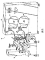
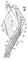
- Fig. 1 there is shown a perspective view of an adhesive application apparatus 10 according to the present invention.
- the apparatus 10 is particularly advantageous for applying an adhesive to the edges of a slit extending along a tubular body of flexible insulation tubing 20.
- the apparatus 10 can have other forms and other applications without departing from the spirit and scope of the present invention.
- the apparatus 10 is in a manufacturing line downstream of an extruder (not shown) that forms the tubular body 20.
- the apparatus 10 may also be used separately in an individual capacity.
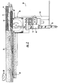
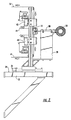
- Figs. 1-3 illustrate several views of the apparatus 10 according to the present invention.
- the apparatus 10 includes, among other components, a pair of tape reels 14 mounted to a cabinet 12.
- the cabinet 12 serves as a central storage unit for electronics and the like, as well as a foundation for several other components, as discussed more fully below.
- the apparatus 10 can be secured to an existing drive device, such as a conventional capstan 26 having a pair of opposed puller belts, using mounting brackets 24 or other securing device.
- the capstan 26 feeds the tubular body 20 having a hollow portion 21 along a path of travel such that the tubular body operably engages the apparatus 10 via guide rollers 28, 29.
- the present invention is compatible with existing capstans in the manufacturing line of the tubular body 20, thus reducing the number of parts, lowering the cost, and increasing the reliability of the apparatus 10 relative to other tape application machines which incorporate their own drive system.
- the tape reels 14 each can hold about 1500 feet of a tape, such as release tapes 16 , which are directed from the tape reels along tape feed paths and toward the tubular body 20 .
- the release tapes 16 are selected so that they each have a width equal to the width of the edges of the slit plus a nominal amount, such as about 1/4-3/4 inch, which has no adhesive applied thereto and provides a grasping point for removing the release tapes upon applying the tubular body 20 to a desired pipe to be insulated.
- the tape feed paths direct the release tapes 16 into contact with a series of rollers. At least one of the rollers 17 can provide tension to the release tapes 16 so that the release tapes are payed out at a steady rate from the tape reels 14.
- the tape reels 14 may also be connected to a brake (not shown) or other device for providing suitable tension to the release tapes 16. The rollers and brake are not required, however, but are desirable for providing a more precise operation.
- the release tapes 16 are a polymeric tape, such as Mylar, although other known release tapes may also be used.
- the release tapes 16 include release surfaces 18 to which an adhesive 41 is applied.
- the release tapes 16 travel along the tape feed paths to adhesive applicators 40.
- the adhesive applicators 40 receive the adhesive 41 from adhesive feed lines 44 and apply the adhesive to at least a portion of the release surfaces 18 by coating, extruding, or spraying.
- the adhesive applicators 40 include a slot nozzle (not shown), which provides more control than a swirling nozzle found in other systems, particularly when the adhesive applicators are moved toward or away from the release surfaces 18 of the release tapes 16 .
- the adhesive 41 is a pressure sensitive adhesive.
- the pressure sensitive adhesive may be formed with the same polymer base as the tubular body 20 for providing an improved bond therebetween.
- a common source of failure of tubular pipe insulation is the adhesion bond between the adhesive 41 and the tubular body 20 , not the cohesion bond between the adhesive applied to both edges of the slit that is pressed together to secure the tubular body around a pipe to be insulated.
- cohesion bonds are stronger than adhesion bonds.
- an adhesion bond is defined as the bond between two bodies having different compositions
- a cohesion bond is defined as a fusion bond between two bodies having similar compositions.
- the adhesive 41 is applied at an elevated temperature so that the adhesive is sufficiently flowable.
- the temperature of the adhesive 41 may vary according to several characteristics of the apparatus 10, such as line speed, type of release tapes 16, and type of adhesive.
- the temperature can be varied by a mixing pot (not shown) that feeds the adhesive 41 to the adhesive applicators 40 through the adhesive feed lines 44.
- the temperature can also be varied by an extrusion head (not shown) of the adhesive applicators 40.
- the present invention avoids complex feed paths as found in the prior art, such as in the apparatus described in U.S. Patent No.
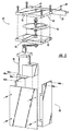
- the apparatus 10 also includes a housing member 30.
- the housing member 30 is slidably connected a frame 32.
- the frame 32 has a track 34, such that the housing member 30 may be adjusted along the track 34 and secured with a tightening device 36. This allows the housing member 30 to maintain a fixed position, yet be capable of adjustment along the track 34 according to a specific processing situation.
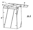
- Figs. 4 and 5 show the housing member 30 according to one embodiment of the present invention.
- the housing member 30 comprises a base portion 50 and a body portion 52 connected thereto using fasteners, such as screws 60.
- a cutting blade 54 is mounted so as to extend within the housing member 30.
- the housing member 30 supports a cutting blade 54, which is mounted within the base portion 50.
- the cutting blade 54 does not have to be mounted to the housing member 30.
- the cutting blade 54 may be mounted within the body portion 52.
- the cutting blade 54 is a circular blade that is rotatable about a central axis 68 of the cutting blade by a motor 58.
- the cutting blade 54 is secured to the base portion 50 along the central axis 68 of the cutting blade by an axle and a series of separators.
- the cutting blade 54 is stationary and has a rectangular shape, although other geometric shapes may also be used (see Figs. 12 and 13).
- the base portion 50 comprises two elements secured together with fasteners. However, the base portion 50 may be constructed as a single element.
- the base portion 50 also includes guide surfaces 56 for directing the release tapes 16 toward the tubular body 20 , as discussed more fully below.
- Fig. 6 shows a partial view of the base portion 50 and cutting blade 54 according to one embodiment of the present invention.
- the cutting blade 54 is mounted in the base portion 50 at the central axis 68 and is rotated thereabout for forming a slit in the tubular body 20 as the tubular body is fed along the path of travel.
- the cutting blade 54 is formed of a high strength material, such as zirconia or stainless steel, although other types of materials may also be used.
- the cutting blade is rotatable and has a diameter of about 7 inches, but the diameter may vary according to particular processing conditions.
- the base portion 50 includes an entry end 57 and an exit end 59 relative to the tape feed paths.
- the guide surfaces 56 extend between the entry end 57 and the exit end 59 for directing the release tapes 16 toward the tubular body 20 .
- Fig. 7 shows a cross-sectional side view of one embodiment of the base portion 50 and the cutting blade 54 .
- the cutting blade 54 is disposed within the base portion 50 and mounted thereto at the central axis 68 of the cutting blade.
- the central axis 68 is positioned in the base portion 50 such that the cutting blade 54 extends past the exit end 59 .
- the guide surfaces 56 are operable for directing the release tapes 16 through the base portion 50 by entering at the entry end 57 and exiting at the exit end 59.
- the release surfaces 18 enter the base portion 50 facing the cutting blade 54 and exit in a likewise manner to the body portion 52, as discussed hereinbelow.
- the guide surfaces 56 define acute angles relative to the cutting blade 54 at the entry end 57, such as about 2°, but are substantially parallel to the cutting blade at the exit end 59.
- the acute angles allow the release tapes 16 to sag or droop relatively small amounts at the entry end 57 without contacting the cutting blade 54.
- the guide surfaces 56 may be substantially parallel to the cutting blade 54 from the entry end 57 to the exit end 59 without affecting performance.
- Fig. 8 shows a perspective view of the housing member 30 according to one embodiment of the present invention.
- the release tapes 16 having the adhesive 41 applied to the release surfaces 18 are shown entering the base portion 50 at the entry end 57 from the tape feed paths via the guide surfaces 56 and travelling along the guide surfaces to the body portion 52 .
- the release tapes 16 exit the base portion 50 and enter the body portion 52 at an opening 63 defined therein.
- the opening 63 may be sized to accommodate at least the release tapes 16 and a portion of the cutting blade 54 , although the opening may be smaller or larger.
- Figs. 9-12 show various illustrations of the body portion 52 of the housing member 30 according to the present invention.
- the body portion 52 is removably attached to the base portion 50 with screws via attachment holes 61 .
- the body portion 52 is constructed of more than one piece of material, although the body portion may be made from a single piece of material.
- the body portion 52 comprises a support member 66 and a leg portion 67.
- the leg portion 67 comprises three layers secured together (not shown), although the leg portion may be machined from a single piece of material, such as by EDM techniques.
- the support member 66 defines the opening 63 for receiving the release tapes 16 and, in one embodiment, a portion of the cutting blade 54.
- the support member 66 is adapted for securing the body portion 52 to the base portion 50 via screws 60.
- the leg portion 67 includes a pair of exterior surfaces 42 extending away from the support member 66 such that the opening 63 extends into the leg portion. As shown in Figs. 9-12, the leg portion 67 includes two exterior surfaces 42 that are substantially parallel to one another, as well as a bottom surface 69 .
- the exterior surfaces 42 are adapted for receiving the release tapes 16 and directing the release tapes along lines parallel with the path of travel of the tubular body 20. In particular, the exterior surfaces 42 are positioned such that the release tapes 16 are directed between the exterior surfaces and the tubular body 20, and the release surfaces 18 having the adhesive 41 applied thereto are applied to the edges of the slit formed in the tubular body, as discussed more fully below.
- the substantially parallel exterior surfaces 42 provide an advantage over exterior surfaces defining an acute angle therebetween of better radial placement of the release tapes 16 on the exterior surfaces 42.
- the bottom surface 69 defines a slot 70 at a forward end of the bottom surface, although the cutting blade 54 does not extend through the slot 70 for safety reasons. Rather, the slot 70 provides an easy access to the cutting blade 54 for cleaning purposes.
- the leg portion 67 is positioned such that the leg portion covers a portion of the cutting blade 54 as the cutting blade extends through the body portion 52. More specifically, the cutting blade 54 extends into the body portion 52 and is partially covered downstream by the leg portion 67, thus leaving an upstream exposed cutting surface 55 to form a slit in the tubular body 20 as the tubular body is fed along the path of travel by the capstan.
- the exposed cutting surface 55 is best shown in Figs. 8 and 12.
- the exposed cutting surface 55 is at a forward end of the body portion 52 defined by leading edges 62 of the leg portion 67 (see Figs. 9 and 12). As such, the cutting blade 54 cuts the tubular body 20 and forms a slit having two opposing edges.
- the tubular body then engages the release tapes 16 on the body portion 52 at the leading edges 62 wherein the cutting blade 54 is interposed between the opposing edges.
- the opposing edges of the slit are then directed along the exterior surfaces 42 such that the edges are no longer in contact with the cutting blade 54, thereby reducing the friction created between the cutting blade and the tubular body 20 that is a disadvantage of conventional systems.
- the leading edges 62 may also serve other important functions, as described hereinbelow.
- the leg portion 67 may also include thicker portions or projections 64 extending away from the leg portion for providing urging forces against the release tapes 16 and the tubular body 20 as the release tapes and tubular body are fed along the path of travel.
- the projections 64 are located at a trailing end of the leg portion 67 and have a flared shape. As the tubular body 20 and the release tapes 16 applied thereto pass over the projections 64, the projections urge against the release tapes such that the release tapes are pressed toward the tubular body, thus improving the bond between the adhesive 41 and the edges of the slit.
- the projections 64 provide an added level of improvement desirable in most applications.
- the leading edges 62 defined by the exterior surfaces 42 are positioned to receive the release tapes 16 from the tape feed paths via the guide surfaces 56 and direct the release tapes around the leading edges 62 approximately 90° so that the release tapes travel along the exterior surfaces 42 in lines parallel to the path of travel such that the adhesive 41 is applied to the edges of the slit formed in the tubular body 20.
- the leading edges 62 and guide surfaces 56 may be sized slightly larger than the release tapes 16, so that the release tapes 16 may move laterally within the guide surfaces 56 and along the leading edges 62 by laterally adjusting the tape feed paths relative to the guide surfaces 56 in a direction parallel with the path of travel of the tubular body 20 . Accordingly, positioning the release tapes 16 at a certain position along the leading edges 62 determines where the release tapes 16 are applied to the edges of the slit.
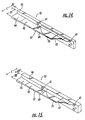
- Figures 12 and 13 show one embodiment of the body portion 52 according to the present invention. More specifically, Figures 12 and 13 illustrate the body portion 52 having a stationary blade 54 interposed between the leading edges 62 of the body portion. Such a design results in reduced costs, such as in capital expenditure, maintenance and reliability costs, compared to the design described above using a rotating cutting blade.
- the stationary blade 54 is secured within the housing member 52 and is positioned at an angle between about 32°- 50° relative to the path of travel of the tubular body 20, and in particular about 32°- 35°.
- the stationary blade 54 comprises zirconia, and is available from Specialty Blades, Inc. (http: ⁇ www.specialtyblades.com).
- the stationary blade 54 shown in Figures 12 and 13 allows the exterior surfaces 42 of the body portion 52 to be shorter along the path of travel of the tubular body 20 compared to a rotating cutting blade because the exterior surfaces have less surface area of the stationary blade to cover compared to the surface area of a rotating cutting blade. Furthermore, using the body portion 52 incorporating the stationary blade 54 shown in Figures 12 and 13 results in a reduced amount of polymer dust generated by slitting the tubular body 20 compared to incorporating a rotating cutting blade.
- the apparatus 10 allows for easy changeovers from processing one size tubular body to another size tubular body.
- Figs. 14 and 15 show two embodiments of the body portion 52 of the housing member, wherein the support member 66 and leg portion 67 may be sized according to a particularly sized tubular body.
- the cutting blade and base portion do not have to be exchanged when changing over from one size tubular body to another size tubular body. Further adjustments may also be made by moving the housing member 30 along the track 34 and securing the housing member thereto using the tightening device 36 (see Fig. 1).
- Figs. 14 and 15 show two embodiments of the body portion 52 to highlight the advantageous changeover feature described above.
- the support member 66 of the body portion 52 shown in Fig. 14 has a width along a radial axis (relative to the tube) of A1
- the leg portion 67 has a width in the same axis of B1 .
- the overall width of the body portion 52 is shown as C . If a tubular body having a smaller diameter, for example, is to be processed, the apparatus can be easily adapted to the smaller tubular body by first removing the body portion 52 by unscrewing the screws from the base portion via the attachment holes 61 and installing a suitable body portion 52 having a relatively wider support member 66 , such as the body portion shown in Fig.
- the dimensions of the support member 66 and the leg portion 67 determine the size of the cutting surface 55 of the cutting blade 54 (see Fig. 8).
- the cutting surface 55 decreases as the support member 66 increases in width and the leg portion 67 decreases in width (for example, A1 to A2 and B1 to B2 , respectively), while the cutting surface 55 increases as the support member decreases in width and the leg portion increases in width.
- the apparatus 10 may easily accommodate tubular bodies within a wide range of diameters with minimal changeover steps and simplicity of parts.
- the operation of the apparatus 10 and method of slitting the tubular body 20 and applying the adhesive 41 to the edges of the slit formed in the tubular body are as follows:
- the tubular body 20 is fed along the path of travel by a capstan 26 or other device so that the tubular body engages the housing member 30.
- the release tapes 16 are advanced along the tape feed paths toward the tubular body 20 and the adhesive 41 is applied to the release surfaces 18 at the adhesive applicators 40.
- the release tapes 16 are advanced to the base portion 50 of the housing member 30 and along the guide surfaces 56 thereof toward the body portion 52.
- the tubular body 20 engages the cutting surface 55 of the cutting blade 54 such that a slit having opposing edges is formed by the cutting blade, which is interposed therebetween.
- the release tapes 16 are advanced through the opening 53 in the body portion 52 to the leading edges 62, where the release tapes are redirected approximately 90° along the exterior surfaces 42 of the body portion.
- the edges of the slit pass over the leading edges 62 of the leg portion 67 so as to remove the edges from contact with the cutting blade 54.
- the edges of the slit engage the release tapes 16, and more specifically the release surfaces 18 having the adhesive 41 applied thereto, such that the adhesive 41 is applied to the edges of the slit.
- the tubular body 20 is advanced to the projections 64, wherein the projections urge the release tapes 16 against the tubular body for improving the bond between the adhesive 41 and the edges of the slit.
- the tubular body 20 having the adhesive 41 and release tapes 16 applied thereto may then be advanced further along the path of travel for further processing.
Landscapes
- Engineering & Computer Science (AREA)
- Mechanical Engineering (AREA)
- General Engineering & Computer Science (AREA)
- Life Sciences & Earth Sciences (AREA)
- Forests & Forestry (AREA)
- Manufacturing & Machinery (AREA)
- Adhesive Tape Dispensing Devices (AREA)
- Coating Apparatus (AREA)
Applications Claiming Priority (2)
| Application Number | Priority Date | Filing Date | Title |
|---|---|---|---|
| US560407 | 1990-07-30 | ||
| US09/560,407 US6428651B1 (en) | 2000-04-27 | 2000-04-27 | Method and apparatus for applying adhesives to the edges of a slit tube |
Publications (2)
| Publication Number | Publication Date |
|---|---|
| EP1151831A2 true EP1151831A2 (de) | 2001-11-07 |
| EP1151831A3 EP1151831A3 (de) | 2003-09-17 |
Family
ID=24237679
Family Applications (1)
| Application Number | Title | Priority Date | Filing Date |
|---|---|---|---|
| EP01303702A Withdrawn EP1151831A3 (de) | 2000-04-27 | 2001-04-23 | Verfahren und Vorrichtung zur Auftragung von Klebestoffen auf die Kanten eines geschlitzten Rohres |
Country Status (3)
| Country | Link |
|---|---|
| US (1) | US6428651B1 (de) |
| EP (1) | EP1151831A3 (de) |
| CA (1) | CA2344009C (de) |
Families Citing this family (5)
| Publication number | Priority date | Publication date | Assignee | Title |
|---|---|---|---|---|
| US7357052B2 (en) * | 2002-10-01 | 2008-04-15 | Eveready Battery Company, Inc. | Zirconia based blades and foils for razors and a method for producing same |
| JP4248510B2 (ja) * | 2005-03-24 | 2009-04-02 | 株式会社東芝 | 計算機システム、ディスク装置およびデータ更新制御方法 |
| US8747173B1 (en) | 2011-06-10 | 2014-06-10 | Hickory Springs Manufacturing Company | Flotation device |
| PL3164250T3 (pl) * | 2014-07-02 | 2019-03-29 | Panotec Srl | Tnące urządzenie do cięcia względnie sztywnego materiału |
| CN111270507B (zh) * | 2020-04-09 | 2021-10-01 | 中南大学湘雅三医院 | 医用3m胶布自动裁剪装置 |
Family Cites Families (32)
| Publication number | Priority date | Publication date | Assignee | Title |
|---|---|---|---|---|
| US2717848A (en) | 1953-07-17 | 1955-09-13 | Jaye Corp | Pipe covering |
| US3691990A (en) * | 1971-05-13 | 1972-09-19 | Armstrong Cork Co | Apparatus for applying adhesive to the edges of a slit tube |
| FR2271006A1 (en) * | 1974-05-17 | 1975-12-12 | Saint Gobain | Finned torpedo for slitting tubular profiles - for making wrap round insulation sleeve without generating dust |
| US4022248A (en) | 1975-09-24 | 1977-05-10 | Owens-Corning Fiberglas Corporation | Pipe having insulating material and cover and having two strips of self-sealing adhesive material |
| US4584217A (en) | 1977-09-29 | 1986-04-22 | Morgan Adhesives Company | Composite pressure sensitive adhesive construction |
| US4243453A (en) | 1979-05-14 | 1981-01-06 | Morgan Adhesives Company | Methods for application and use of a composite pressure sensitive adhesive construction |
| US4389270A (en) | 1979-05-14 | 1983-06-21 | Morgan Adhesives Company | Method for application of composite pressure sensitive adhesive |
| EP0152393A3 (de) * | 1984-01-27 | 1985-09-18 | Pla-Ma Belgium N.V. | Vorrichtung für das Behandeln einer Isolierhülle für Röhren |
| US4606957A (en) | 1985-01-04 | 1986-08-19 | Venture Tape Corp. | Pipe insulation with flap for extreme weather applications |
| US4748060A (en) | 1986-12-29 | 1988-05-31 | Armstrong World Industries, Inc. | Flexible pipe covering seam sealing |
| DE3707316A1 (de) * | 1987-03-07 | 1988-09-15 | Wolfgang Pfitzmann | Verfahren und vorrichtung zur herstellung von geschlitzten isolierschlaeuchen fuer rohre oder dergleichen |
| US4937111A (en) | 1987-04-02 | 1990-06-26 | Compac Corporation | Adhesive tape for insulation application |
| US4778703A (en) | 1987-04-02 | 1988-10-18 | Compac Corporation | Adhesive tape for insulation application |
| US4772507A (en) | 1987-07-20 | 1988-09-20 | Leo Jr Joseph P | Pipe hanger insulation support |
| US4823845A (en) | 1987-09-04 | 1989-04-25 | Manville Corporation | Pipe insulation |
| US4946732A (en) | 1987-09-15 | 1990-08-07 | Venture Tape Corp. | Insulation with tape adhering surface |
| US4842908A (en) | 1987-09-15 | 1989-06-27 | Venture Tape Corp. | Insulation with tape adhering surface |
| US5006185A (en) | 1987-12-29 | 1991-04-09 | Atlantic Richfield Company | Pipe insulation and corrosion protection system |
| US4874648A (en) | 1988-03-17 | 1989-10-17 | Sorrento Engineer, Inc. | Method of making flame resistant polyimide foam insulation and the resulting insulation |
| US5143574A (en) | 1988-09-26 | 1992-09-01 | Morgan Adhesives Co. | Storage stable adhesive and bonding method employing the same |
| US5427849A (en) | 1990-02-28 | 1995-06-27 | Morgan Adhesive Company | Pressure sensitive adhesive tape with central release liner and its use on a jacket portion of insulation member |
| US5141793A (en) | 1990-11-16 | 1992-08-25 | Compac Corporation | Pressure sensitive tape for insulation applications |
| US5417901A (en) | 1992-12-24 | 1995-05-23 | Industrial Thermo Polymers Limited | Method of forming pipe insulation with prestressed tape closure |
| US5421371A (en) | 1993-04-19 | 1995-06-06 | Nmc Of North America, Inc. | Multi-layered bonded closure system for foam tubes or profiles |
| US5360048A (en) | 1993-05-27 | 1994-11-01 | Nmc Of North America, Inc. | Surface coated, easily mountable cushioning member and method of manufacture |
| WO1995019523A1 (en) | 1994-01-14 | 1995-07-20 | Rockwool International A/S | Method and apparatus for insulating |
| US5558739A (en) | 1994-10-19 | 1996-09-24 | Insulation Materials Corporation Of America | Apparatus and process for applying glue to edges of insulation tube slit |
| US5934337A (en) | 1995-06-06 | 1999-08-10 | Fiala; Anthony | Field installed insulating system |
| US5783274A (en) | 1995-07-07 | 1998-07-21 | Morgan Adhesives Company | Pressure sensitive adhesive closure system for foam insulation |
| US5806188A (en) * | 1996-06-24 | 1998-09-15 | Caraballo; Philip J. | Slotter |
| US5904970A (en) | 1997-06-13 | 1999-05-18 | Nomaco, Inc. | Integrally bonded, multilayer foamed product |
| US5964252A (en) | 1997-12-18 | 1999-10-12 | Morgan Adhesives Company | Adhesive closure system with an abridged release liner |
-
2000
- 2000-04-27 US US09/560,407 patent/US6428651B1/en not_active Expired - Lifetime
-
2001
- 2001-04-17 CA CA002344009A patent/CA2344009C/en not_active Expired - Lifetime
- 2001-04-23 EP EP01303702A patent/EP1151831A3/de not_active Withdrawn
Also Published As
| Publication number | Publication date |
|---|---|
| EP1151831A3 (de) | 2003-09-17 |
| CA2344009C (en) | 2004-08-24 |
| US6428651B1 (en) | 2002-08-06 |
| CA2344009A1 (en) | 2001-10-27 |
Similar Documents
| Publication | Publication Date | Title |
|---|---|---|
| US6306235B1 (en) | Spiral formed products and method of manufacture | |
| US4995928A (en) | Method and apparatus for forming and transporting elastic ribbons | |
| EP0089679A2 (de) | Verfahren und Vorrichtung zur Herstellung von Teilen insbesondere von wiederverschliessbaren Behältern | |
| EP0220950A2 (de) | Verfahren und Vorrichtung zur Bildung und Beförderung von elastischen Bändern | |
| EP0514226A1 (de) | Verfahren und Vorrichtung zum Wickeln einer Bahn | |
| JPH10318309A (ja) | 摩擦材料から成る多数のセグメントを有したコアプレートの製造方法 | |
| US4923546A (en) | Method and apparatus for forming a butt splice | |
| JP2006502931A (ja) | ウエブ材料のログの製造方法と前記方法を実行する巻き戻し機 | |
| US5833592A (en) | Method and apparatus for enhancing seam unifority in spirally wound tubes | |
| US6428651B1 (en) | Method and apparatus for applying adhesives to the edges of a slit tube | |
| US4880178A (en) | Roll unwind butt splicer | |
| JPH10505279A (ja) | ウエブコーティング装置 | |
| JP2022520879A (ja) | フィラメント接着剤ディスペンサシステム | |
| KR19990022223A (ko) | 무심 접착 테이프 권취 맨드럴 및 방법 | |
| CN112850317B (zh) | 泡棉贴胶机构 | |
| CN221041164U (zh) | 极片加工设备及电池生产线 | |
| US10308460B2 (en) | Web transfer device with vacuum hood and methods for web transfer | |
| MXPA01004192A (en) | Method and apparatus for applying adhesives to the edges of | |
| US5558739A (en) | Apparatus and process for applying glue to edges of insulation tube slit | |
| CN214733314U (zh) | 泡棉贴胶机构 | |
| JP2000135747A (ja) | 接着装置 | |
| JP3100480B2 (ja) | 管状被覆材の製造方法及び製造装置 | |
| JP2977769B2 (ja) | 粘着テープ付マスキングシートロール製造装置 | |
| US6481664B1 (en) | Automatic tape crossover | |
| CN218428545U (zh) | 一种离型膜的分切装置 |
Legal Events
| Date | Code | Title | Description |
|---|---|---|---|
| PUAI | Public reference made under article 153(3) epc to a published international application that has entered the european phase |
Free format text: ORIGINAL CODE: 0009012 |
|
| AK | Designated contracting states |
Kind code of ref document: A2 Designated state(s): AT BE CH CY DE DK ES FI FR GB GR IE IT LI LU MC NL PT SE TR |
|
| AX | Request for extension of the european patent |
Free format text: AL;LT;LV;MK;RO;SI |
|
| PUAL | Search report despatched |
Free format text: ORIGINAL CODE: 0009013 |
|
| AK | Designated contracting states |
Kind code of ref document: A3 Designated state(s): AT BE CH CY DE DK ES FI FR GB GR IE IT LI LU MC NL PT SE TR |
|
| AX | Request for extension of the european patent |
Extension state: AL LT LV MK RO SI |
|
| RIC1 | Information provided on ipc code assigned before grant |
Ipc: 7B 26D 7/34 B Ipc: 7F 16L 59/02 B Ipc: 7B 29C 65/52 B Ipc: 7B 29C 63/00 B Ipc: 7B 26D 3/00 A |
|
| STAA | Information on the status of an ep patent application or granted ep patent |
Free format text: STATUS: THE APPLICATION HAS BEEN WITHDRAWN |
|
| 18W | Application withdrawn |
Effective date: 20031031 |