EP1151875A2 - Procédé et appareil pour la mise à disposition de signaux dans des véhicules - Google Patents
Procédé et appareil pour la mise à disposition de signaux dans des véhicules Download PDFInfo
- Publication number
- EP1151875A2 EP1151875A2 EP01106484A EP01106484A EP1151875A2 EP 1151875 A2 EP1151875 A2 EP 1151875A2 EP 01106484 A EP01106484 A EP 01106484A EP 01106484 A EP01106484 A EP 01106484A EP 1151875 A2 EP1151875 A2 EP 1151875A2
- Authority
- EP
- European Patent Office
- Prior art keywords
- signal
- signals
- sensors
- transmission
- vehicle
- Prior art date
- Legal status (The legal status is an assumption and is not a legal conclusion. Google has not performed a legal analysis and makes no representation as to the accuracy of the status listed.)
- Granted
Links
- 238000000034 method Methods 0.000 title claims abstract description 12
- 230000005540 biological transmission Effects 0.000 claims abstract description 42
- 238000011156 evaluation Methods 0.000 claims abstract description 28
- 238000012545 processing Methods 0.000 claims description 14
- 230000003750 conditioning effect Effects 0.000 claims description 7
- 230000001105 regulatory effect Effects 0.000 claims 1
- 238000010586 diagram Methods 0.000 description 4
- 239000000463 material Substances 0.000 description 3
- 238000009434 installation Methods 0.000 description 2
- 238000002360 preparation method Methods 0.000 description 2
- 238000002604 ultrasonography Methods 0.000 description 2
- 239000011248 coating agent Substances 0.000 description 1
- 238000000576 coating method Methods 0.000 description 1
- 239000004020 conductor Substances 0.000 description 1
- 238000007796 conventional method Methods 0.000 description 1
- 238000013461 design Methods 0.000 description 1
- 230000001939 inductive effect Effects 0.000 description 1
- 230000000737 periodic effect Effects 0.000 description 1
Images



Classifications
-
- B—PERFORMING OPERATIONS; TRANSPORTING
- B60—VEHICLES IN GENERAL
- B60C—VEHICLE TYRES; TYRE INFLATION; TYRE CHANGING; CONNECTING VALVES TO INFLATABLE ELASTIC BODIES IN GENERAL; DEVICES OR ARRANGEMENTS RELATED TO TYRES
- B60C23/00—Devices for measuring, signalling, controlling, or distributing tyre pressure or temperature, specially adapted for mounting on vehicles; Arrangement of tyre inflating devices on vehicles, e.g. of pumps or of tanks; Tyre cooling arrangements
- B60C23/02—Signalling devices actuated by tyre pressure
- B60C23/04—Signalling devices actuated by tyre pressure mounted on the wheel or tyre
- B60C23/0408—Signalling devices actuated by tyre pressure mounted on the wheel or tyre transmitting the signals by non-mechanical means from the wheel or tyre to a vehicle body mounted receiver
-
- F—MECHANICAL ENGINEERING; LIGHTING; HEATING; WEAPONS; BLASTING
- F16—ENGINEERING ELEMENTS AND UNITS; GENERAL MEASURES FOR PRODUCING AND MAINTAINING EFFECTIVE FUNCTIONING OF MACHINES OR INSTALLATIONS; THERMAL INSULATION IN GENERAL
- F16D—COUPLINGS FOR TRANSMITTING ROTATION; CLUTCHES; BRAKES
- F16D66/00—Arrangements for monitoring working conditions, e.g. wear, temperature
- F16D66/02—Apparatus for indicating wear
- F16D66/021—Apparatus for indicating wear using electrical detection or indication means
- F16D66/026—Apparatus for indicating wear using electrical detection or indication means indicating different degrees of lining wear
-
- F—MECHANICAL ENGINEERING; LIGHTING; HEATING; WEAPONS; BLASTING
- F16—ENGINEERING ELEMENTS AND UNITS; GENERAL MEASURES FOR PRODUCING AND MAINTAINING EFFECTIVE FUNCTIONING OF MACHINES OR INSTALLATIONS; THERMAL INSULATION IN GENERAL
- F16D—COUPLINGS FOR TRANSMITTING ROTATION; CLUTCHES; BRAKES
- F16D66/00—Arrangements for monitoring working conditions, e.g. wear, temperature
- F16D2066/001—Temperature
Definitions
- the invention relates to a method and a device for providing Signals in a vehicle, in particular for processing for the vehicle essential signals.
- the invention has for its object a method for providing Signals in a vehicle, in particular for processing for the vehicle essential signals, the signals being generated by at least two sensors and the signals are transmitted to an evaluation device, to develop in such a way that with little material, inexpensive and reliable Signals are provided.
- the invention also has the task of a device to provide signals in a vehicle, in particular a Rail vehicle, in particular for the preparation of for the vehicle essential signals, comprising at least two sensors that generate signals, to further develop a transmission device and an evaluation device, that these can be produced inexpensively with relatively little material and can be installed in the respective vehicle, the method and the device should work reliably and thus contribute to the safety of the vehicle.
- This task is solved by a method for providing signals in a vehicle, in particular for processing essentials for the vehicle Signals, the signals being generated by at least two sensors and wherein the signals are transmitted to an evaluation device, which is further developed thereby is that the signals prior to transmission become a common transmission signal be linked and via a transmission path to the evaluation device be transmitted.
- the transmission path can preferably be a single-core or be a two-core cable or a radio link or an ultrasound or infrared range.
- a single-core cable the vehicle body used as mass, whereas the use of a two-wire Cable leads to less interference compared to a single-core cable.
- One of the signals in the transmission signal preferably represents a carrier signal represents, on which at least one further signal is modulated. It is preferred the carrier signal is available from a sensor directly or after the sensor posed. This preferred embodiment of the invention makes it relative easily possible the information contained in the respective signals To resolve reception in the evaluation device accordingly into individual information, so that these are then used to control and / or regulate the vehicle and / or can be forwarded to display devices.
- the carrier signal is preferably a square-wave signal, in particular one of one Square-wave signal generated by the speed sensor.
- the pulse generators preferably comprise an inductive one Element or a Hall sensor.
- the at least one further signal in the carrier signal is preferably such modulated that the information contained in the least one signal from the Edge distance, the edge width, the distance of the minima or maxima and / or the amplitude of the carrier signal can be derived.
- At least one more signal can be, for example, an analog value that indicates a wheel bearing temperature and derives, for example, from a thermocouple or a pyrometer. This would then be a voltage, for example in the carrier signal as an amplitude is hidden or modulated.
- a multiplier is preferably used for this.
- thermocouple voltage the carrier signal are multiplied, resulting in amplitudes from 0.1 volts to 0.5 Volts would result.
- thermocouple voltage is amplified beforehand by an amplifier.
- the at least one further signal preferably contains information about the Pad thickness of a wheel brake and / or the temperature of the wheel bearing.
- the covering thickness a brake could, for example, preferably use a rotary potentiometer be detected to measure the wear of the brake pad.
- a device for providing signals in a vehicle in particular a rail vehicle, in particular for the preparation of for the vehicle essential signals, comprising at least two sensors that Generate signals, a transmission device and an evaluation device, thereby further developed that between the transmission device and the sensors a linkage device is provided which stores the signals from the sensors Linked transmission signal that can be transmitted via the transmission device.
- This device according to the invention can save considerable costs in connection technology and also in the assembly of the corresponding Components of the vehicles.
- the transmission device preferably comprises a single-core or two-core Cable, wherein the one transmission signal can be transmitted via the cable.
- the transmission device comprises a transmitter and a receiver. This measure can preferably save even more installation time, because part of the connecting cable that is used to transmit the signals of, for example a wheel of a vehicle to an evaluation device or an electronic one Regulation and control unit is used, is saved.
- the sender and the receiver work preferably in the infrared range, in the ultrasound range or in the high frequency range. If the evaluation device preferably uses an electronic control and / or control unit, this can be a structural unit quickly and inexpensively to be assembled.
- the evaluation device a converter which converts a frequency or a clock into a voltage is the Further processing of at least one signal is simplified.
- the Evaluation device an analog-digital converter. Through this preferred embodiment the information contained in the signal or signals can be digital are processed.
- At least one signal processing device is preferably in front of the linking device provided for processing at least one signal from a sensor.
- the signal processing device it is possible to have disturbances in relative to minimize small levels of the signals from the sensors on the transmission path.
- the respective signal is preferably amplified.
- the sensors speed sensors, temperature sensors and / or coating sensors or Pad wear sensors are preferred.
- the speed sensors can preferably speed sensors be designed inductively magnetic or as Hall sensors.
- the Temperature sensors can be, for example, a thermocouple or a pyrometer be or a PT 100.
- the lining sensor or lining wear sensor can be a resonator be a resonant circuit or a rotary potentiometer that varies depending on wear For example, a brake pad adjusts so that the resistance across this Rotary potentiometer changes with the degree of wear.
- the linking device for varying the amplitude of the Carrier signal an analog multiplier further preferably comprises the combining device a signal holding means.
- the signal holding means is used for a for example, to be able to modulate the pulse width with a uniform square-wave signal.
- the voltage of the amplitude is different, for example high voltages, for example from a pad wear sensor originate, extended or shortened.
- Fig. 1 shows schematically a first embodiment of a device according to the invention for providing signals in a rail vehicle in a block diagram representation.
- Two sensors 10 are shown. whose signals via cable 20 are led to a signal processing device 30.
- the signals are amplified and / or in one Voltage signal converted.
- the sensors 10 can, for example, each be a speed sensor used to measure wheel speeds finds.
- These days for example, pulse generators with magnet wheels used.
- a pole wheel 150 is shown schematically in FIG. 3, for example.
- a temperature sensor can also be used to record the wheel bearing temperature become.
- a brake pad wear sensor can be used that for example, a potentiometer that varies depending on the degree of wear of a brake pad readjusted and thus has a changing resistance.
- the sensors can, for example, in a unit with or without a signal conditioning device be arranged.
- the signal conditioning device 30 is a logic circuit 40 in Fig. 1, which shows the signals, and in particular the processed signals in this Embodiment linked together.
- a Rectangular signal which is output by the speed sensor, for example changed in amplitude by the further signal of the other sensor, for example.
- the signal linked in this way is via a transmission cable 50 passed to an evaluation device 60, which for example a control unit having.
- the evaluation device 60 the signals that are on a transmission path were again divided into individual signals that were linked can then be used for further processing.
- This further processing takes place, for example, in a control unit, by means of, for example, the essential ones Vehicle parameters such as brake pad thickness and / or wheel speed are monitored and, if necessary, for display or further processing to get redirected.
- Fig. 2 three sensors 10 are shown instead of two sensors 10, the direct Signal conditioning devices 30 in the immediate vicinity and / or one Have unit.
- the signals processed in this way are then transmitted via cable 20 led to the logic circuit 40.
- the logic circuit 40 via a transmitter 70 to the transmission signal via a transmission link 90 sent to a receiver 80, which then transmits the transmitted signal to the evaluation device 60 forwards.
- the sensors with a signal conditioning device be designed as a structural unit or as a whole as a structural unit be configured and in particular also together with the cables 20, logic circuit 40 and transmitter 70.
- the receiver 80 can be provided with the evaluation device 60 as a structural unit
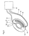
- FIG. 3 the essential elements of a braking device are shown schematically.
- a speed sensor 100 is shown that is operatively connected to a magnet wheel 150 stands and so for example magnetically the progress of the magnet wheel 150 measures and a corresponding signal on the cable 20 to the logic circuit 40 can lead.
- a lining wear sensor 110 is also shown, which is in the immediate vicinity Surrounding a brake pad 120 is arranged and for example as a Potentiometer can be designed. The respective resistances from the potentiometer are divided into corresponding voltages by applying a voltage, which are then passed via cable 20 into the logic circuit 40.
- a brake disc 130 is also shown in FIG. 3.
- Fig. 4 shows the transmitted signal, the carrier signal of the transmitted signal being a rectangular pulse, and Fig. 4 (b) also shows the transmitted signal 140, where the carrier signal is a cosine. 4 shows the respective amplitude A and also the edge spacing t p and the period T. In this diagram, the strength of the signal is thus plotted against time. In Fig. 4 (a) it is shown by arrows which are shown parallel to the abscissa and which point away from an edge of the rectangular signal that this edge is shifted to the left or to the right depending on the size of the modulated signal.
- At least one is generated by a sensor analog signal converted into a pulse by using a pulse generator. This pulse is then modulated onto the carrier signal or serves itself as Carrier signal.
Landscapes
- Engineering & Computer Science (AREA)
- Mechanical Engineering (AREA)
- General Engineering & Computer Science (AREA)
- Arrangements For Transmission Of Measured Signals (AREA)
- Valves And Accessory Devices For Braking Systems (AREA)
Applications Claiming Priority (2)
| Application Number | Priority Date | Filing Date | Title |
|---|---|---|---|
| DE10021573 | 2000-05-03 | ||
| DE2000121573 DE10021573A1 (de) | 2000-05-03 | 2000-05-03 | Verfahren und Einrichtung zur Bereitstellung von Signalen in Fahrzeugen |
Publications (3)
| Publication Number | Publication Date |
|---|---|
| EP1151875A2 true EP1151875A2 (fr) | 2001-11-07 |
| EP1151875A3 EP1151875A3 (fr) | 2003-09-17 |
| EP1151875B1 EP1151875B1 (fr) | 2006-05-17 |
Family
ID=7640668
Family Applications (1)
| Application Number | Title | Priority Date | Filing Date |
|---|---|---|---|
| EP20010106484 Expired - Lifetime EP1151875B1 (fr) | 2000-05-03 | 2001-03-26 | Procédé et appareil pour la mise à disposition de signaux dans des véhicules |
Country Status (2)
| Country | Link |
|---|---|
| EP (1) | EP1151875B1 (fr) |
| DE (2) | DE10021573A1 (fr) |
Cited By (2)
| Publication number | Priority date | Publication date | Assignee | Title |
|---|---|---|---|---|
| WO2003008834A1 (fr) * | 2001-07-17 | 2003-01-30 | Federal-Mogul Friction Products Limited | Dispositif indiquant l'etat de la garniture de frein d'un vehicule automobile |
| WO2009077075A1 (fr) * | 2007-12-14 | 2009-06-25 | Pex Kabeltechnik Gmbh | Système de freinage pour un véhicule |
Families Citing this family (2)
| Publication number | Priority date | Publication date | Assignee | Title |
|---|---|---|---|---|
| DE102004045974A1 (de) | 2004-09-22 | 2006-03-23 | Mekra Lang Gmbh & Co. Kg | System zur Übertragung von Signalen in einem Kraftfahrzeug |
| DE102011088746A1 (de) * | 2011-12-15 | 2013-06-20 | Continental Teves Ag & Co. Ohg | Verfahren zum Messen des Verschleißes und/oder der Beschädigung eines Radlagers |
Family Cites Families (7)
| Publication number | Priority date | Publication date | Assignee | Title |
|---|---|---|---|---|
| DE3701082A1 (de) * | 1987-01-16 | 1988-07-28 | Ziegler Horst | Einrichtung zur fernmessung der temperatur |
| FR2624802B1 (fr) * | 1987-12-18 | 1990-04-13 | Michelin & Cie | Codage de la valeur de plusieurs grandeurs mesurees dans un pneumatique |
| DE3912439A1 (de) * | 1989-04-15 | 1990-10-18 | Vdo Schindling | Signaluebertragungssystem |
| DE4322811A1 (de) * | 1992-07-08 | 1994-02-10 | Duerrwaechter E Dr Doduco | Einrichtung, insbesondere in Fahrzeugen, zum leitungsgebundenen Übertragen von elektrischen Signalen |
| DE19634714B4 (de) * | 1996-08-28 | 2007-08-16 | Continental Teves Ag & Co. Ohg | Anordnung für ein Kraftfahrzeug-Regelungssystem |
| DE19634715A1 (de) * | 1996-08-28 | 1998-03-05 | Teves Gmbh Alfred | Anordnung zur Erfassung des Drehverhaltens eines Rades |
| DE19753467A1 (de) * | 1997-12-02 | 1999-08-19 | Siemens Ag | Schaltung zur Informations- und Energieübertragung in einem Kraftfahrzeug |
-
2000
- 2000-05-03 DE DE2000121573 patent/DE10021573A1/de not_active Withdrawn
-
2001
- 2001-03-26 DE DE50109782T patent/DE50109782D1/de not_active Expired - Lifetime
- 2001-03-26 EP EP20010106484 patent/EP1151875B1/fr not_active Expired - Lifetime
Non-Patent Citations (1)
| Title |
|---|
| None |
Cited By (2)
| Publication number | Priority date | Publication date | Assignee | Title |
|---|---|---|---|---|
| WO2003008834A1 (fr) * | 2001-07-17 | 2003-01-30 | Federal-Mogul Friction Products Limited | Dispositif indiquant l'etat de la garniture de frein d'un vehicule automobile |
| WO2009077075A1 (fr) * | 2007-12-14 | 2009-06-25 | Pex Kabeltechnik Gmbh | Système de freinage pour un véhicule |
Also Published As
| Publication number | Publication date |
|---|---|
| EP1151875A3 (fr) | 2003-09-17 |
| EP1151875B1 (fr) | 2006-05-17 |
| DE10021573A1 (de) | 2001-11-15 |
| DE50109782D1 (de) | 2006-06-22 |
Similar Documents
| Publication | Publication Date | Title |
|---|---|---|
| EP3489712B1 (fr) | Système radar et procédé de fonctionnement d'un système radar | |
| DE102020133248B4 (de) | Haptische Bedieneinrichtung mit einer magnetorheologischen Bremseinrichtung, sowie Verfahren | |
| DE19634714B4 (de) | Anordnung für ein Kraftfahrzeug-Regelungssystem | |
| DE69112183T2 (de) | Passive Sensoreinrichtung zur Überwachung eines Fahrzeugreifens und zur Messung der Rotationsparameter des Rades. | |
| DE10243127B4 (de) | Sensorvorrichtung zur Erfassung der Drehzahl eines Fahrzeugrades | |
| WO1998025148A2 (fr) | Procede et circuit pour transmettre des donnees de vitesse de rotation et des donnees supplementaires | |
| WO1998009173A1 (fr) | Dispositif de detection du comportement de rotation d'une roue | |
| DE102017107982A1 (de) | Bremsanlagen-telemetriesysteme und verfahren | |
| DE102015122194A1 (de) | Verfahren zur Maskierung und/oder zur Reduzierung störender Geräusche oder deren Auffälligkeit bei dem Betrieb eines Kraftfahrzeugs | |
| DE102016216280A1 (de) | Gleitschiene für ein Umschlingungsmittel eines Umschlingungsgetriebes und Messverfahren zum Ermitteln eines anliegenden Drehmoments an einem Kegelscheibenpaar | |
| EP3031684A1 (fr) | Disque de frein a dispositif de capteur integre, systeme de freinage et vehicule, utilisation et procede comprenant respectivement un tel systeme de freinage | |
| EP0785118A3 (fr) | Dispositif d'actionnement des freins de véhicules, notamment pour véhicules à moteur | |
| DE2448435C3 (de) | Vorrichtung zum Überprüfen einer Blockierschutzvorrichtung für Fahrzeugbremsen | |
| EP3615836B1 (fr) | Détection combinée de l'usure d'éléments d'un système de freinage, en particulier d'un véhicule à moteur | |
| DE102007047547A1 (de) | Vorrichtung und Verfahren zum Erfassen einer Betätigungskraft eines Bremspedals | |
| EP1151875A2 (fr) | Procédé et appareil pour la mise à disposition de signaux dans des véhicules | |
| EP3074260A1 (fr) | Différentiel actif et véhicule automobile | |
| DE102020126971A1 (de) | Haptische Bedieneinrichtung mit einer magnetorheologischen Bremseinrichtung | |
| DE102008061696A1 (de) | Elektromechanische Lenkung und Verfahren zur Bestimmung eines Fahrwegzustands | |
| DE102015111901A1 (de) | Anordnung und Verfahren zur Drehmomentmessung für rotierende Antriebe oder Maschinen | |
| DE102019125697B4 (de) | Verfahren zur Ermittlung eines Ausgangsdrehmomentes in einem lastschaltfähigen Antriebssystem in einem Fahrzeug | |
| EP2196698A2 (fr) | Elément de commutation d'engrenage | |
| EP2518577A1 (fr) | Méthode et appareil pour faire fonctionner un positionneur avec la capacité de communiquer en mode digital e analogue à travers une seule boucle de courrant | |
| DE102009037382B4 (de) | Verfahren und System zum Einschleifen einer Feststellbremse eines Kraftfahrzeugs | |
| DE102014207766A1 (de) | 3-Achsen-Inertialsensor mit 2-Achsen-Inertialsensor überwachen |
Legal Events
| Date | Code | Title | Description |
|---|---|---|---|
| PUAI | Public reference made under article 153(3) epc to a published international application that has entered the european phase |
Free format text: ORIGINAL CODE: 0009012 |
|
| AK | Designated contracting states |
Kind code of ref document: A2 Designated state(s): AT BE CH CY DE DK ES FI FR GB GR IE IT LI LU MC NL PT SE TR |
|
| AX | Request for extension of the european patent |
Free format text: AL;LT;LV;MK;RO;SI |
|
| PUAL | Search report despatched |
Free format text: ORIGINAL CODE: 0009013 |
|
| AK | Designated contracting states |
Kind code of ref document: A3 Designated state(s): AT BE CH CY DE DK ES FI FR GB GR IE IT LI LU MC NL PT SE TR |
|
| AX | Request for extension of the european patent |
Extension state: AL LT LV MK RO SI |
|
| 17P | Request for examination filed |
Effective date: 20040317 |
|
| AKX | Designation fees paid |
Designated state(s): DE |
|
| 17Q | First examination report despatched |
Effective date: 20041029 |
|
| GRAP | Despatch of communication of intention to grant a patent |
Free format text: ORIGINAL CODE: EPIDOSNIGR1 |
|
| GRAS | Grant fee paid |
Free format text: ORIGINAL CODE: EPIDOSNIGR3 |
|
| GRAA | (expected) grant |
Free format text: ORIGINAL CODE: 0009210 |
|
| RAP1 | Party data changed (applicant data changed or rights of an application transferred) |
Owner name: KNORR-BREMSE SYSTEME FUER NUTZFAHRZEUGE GMBH |
|
| AK | Designated contracting states |
Kind code of ref document: B1 Designated state(s): DE |
|
| REF | Corresponds to: |
Ref document number: 50109782 Country of ref document: DE Date of ref document: 20060622 Kind code of ref document: P |
|
| PLBE | No opposition filed within time limit |
Free format text: ORIGINAL CODE: 0009261 |
|
| STAA | Information on the status of an ep patent application or granted ep patent |
Free format text: STATUS: NO OPPOSITION FILED WITHIN TIME LIMIT |
|
| 26N | No opposition filed |
Effective date: 20070220 |
|
| PGFP | Annual fee paid to national office [announced via postgrant information from national office to epo] |
Ref country code: DE Payment date: 20190325 Year of fee payment: 19 |
|
| REG | Reference to a national code |
Ref country code: DE Ref legal event code: R119 Ref document number: 50109782 Country of ref document: DE |
|
| PG25 | Lapsed in a contracting state [announced via postgrant information from national office to epo] |
Ref country code: DE Free format text: LAPSE BECAUSE OF NON-PAYMENT OF DUE FEES Effective date: 20201001 |