EP1151878A2 - Système de circuit secondaire pour le chauffage et réfrigération de l'habitacle d'un véhicule automobile - Google Patents
Système de circuit secondaire pour le chauffage et réfrigération de l'habitacle d'un véhicule automobile Download PDFInfo
- Publication number
- EP1151878A2 EP1151878A2 EP01201257A EP01201257A EP1151878A2 EP 1151878 A2 EP1151878 A2 EP 1151878A2 EP 01201257 A EP01201257 A EP 01201257A EP 01201257 A EP01201257 A EP 01201257A EP 1151878 A2 EP1151878 A2 EP 1151878A2
- Authority
- EP
- European Patent Office
- Prior art keywords
- heat exchanger
- vehicle
- coolant
- fluid heat
- refrigerant
- Prior art date
- Legal status (The legal status is an assumption and is not a legal conclusion. Google has not performed a legal analysis and makes no representation as to the accuracy of the status listed.)
- Granted
Links
Images


Classifications
-
- B—PERFORMING OPERATIONS; TRANSPORTING
- B60—VEHICLES IN GENERAL
- B60H—ARRANGEMENTS OF HEATING, COOLING, VENTILATING OR OTHER AIR-TREATING DEVICES SPECIALLY ADAPTED FOR PASSENGER OR GOODS SPACES OF VEHICLES
- B60H1/00—Heating, cooling or ventilating devices
- B60H1/00321—Heat exchangers for air-conditioning devices
- B60H1/00342—Heat exchangers for air-conditioning devices of the liquid-liquid type
-
- B—PERFORMING OPERATIONS; TRANSPORTING
- B60—VEHICLES IN GENERAL
- B60H—ARRANGEMENTS OF HEATING, COOLING, VENTILATING OR OTHER AIR-TREATING DEVICES SPECIALLY ADAPTED FOR PASSENGER OR GOODS SPACES OF VEHICLES
- B60H1/00—Heating, cooling or ventilating devices
- B60H1/00007—Combined heating, ventilating, or cooling devices
-
- F—MECHANICAL ENGINEERING; LIGHTING; HEATING; WEAPONS; BLASTING
- F28—HEAT EXCHANGE IN GENERAL
- F28D—HEAT-EXCHANGE APPARATUS, NOT PROVIDED FOR IN ANOTHER SUBCLASS, IN WHICH THE HEAT-EXCHANGE MEDIA DO NOT COME INTO DIRECT CONTACT
- F28D1/00—Heat-exchange apparatus having stationary conduit assemblies for one heat-exchange medium only, the media being in contact with different sides of the conduit wall, in which the other heat-exchange medium is a large body of fluid, e.g. domestic or motor car radiators
- F28D1/02—Heat-exchange apparatus having stationary conduit assemblies for one heat-exchange medium only, the media being in contact with different sides of the conduit wall, in which the other heat-exchange medium is a large body of fluid, e.g. domestic or motor car radiators with heat-exchange conduits immersed in the body of fluid
- F28D1/04—Heat-exchange apparatus having stationary conduit assemblies for one heat-exchange medium only, the media being in contact with different sides of the conduit wall, in which the other heat-exchange medium is a large body of fluid, e.g. domestic or motor car radiators with heat-exchange conduits immersed in the body of fluid with tubular conduits
- F28D1/0408—Multi-circuit heat exchangers, e.g. integrating different heat exchange sections in the same unit or heat exchangers for more than two fluids
-
- F—MECHANICAL ENGINEERING; LIGHTING; HEATING; WEAPONS; BLASTING
- F28—HEAT EXCHANGE IN GENERAL
- F28D—HEAT-EXCHANGE APPARATUS, NOT PROVIDED FOR IN ANOTHER SUBCLASS, IN WHICH THE HEAT-EXCHANGE MEDIA DO NOT COME INTO DIRECT CONTACT
- F28D7/00—Heat-exchange apparatus having stationary tubular conduit assemblies for both heat-exchange media, the media being in contact with different sides of a conduit wall
- F28D7/10—Heat-exchange apparatus having stationary tubular conduit assemblies for both heat-exchange media, the media being in contact with different sides of a conduit wall the conduits being arranged one within the other, e.g. concentrically
- F28D7/106—Heat-exchange apparatus having stationary tubular conduit assemblies for both heat-exchange media, the media being in contact with different sides of a conduit wall the conduits being arranged one within the other, e.g. concentrically consisting of two coaxial conduits or modules of two coaxial conduits
-
- F—MECHANICAL ENGINEERING; LIGHTING; HEATING; WEAPONS; BLASTING
- F28—HEAT EXCHANGE IN GENERAL
- F28F—DETAILS OF HEAT-EXCHANGE AND HEAT-TRANSFER APPARATUS, OF GENERAL APPLICATION
- F28F1/00—Tubular elements; Assemblies of tubular elements
- F28F1/02—Tubular elements of cross-section which is non-circular
- F28F1/022—Tubular elements of cross-section which is non-circular with multiple channels
-
- B—PERFORMING OPERATIONS; TRANSPORTING
- B60—VEHICLES IN GENERAL
- B60H—ARRANGEMENTS OF HEATING, COOLING, VENTILATING OR OTHER AIR-TREATING DEVICES SPECIALLY ADAPTED FOR PASSENGER OR GOODS SPACES OF VEHICLES
- B60H1/00—Heating, cooling or ventilating devices
- B60H1/00007—Combined heating, ventilating, or cooling devices
- B60H1/00021—Air flow details of HVAC devices
- B60H2001/00185—Distribution of conditionned air
- B60H2001/002—Distribution of conditionned air to front and rear part of passenger compartment
Definitions
- This invention relates to the selective heating and cooling of the front and rear of a vehicle interior. More particularly, the present invention relates to a heating and cooling system that uses a three-fluid heat exchanger that joins the primary and secondary loops of the heating and cooling system.
- the three-fluid heat exchanger heats and cools the front of the vehicle and heats and chills the secondary loop that flows through a two fluid heat exchanger in the rear of the vehicle.
- the invention eliminates the typical rear evaporator and heater of traditional systems and replaces them with a less expensive two fluid heat exchanger.
- the system employs a brine-refrigerant heater and the engine coolant, plus air conditioning units that are separate from the brine-refrigerant heater. Due to this arrangement, the system requires a complex array of valves and piping, to heat and cool the vehicle.
- the second main component of the invention is a subsystem where working fluid is in heat exchange relationship with the evaporator of the first system whereby the working fluid is cooled in the evaporator and is thereafter sent by a pump or fan, driven by a suitable motor, into cooling members, such as cooling coils incorporated within the seat or other items within the vehicle.
- the evaporator of the traditional air conditioning system has an add on feature which includes conduits that are held in close proximity to the evaporator. In this way, the fluid within the conduits can be cooled by the evaporator and then pumped to the seats, steering wheel, etc.
- the difficulty with this system is that there is no teaching of heating the vehicle in the front and rear and in fact there is no teaching or suggestion how to cool the vehicle in the front and rear.
- the invention requires the use of an evaporator which adds cost and a fairly inefficient heat transfer mechanism associated with the evaporator.
- the present invention overcomes the above problems associated with known attempts to effectively and efficiently heat and cool the front and rear of a vehicle.
- the present invention provides a vehicle climate control system with a separate control for the front and rear areas of the vehicle.
- the climate control system includes a three-fluid heat exchanger (refrigerant, coolant solution and air) having a first path with a first inlet and first outlet, and a second path with a second inlet and second outlet.
- the first path is adapted to communicate refrigerant between the first inlet and first outlet.
- the second path is adapted to communicate coolant between the second inlet and second outlet without the refrigerant and coolant being mixed.
- a refrigerant type loop or primary loop is provided.
- This loop includes a compressor and condenser interconnected by a refrigerant line with the refrigerant line being connected to the inlet and outlet of the first path such that the refrigerant passes through the three-fluid heat exchanger.
- the front area of the vehicle passenger compartment is cooled by this three-fluid heat exchanger and more particularly by the use of a fan blowing air across the three-fluid heat exchanger.
- a secondary loop having a dual fluid heat exchanger (coolant solution and air) and a coolant line connected to the inlet and the outlet of the second path such that the coolant flows through the three-fluid heat exchanger.
- the dual fluid heat exchanger is typically in the rear area of the vehicle passenger compartment.
- the coolant is cooled as it flows through the three-fluid heat exchanger by the refrigerant flowing through the three-fluid heat exchanger adjacent the coolant.
- the coolant is then passed through the dual fluid heat exchanger for cooling the rear passenger area of the vehicle.
- the secondary loop includes a simple fluid valve for diverting coolant from the dual fluid heat exchanger to control the cooling the rear of the vehicle.
- the climate control system of the present invention includes a heating loop having a first heating conduit and a second valve for selectively connecting the secondary loop to the engine coolant system (42, 50).
- the heating loop includes a second heating conduit and a third valve for selectively connecting the three-fluid heat exchanger to the vehicle engine coolant system (42, 50).
- the system provides a very compact unit wherein the air conditioning circuit is substantially maintained in the vehicle engine compartment, the three-fluid heat exchanger is a small compact unit which can save instrument panel space and the typical components in the rear of the vehicle are eliminated saving space and cost.
- the invention also allows for more flexibility in the placement of the heat exchangers.
- the heat exchangers can be placed in various locations in the vehicle to heat or cool specific areas for passenger comfort.
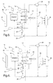
- an air conditioning system of the present invention is shown schematically at 10.
- the system includes a primary loop or refrigeration system 11 and a secondary loop or coolant system 15.
- the primary loop includes a compressor 12 that delivers compressed refrigerant to the condenser 14.
- the refrigerant then travels through an expansion device 16, through a three-fluid heat exchanger 24 into an accumulator-dehydrator 18 and back to the compressor 12.
- the three-fluid heat exchanger 24 will be discussed in greater detail below.
- the secondary loop 15 includes a pump 20 connected to a reservoir 22 which pumps a coolant, such as water-glycol, around the loop 15.
- the coolant is pumped through the three-fluid heat exchanger 24 and depending upon the three-way valve 26 through a heat exchanger 28 and then back to the reservoir 22 and pump 20.
- the three-way valve 26 is a bypass that either allows the coolant to pass through the heat exchanger 28 or merely circulate through the bypass circuit 30.
- the three-way valve 26 When air conditioning is needed in the rear of the vehicle the three-way valve 26 is turned to allow that coolant to pass through the heat exchanger 28.
- a fan is provided adjacent the heat exchanger 28 to blow the cooled air into the rear compartment.
- the fan 27, three-way valve 26 and the heat exchanger 28 define the rear mounted passenger compartment-cooling unit. In this way, the rear compartment can be cooled without the need for traditional expensive valving, rear evaporator, expansion device, etc.
- the loop 11 would preferably be substantially contained within the engine compartment of the vehicle.
- the dashed line 17 schematically illustrates the front of the instrument panel of the vehicle with air 19 being drawn in from the outside and/or passenger cabin and forced over the three-fluid heat exchanger 24.
- the coolant being pumped through the loop 15 is cooled as it passes through the three-fluid heat exchanger 24.
- the three-fluid heat exchanger 24 receives the refrigerant from the loop 11 and passes it through the inner tubes shown generally at 52 shown in figure 7.
- the coolant passes through the outer tubes 54.
- the tubes 52 and 54 allow two different heat exchange media to be in thermal contact without physical mixing.
- the inner tube 52 is an integral flat hollow tube with interior passages defined by interior webs 56.
- the outer tube 54 is relatively thicker and wider than the inner tube 52 and provides a plurality of integral spacer webs 58 on its inner surface. The edges of the spacer webs 58 terminate on an envelope that just matches the outer surface of the inner tube 52.
- heat exchanger 24 includes fins, not shown, for effective heat transfer with the third fluid, air, being blown over the fins.
- the three-fluid heat exchanger is more fully described in United States Patent No. 5,898,995, which is incorporated hereby by reference.
- a second fluid heat exchanger 32 is added to the air conditioning system of figure 1. As illustrated, the second fluid heat exchanger 32 is in series with the heat exchanger 28. It should be understood that additional heat exchangers could be added in series or parallel with additional controls to perform numerous cooling duties.
- FIG 3 an example of an air conditioning system with parallel heat exchangers is illustrated. In this view, a second heat exchanger 34 has been added in parallel. A valve 36 has been provided to allow selection between heat exchangers 28 and 34. By selecting heat exchanger 28, the coolant flow is directed to path or conduit 48 and heat exchanger 34 is bypassed. By selecting both and actuating valve 36 accordingly, both heat exchangers 28 and 34 are used. It should be appreciated that additional heat exchangers could be added in parallel and in series to the heat exchangers 28 and 34.
- FIG 4 a schematic showing the integration of the engine coolant as the coolant source is illustrated.
- both heating and air conditioning are available.
- like features from the previous embodiments of figures 1 through 3 are numbered the same and the flow path of the secondary circuit is shown in dashed lines and the paths that are closed in the secondary circuit are in solid lines.
- the flow path of the primary circuit is shown in solid lines.
- the air conditioning and heating circuit includes two additional three-way valves 38 and 40 to properly direct the coolant flow.
- the air conditioning mode is illustrated.
- the three-way valve 38 is opened to feed reservoir 22 and three-way valve 40 is opened to supply coolant to the three-fluid heat exchanger 24 from pump 20.
- the three-way valves 38 and 40 close off the flow of coolant to the engine 42 and flow line 50, respectively.
- Coolant is pumped by pump 20 from reservoir 22 through the three-way valve 40 through the three-fluid heat exchanger 24 and through either lines 30 or 48 depending upon the position of valve 26.
- the coolant is chilled as it passes through the three-fluid heat exchanger 24 by the refrigerant that is also passing through the heat exchanger 24.
- the front and rear-heating mode is illustrated.
- the engine coolant is used to heat the front and rear of the vehicle.
- the engine 42 supplies coolant to the three-fluid heat exchanger 24 through three-way valve 40.
- the air 19 blowing over the heat exchanger 24 heats the front of the vehicle.
- the coolant also travels through the secondary circuit 48 and through the heat exchanger 28 to heat the rear of the vehicle.
- the valve 26 can be switched to divert coolant from the heat exchanger 28 and only heat the front of the vehicle.
- the coolant completes the loop through valve 38 and returns to the engine 42.
- the coolant in this mode doesn't travel to the reservoir 22 or pump 20.
- the rear only heating mode is illustrated.
- the three-fluid heat exchanger 24 is bypassed and the engine coolant is directed to the heat exchanger 28 and back to the engine 42.
- the valve 40 is open to allow flow through line 50 and not from pump 20 or to heat exchanger 24.
- Line 50 delivers coolant to line 48 and with valve 26 switched, the coolant flows through heat exchanger 28.
- the bypass line 30 is closed to allow the coolant to flow through heat exchanger 28.
Landscapes
- Engineering & Computer Science (AREA)
- Physics & Mathematics (AREA)
- Thermal Sciences (AREA)
- Mechanical Engineering (AREA)
- General Engineering & Computer Science (AREA)
- Geometry (AREA)
- Air-Conditioning For Vehicles (AREA)
Applications Claiming Priority (2)
| Application Number | Priority Date | Filing Date | Title |
|---|---|---|---|
| US563385 | 2000-05-03 | ||
| US09/563,385 US6405793B1 (en) | 2000-05-03 | 2000-05-03 | Secondary loop system for passenger compartment heating and cooling |
Publications (3)
| Publication Number | Publication Date |
|---|---|
| EP1151878A2 true EP1151878A2 (fr) | 2001-11-07 |
| EP1151878A3 EP1151878A3 (fr) | 2004-01-07 |
| EP1151878B1 EP1151878B1 (fr) | 2005-11-16 |
Family
ID=24250291
Family Applications (1)
| Application Number | Title | Priority Date | Filing Date |
|---|---|---|---|
| EP01201257A Expired - Lifetime EP1151878B1 (fr) | 2000-05-03 | 2001-04-05 | Système de circuit secondaire pour le chauffage et réfrigération de l'habitacle d'un véhicule automobile |
Country Status (3)
| Country | Link |
|---|---|
| US (1) | US6405793B1 (fr) |
| EP (1) | EP1151878B1 (fr) |
| DE (1) | DE60114918T2 (fr) |
Cited By (3)
| Publication number | Priority date | Publication date | Assignee | Title |
|---|---|---|---|---|
| EP1744108A3 (fr) * | 2005-07-15 | 2008-10-08 | Modine Manufacturing Company | Arrangement dans un cycle frigorifique |
| EP1990221A1 (fr) * | 2007-05-10 | 2008-11-12 | C.R.F. Società Consortile Per Azioni | Système de conditionnement d'air pour véhicule à moteur, véhicule à moteur équipé du système |
| RU2466879C2 (ru) * | 2008-07-14 | 2012-11-20 | Чи.Эрре.Эффе. Сочиета Консортиле пер Ациони | Система кондиционирования воздуха для автомобиля и автомобиль, снабженный этой системой |
Families Citing this family (45)
| Publication number | Priority date | Publication date | Assignee | Title |
|---|---|---|---|---|
| SE9800619L (sv) * | 1998-02-27 | 1999-03-22 | Volvo Wheel Loaders Ab | Kyl- och värmesystem |
| FR2796337B1 (fr) * | 1999-07-12 | 2005-08-19 | Valeo Climatisation | Installation de chauffage-climatisation pour vehicule automobile |
| DE10124757A1 (de) * | 2000-05-26 | 2001-11-29 | Denso Corp | Fahrzeugklimaanlage mit Kältespeicher |
| US20030039298A1 (en) * | 2001-08-22 | 2003-02-27 | Lear Corporation | System and method of vehicle climate control |
| US6745829B2 (en) * | 2001-11-29 | 2004-06-08 | Visteon Global Technologies, Inc. | System for air conditioning of the interior of an automobile |
| US6889762B2 (en) * | 2002-04-29 | 2005-05-10 | Bergstrom, Inc. | Vehicle air conditioning and heating system providing engine on and engine off operation |
| US9694651B2 (en) * | 2002-04-29 | 2017-07-04 | Bergstrom, Inc. | Vehicle air conditioning and heating system providing engine on and off operation |
| DE50310683D1 (de) * | 2003-04-23 | 2008-12-04 | Fraunhofer Ges Forschung | Fluid-luft-kombiverdampfer und neues schaltkonzept für eine wärmepumpe in einem lüftungsgerät |
| US7063137B2 (en) * | 2003-07-15 | 2006-06-20 | Delphi Technologies, Inc. | Heat pump with secondary loop air-conditioning system |
| US20050066679A1 (en) * | 2003-09-30 | 2005-03-31 | Boyer Jack Clyde | Distributed operator cooling system |
| JP2007046810A (ja) * | 2005-08-08 | 2007-02-22 | Sanden Corp | ブライン式冷却システム |
| US8517087B2 (en) * | 2007-02-20 | 2013-08-27 | Bergstrom, Inc. | Combined heating and air conditioning system for vehicles |
| US8141377B2 (en) * | 2007-02-21 | 2012-03-27 | Bergstrom, Inc. | Truck electrified engine-off air conditioning system |
| US20080292945A1 (en) * | 2007-05-23 | 2008-11-27 | Ajith Kuttannair Kumar | Battery heating system and methods of heating |
| US20100018674A1 (en) * | 2008-07-22 | 2010-01-28 | Donald John Enzinna | Reservoir with moveable partition for quick recovery |
| DE102008052112B4 (de) * | 2008-10-20 | 2011-05-19 | Bombardier Transportation Gmbh | Klimatisierungsanordnung für einen Führerstand |
| US8051906B2 (en) * | 2008-11-20 | 2011-11-08 | Delphi Technologies, Inc. | Secondary loop-integral heater core and cooler |
| FR2941041B1 (fr) * | 2009-01-12 | 2010-12-31 | Valeo Systemes Thermiques | Echangeur de chaleur a accumulateur thermique |
| US8899062B2 (en) | 2011-02-17 | 2014-12-02 | Delphi Technologies, Inc. | Plate-type heat pump air conditioner heat exchanger for a unitary heat pump air conditioner |
| US9239193B2 (en) | 2011-02-17 | 2016-01-19 | Delphi Technologies, Inc. | Unitary heat pump air conditioner having a heat exchanger with an integral receiver and sub-cooler |
| US9109840B2 (en) | 2011-02-17 | 2015-08-18 | Delphi Technologies, Inc. | Unitary heat pump air conditioner having a heat exchanger with an integral accumulator |
| JP5333496B2 (ja) * | 2011-03-25 | 2013-11-06 | 株式会社デンソー | 車両用空調装置 |
| US20130081794A1 (en) * | 2011-09-30 | 2013-04-04 | Modine Manufacturing Company | Layered core heat exchanger |
| US9097174B2 (en) | 2012-05-11 | 2015-08-04 | Delphi Technologies, Inc. | System and method for conditioning intake air to an internal combustion engine |
| DE102012215971A1 (de) * | 2012-09-10 | 2014-05-28 | Bayerische Motoren Werke Aktiengesellschaft | Verfahren zum thermischen Konditionieren eines Verbrennungsmotors und/oder eines Fahrgastraums eines Fahrzeugs sowie Fahrzeug |
| EP2969613B1 (fr) | 2013-03-13 | 2018-08-08 | Bergstrom, Inc. | Système de climatisation utilisant une ventilation à récupération de chaleur pour une commande d'alimentation en air frais et de climatisation |
| EP2969615B1 (fr) | 2013-03-13 | 2021-06-02 | Bergstrom, Inc. | Système de climatisation utilisant une capacité thermique sur la base d'une détente de fluide comprimé |
| CN105873778A (zh) | 2013-11-04 | 2016-08-17 | 博格思众公司 | 低轮廓空调系统 |
| US9410509B2 (en) * | 2013-12-04 | 2016-08-09 | Delphi Technologies, Inc. | Adaptive individual-cylinder thermal state control using intake air heating for a GDCI engine |
| US9783024B2 (en) | 2015-03-09 | 2017-10-10 | Bergstrom Inc. | System and method for remotely managing climate control systems of a fleet of vehicles |
| US10006684B2 (en) | 2015-12-10 | 2018-06-26 | Bergstrom, Inc. | Air conditioning system for use in vehicle |
| US9874384B2 (en) | 2016-01-13 | 2018-01-23 | Bergstrom, Inc. | Refrigeration system with superheating, sub-cooling and refrigerant charge level control |
| US10589598B2 (en) | 2016-03-09 | 2020-03-17 | Bergstrom, Inc. | Integrated condenser and compressor system |
| FR3052856B1 (fr) * | 2016-06-21 | 2019-06-14 | Valeo Systemes Thermiques | Boucle de circulation d’un fluide refrigerant pour vehicule |
| US11530877B2 (en) * | 2016-08-01 | 2022-12-20 | Lockheed Martin Corporation | Heat exchange using phase change material |
| US12420616B2 (en) | 2016-08-22 | 2025-09-23 | Bergstrom, Inc. | Multi-compressor oil migration mitigation climate system |
| US10081226B2 (en) | 2016-08-22 | 2018-09-25 | Bergstrom Inc. | Parallel compressors climate system |
| US10562372B2 (en) | 2016-09-02 | 2020-02-18 | Bergstrom, Inc. | Systems and methods for starting-up a vehicular air-conditioning system |
| US10675948B2 (en) | 2016-09-29 | 2020-06-09 | Bergstrom, Inc. | Systems and methods for controlling a vehicle HVAC system |
| US10724772B2 (en) | 2016-09-30 | 2020-07-28 | Bergstrom, Inc. | Refrigerant liquid-gas separator having an integrated check valve |
| US10369863B2 (en) | 2016-09-30 | 2019-08-06 | Bergstrom, Inc. | Refrigerant liquid-gas separator with electronics cooling |
| US11448441B2 (en) | 2017-07-27 | 2022-09-20 | Bergstrom, Inc. | Refrigerant system for cooling electronics |
| US11420496B2 (en) | 2018-04-02 | 2022-08-23 | Bergstrom, Inc. | Integrated vehicular system for conditioning air and heating water |
| US11560042B2 (en) | 2021-06-24 | 2023-01-24 | Ford Global Technologies, Llc | Heat pump refrigerant loop arrangements |
| US11906213B2 (en) | 2021-06-24 | 2024-02-20 | Ford Global Technologies, Llc | Heat pump refrigerant loop arrangements |
Citations (4)
| Publication number | Priority date | Publication date | Assignee | Title |
|---|---|---|---|---|
| US5138851A (en) | 1990-12-14 | 1992-08-18 | Golden Empire Trading Co., Inc. | Active seat cooling system |
| US5898995A (en) | 1997-09-24 | 1999-05-04 | General Motors Corporation | Method of manufacture of a primary heat exchanger jacketed by a secondary heat exchanger |
| US5904052A (en) | 1996-09-02 | 1999-05-18 | Denso Corporation | Brine type air conditioning apparatus |
| US5910157A (en) | 1997-06-30 | 1999-06-08 | Calsonic Corporation | Automotive air conditioning system |
Family Cites Families (13)
| Publication number | Priority date | Publication date | Assignee | Title |
|---|---|---|---|---|
| US2774222A (en) * | 1954-05-19 | 1956-12-18 | Gen Motors Corp | Vehicle refrigerating apparatus |
| US2787129A (en) * | 1954-05-19 | 1957-04-02 | Gen Motors Corp | Automobile refrigerating apparatus |
| US2884768A (en) * | 1955-02-23 | 1959-05-05 | Gen Motors Corp | Automobile refrigerating apparatus |
| DE2053370A1 (de) * | 1970-10-30 | 1972-05-04 | Robert Bosch Gmbh, 7000 Stuttgart | Einrichtung zum Heizen und Kühlen von Kraftfahrzeug-Innenräumen |
| DE3518494C1 (de) * | 1985-05-23 | 1986-09-11 | Daimler-Benz Ag, 7000 Stuttgart | Waermetauscher zur Klimatisierung des Innenraumes eines Kraftfahrzeuges |
| US5265437A (en) * | 1990-11-26 | 1993-11-30 | Modine Manufacturing Co. | Automotive refrigeration system requiring minimal refrigerant |
| AU8784791A (en) * | 1990-11-26 | 1992-05-28 | Modine Manufacturing Company | Automotive refrigeration system requiring minimal refrigerant |
| US5531264A (en) * | 1994-10-19 | 1996-07-02 | Zexel Corporation | Control apparatus for a cooling unit with a heating function and a multi-compartment temperature management apparatus for a vehicle using this cooling unit |
| FR2728666A1 (fr) * | 1994-12-26 | 1996-06-28 | Valeo Thermique Habitacle | Echangeur de chaleur a trois fluides d'encombrement reduit |
| JP3525538B2 (ja) * | 1995-03-08 | 2004-05-10 | 株式会社デンソー | 車両用内燃機関の冷却系装置 |
| DE19646349B4 (de) * | 1996-11-09 | 2011-08-11 | Behr GmbH & Co. KG, 70469 | Verdampfer und damit ausgerüstete Fahrzeugklimaanlage |
| DE19749793A1 (de) * | 1997-11-11 | 1999-05-12 | Behr Gmbh & Co | Speicher thermischer Energie |
| DE19824516C2 (de) * | 1998-06-02 | 2001-09-13 | Webasto Thermosysteme Gmbh | Vorrichtung und Verfahren zum Heizen und/oder Kühlen eines Fahrzeuginnenraums |
-
2000
- 2000-05-03 US US09/563,385 patent/US6405793B1/en not_active Expired - Lifetime
-
2001
- 2001-04-05 DE DE60114918T patent/DE60114918T2/de not_active Expired - Lifetime
- 2001-04-05 EP EP01201257A patent/EP1151878B1/fr not_active Expired - Lifetime
Patent Citations (4)
| Publication number | Priority date | Publication date | Assignee | Title |
|---|---|---|---|---|
| US5138851A (en) | 1990-12-14 | 1992-08-18 | Golden Empire Trading Co., Inc. | Active seat cooling system |
| US5904052A (en) | 1996-09-02 | 1999-05-18 | Denso Corporation | Brine type air conditioning apparatus |
| US5910157A (en) | 1997-06-30 | 1999-06-08 | Calsonic Corporation | Automotive air conditioning system |
| US5898995A (en) | 1997-09-24 | 1999-05-04 | General Motors Corporation | Method of manufacture of a primary heat exchanger jacketed by a secondary heat exchanger |
Cited By (3)
| Publication number | Priority date | Publication date | Assignee | Title |
|---|---|---|---|---|
| EP1744108A3 (fr) * | 2005-07-15 | 2008-10-08 | Modine Manufacturing Company | Arrangement dans un cycle frigorifique |
| EP1990221A1 (fr) * | 2007-05-10 | 2008-11-12 | C.R.F. Società Consortile Per Azioni | Système de conditionnement d'air pour véhicule à moteur, véhicule à moteur équipé du système |
| RU2466879C2 (ru) * | 2008-07-14 | 2012-11-20 | Чи.Эрре.Эффе. Сочиета Консортиле пер Ациони | Система кондиционирования воздуха для автомобиля и автомобиль, снабженный этой системой |
Also Published As
| Publication number | Publication date |
|---|---|
| EP1151878B1 (fr) | 2005-11-16 |
| EP1151878A3 (fr) | 2004-01-07 |
| US6405793B1 (en) | 2002-06-18 |
| DE60114918T2 (de) | 2006-06-08 |
| DE60114918D1 (de) | 2005-12-22 |
Similar Documents
| Publication | Publication Date | Title |
|---|---|---|
| US6405793B1 (en) | Secondary loop system for passenger compartment heating and cooling | |
| US10106011B2 (en) | Temperature control system with thermoelectric device | |
| US7240725B2 (en) | Device for climate control of a driver's bed | |
| US20090193830A1 (en) | Air conditioning system for vehicle | |
| CN107635802B (zh) | 用于车辆的热系统和用于对车辆进行空气调节的方法 | |
| CN107709063A (zh) | 热泵系统及其运行方法 | |
| KR20060106507A (ko) | 차량용 시트 공조장치 | |
| CN112477545B (zh) | 用于机动车辆的空调系统 | |
| KR20180112681A (ko) | 자동차 공기 조화 시스템의 냉각제 분배 장치 | |
| US6745829B2 (en) | System for air conditioning of the interior of an automobile | |
| CN112622563A (zh) | 一种间接式热泵系统 | |
| CN113733845A (zh) | 车辆的改进的冷却和加热设备以及系统和具有其的车辆和用于其的方法 | |
| US10449834B2 (en) | Refrigerant circuit for a vehicle air conditioning system with heat pump | |
| CN118163563A (zh) | 热管理系统 | |
| JP3605702B2 (ja) | 電気自動車の乗員室の温度制御装置 | |
| JP2002225545A (ja) | 車両用空調装置 | |
| CN217863620U (zh) | 分布式空气调节总成、车辆及间接式热泵空调系统 | |
| JP2007518624A (ja) | 空調装置 | |
| CN115320324B (zh) | 热管理系统 | |
| GB2409510A (en) | Heat exchanger for an air conditioning system | |
| CN115195406A (zh) | 分布式空气调节总成、车辆及间接式热泵空调系统 | |
| EP1623857B2 (fr) | Systèmes de chauffage, de ventilation, d'air conditionné | |
| JPS60179322A (ja) | 自動車用冷暖房装置 | |
| US20020195241A1 (en) | System for selective heating and cooling of the rear area of a vehicle passenger cabin | |
| KR102577144B1 (ko) | 자동차용 히트펌프 시스템 |
Legal Events
| Date | Code | Title | Description |
|---|---|---|---|
| PUAI | Public reference made under article 153(3) epc to a published international application that has entered the european phase |
Free format text: ORIGINAL CODE: 0009012 |
|
| AK | Designated contracting states |
Kind code of ref document: A2 Designated state(s): AT BE CH CY DE DK ES FI FR GB GR IE IT LI LU MC NL PT SE TR |
|
| AX | Request for extension of the european patent |
Free format text: AL;LT;LV;MK;RO;SI |
|
| PUAL | Search report despatched |
Free format text: ORIGINAL CODE: 0009013 |
|
| AK | Designated contracting states |
Kind code of ref document: A3 Designated state(s): AT BE CH CY DE DK ES FI FR GB GR IE IT LI LU MC NL PT SE TR |
|
| AX | Request for extension of the european patent |
Extension state: AL LT LV MK RO SI |
|
| 17P | Request for examination filed |
Effective date: 20040707 |
|
| 17Q | First examination report despatched |
Effective date: 20040817 |
|
| AKX | Designation fees paid |
Designated state(s): DE FR GB |
|
| GRAP | Despatch of communication of intention to grant a patent |
Free format text: ORIGINAL CODE: EPIDOSNIGR1 |
|
| GRAS | Grant fee paid |
Free format text: ORIGINAL CODE: EPIDOSNIGR3 |
|
| GRAA | (expected) grant |
Free format text: ORIGINAL CODE: 0009210 |
|
| AK | Designated contracting states |
Kind code of ref document: B1 Designated state(s): DE FR GB |
|
| REG | Reference to a national code |
Ref country code: GB Ref legal event code: FG4D |
|
| REF | Corresponds to: |
Ref document number: 60114918 Country of ref document: DE Date of ref document: 20051222 Kind code of ref document: P |
|
| ET | Fr: translation filed | ||
| PLBE | No opposition filed within time limit |
Free format text: ORIGINAL CODE: 0009261 |
|
| STAA | Information on the status of an ep patent application or granted ep patent |
Free format text: STATUS: NO OPPOSITION FILED WITHIN TIME LIMIT |
|
| 26N | No opposition filed |
Effective date: 20060817 |
|
| REG | Reference to a national code |
Ref country code: DE Ref legal event code: R082 Ref document number: 60114918 Country of ref document: DE Representative=s name: BRP RENAUD UND PARTNER MBB RECHTSANWAELTE PATE, DE Ref country code: DE Ref legal event code: R082 Ref document number: 60114918 Country of ref document: DE Representative=s name: BRP RENAUD UND PARTNER MBB, DE Ref country code: DE Ref legal event code: R081 Ref document number: 60114918 Country of ref document: DE Owner name: MAHLE INTERNATIONAL GMBH, DE Free format text: FORMER OWNER: DELPHI TECHNOLOGIES, INC., TROY, MICH., US |
|
| REG | Reference to a national code |
Ref country code: FR Ref legal event code: PLFP Year of fee payment: 16 |
|
| REG | Reference to a national code |
Ref country code: GB Ref legal event code: 732E Free format text: REGISTERED BETWEEN 20161208 AND 20161214 |
|
| REG | Reference to a national code |
Ref country code: FR Ref legal event code: PLFP Year of fee payment: 17 |
|
| REG | Reference to a national code |
Ref country code: FR Ref legal event code: TP Owner name: MAHLE INTERNATIONAL GMBH, DE Effective date: 20180103 |
|
| REG | Reference to a national code |
Ref country code: FR Ref legal event code: PLFP Year of fee payment: 18 |
|
| PGFP | Annual fee paid to national office [announced via postgrant information from national office to epo] |
Ref country code: FR Payment date: 20200429 Year of fee payment: 20 |
|
| PGFP | Annual fee paid to national office [announced via postgrant information from national office to epo] |
Ref country code: GB Payment date: 20200429 Year of fee payment: 20 |
|
| PGFP | Annual fee paid to national office [announced via postgrant information from national office to epo] |
Ref country code: DE Payment date: 20200629 Year of fee payment: 20 |
|
| REG | Reference to a national code |
Ref country code: DE Ref legal event code: R071 Ref document number: 60114918 Country of ref document: DE |
|
| REG | Reference to a national code |
Ref country code: GB Ref legal event code: PE20 Expiry date: 20210404 |
|
| PG25 | Lapsed in a contracting state [announced via postgrant information from national office to epo] |
Ref country code: GB Free format text: LAPSE BECAUSE OF EXPIRATION OF PROTECTION Effective date: 20210404 |