EP1151945A2 - Dispositif de retenue d'une pile de produits et procédé pour supporter une pile de produits - Google Patents
Dispositif de retenue d'une pile de produits et procédé pour supporter une pile de produits Download PDFInfo
- Publication number
- EP1151945A2 EP1151945A2 EP01107413A EP01107413A EP1151945A2 EP 1151945 A2 EP1151945 A2 EP 1151945A2 EP 01107413 A EP01107413 A EP 01107413A EP 01107413 A EP01107413 A EP 01107413A EP 1151945 A2 EP1151945 A2 EP 1151945A2
- Authority
- EP
- European Patent Office
- Prior art keywords
- restraint
- base body
- knife
- stack
- marked
- Prior art date
- Legal status (The legal status is an assumption and is not a legal conclusion. Google has not performed a legal analysis and makes no representation as to the accuracy of the status listed.)
- Granted
Links
Images


Classifications
-
- B—PERFORMING OPERATIONS; TRANSPORTING
- B65—CONVEYING; PACKING; STORING; HANDLING THIN OR FILAMENTARY MATERIAL
- B65H—HANDLING THIN OR FILAMENTARY MATERIAL, e.g. SHEETS, WEBS, CABLES
- B65H3/00—Separating articles from piles
- B65H3/34—Article-retaining devices controlling the release of the articles to the separators
-
- B—PERFORMING OPERATIONS; TRANSPORTING
- B65—CONVEYING; PACKING; STORING; HANDLING THIN OR FILAMENTARY MATERIAL
- B65H—HANDLING THIN OR FILAMENTARY MATERIAL, e.g. SHEETS, WEBS, CABLES
- B65H3/00—Separating articles from piles
- B65H3/46—Supplementary devices or measures to assist separation or prevent double feed
- B65H3/56—Elements, e.g. scrapers, fingers, needles, brushes, acting on separated article or on edge of the pile
-
- B—PERFORMING OPERATIONS; TRANSPORTING
- B65—CONVEYING; PACKING; STORING; HANDLING THIN OR FILAMENTARY MATERIAL
- B65H—HANDLING THIN OR FILAMENTARY MATERIAL, e.g. SHEETS, WEBS, CABLES
- B65H2301/00—Handling processes for sheets or webs
- B65H2301/40—Type of handling process
- B65H2301/42—Piling, depiling, handling piles
- B65H2301/423—Depiling; Separating articles from a pile
- B65H2301/4232—Depiling; Separating articles from a pile of horizontal or inclined articles, i.e. wherein articles support fully or in part the mass of other articles in the piles
- B65H2301/42322—Depiling; Separating articles from a pile of horizontal or inclined articles, i.e. wherein articles support fully or in part the mass of other articles in the piles from bottom of the pile
Definitions
- the present invention relates to a retaining device for a stack of products according to the preamble of claim 1 and a method for supporting stacked Products for a transport device according to the preamble of claim 15.
- US 5,447,302 is a device for removing paper products from one disclosed in a magazine or a pre-stack arranged stack.
- the device comprises a rotatably arranged gripper drum, which is the lowest Subtracts sheet or the lowest signature of a stack of sheets or signatures.
- Fig. 3 of the cited document a stack of sheets or signatures is shown, of which the Sheets or signatures are to be removed individually from the gripper drum. A part the sheet or signatures rests on a platform in such a way that a front one Section of the stack extends beyond the end of the platform. This front section is supported by a restraint.
- Retainers hold the front portion of the stack in place and prevent the stack from sloping down over the platform edge. Moreover reduce the risk of having a second sheet or signature together with the sheet to be fed to the gripper device or the signature to be fed is sucked in.
- the retention device described in the cited document prevents suction of double sheets but not reliable, so that sometimes more than one sheet in reaches the gripper area. There is a risk of malfunction, damage the arc and blocking the feeder.
- the disclosed Retention device no sufficient adjustment options to the device z. B. to adapt to different types of paper or other products in the stack.
- the object of the present invention is to provide a restraint device for a Product stack as well as a method of supporting a product stack to create a enable easy adjustment.
- An additional or alternative object of the invention is a reliable and effective restraint device as well as a reliable one to provide an effective method of supporting a stack.
- a retaining device according to the invention for a stack in a feed device comprises a base body and a retention knife attached to it, which during the operation of the feed device with respect to the base body is adjustable in angle.
- the restraint device Due to the angular adjustability, the restraint device according to the invention can even can be adjusted during the operation of the associated feed device, so that a more precise and repeated adjustment of the retention function of the feed device is possible.
- the "retention knife” does not have to be a Act knife.
- the so-called “restraint knife” can be any object that the contacted the front section of the products in the stack, e.g. B. also an arcuate Extension, a bar or a ledge.
- the restraint knife is preferably adjustable along an axis of the base body, where z. B. the height is adjustable via a pin.
- the restraint preferably further comprises a lever arm on which the Retention knife is attached, the retention knife preferably from that Lever arm is removable.
- a spring can be provided which turns the knife into a open position moves, the lever arm comprises a straight surface.
- To the Adjusting the angle of the restraint knife can be against the straight surface acting set screw screwed into the body.
- the Set screw is preferably outside a front guide of the feed device arranged.
- the restraint preferably further comprises a support for supporting the Base body and for attaching the base body to the front guide of the Feeding device.
- the base body is preferably slidable within the support adjustable so that the height of the restraint knife is adjustable.
- One in the base body screwed, against the support rotating adjusting screw can be used to adjust Position of the base body with respect to the support.
- a feed device comprises a front guide and at least a restraint, each of the restraints with the front Guide is connected and a base body and an attached to this Retention meter includes that in the operating state with respect to the base body is adjustable.
- the restraints are preferably in the manner with the front guide connected that they are easily interchangeable, e.g. B. by means of a support plate and one Bolt.
- the restraints are preferably along the front Guide adjustable in a direction perpendicular to the height.
- the inventive method for supporting a stack of sheets in a Feeder provides that a sheet stack in the manner of a feeder that the front portion of the stack is positioned by a restraint is held and that an angular position of the restraint is adjusted, while the feeder is in an operating state.
- the method preferably also provides that the restraint device is used during the Is adjustable.
- the present invention advantageously enables height and Angle adjustment and other adjustments during the operation of the Feeding device without the need for tools.
- the removable one Restraint knife and the removability of the entire restraint device enable a quick exchange.
- Fig. 1 shows a feed device 1 with a front guide 5 and two Restraints 10 and 20.
- the restraint 10 includes a support bar 11, a support plate 12 and bolts 13, which support plate 12 in the direction of Support bar 11 can push, so that the restraint 10 around the front Guide 5 is excited.
- the support bar 11 may have a notch 14 have, which cooperates with the support bar 11.
- the bolt 13 can over a Thread be screwed into a support arm 15 which is fixedly connected to the support strip 11.
- a base body 22 with two at its upper end through an upper cross piece 26 and one lower crosspiece 28 and connected at its lower end by a pin 27
- Side walls 24 are movably mounted with respect to the support arm 15 and the support plate 12.
- the crosspiece 26 has a bore with an internal thread into which a height adjustment screw 30 is inserted with an external thread.
- the screw 30 is rotatable on the support arm 15 arranged and causes rotation of the screw 30 due to the Screw action of the threads an upward or downward movement of the base body 22nd with respect to the support arm 15, as indicated by the arrow 70.
- the screw 30 also has an unthreaded inner bore, into which an extension 42 an angle adjustment screw 40 can be inserted.
- the extension 42 instructs its lower end has an external thread that mates with an internal thread of a hole in the lower crosspiece 28 can cooperate.
- Contacted at its lower end Extension 42 has a straight surface 52 of a lever 50 that is rotatable about pin 27 is stored.
- the lever 50 is clockwise around the pin 27 by means of a spring 53 spring loaded to counteract extension 42.
- the extension 42 is due to the screw action with respect to the cross piece 28, the side wall 24 and the pin 27 moves up or down and thus the lever 50 around the Pin 27 rotated as arranged by arrow 80.
- On the straight surface 52 A retaining knife 60 is attached to the side of the lever 50 facing away from the lever.
- the restraint knife 60 may e.g. B. made of metal, preferably spring steel, have any shape consistent with the definition above, and either form an integral part of the lever 50 or be firmly connected thereto.
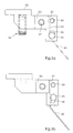
- 3A a preferred embodiment of a restraint knife 60 is shown that is fixed is connected to the lever 50 which is biased by a spring 53 around the pin 27.
- the restraint knife 60 has a curved support extension 62 at one end is held between a retaining pin 54 and a support surface 57. At the other end of the Extension 62, the retention knife 60 is held by a releasable pin 55 which fits exactly into a slot 56 of the lever 50. If the detachable pin 55 in the in Fig.
- the restraint knife 60 can run through a recess 90 in the support strip 11, as shown in Fig. 1.
- the retention knife 60 is preferably removable for easy replacement arranged as shown in Fig. 3B.
- the releasable pin 55 can be in the slot 56 a Release position in which the restraint knife 60 is moved down along the Support surface 57 and can be moved away from the holding pin 54 and removed.
- the present invention thus enables an exact height and Angle adjustment of the restraint knife 60 during the operation of the feed device.
- Setting scales 95, 96 may be provided.
- the restraint 20 can of course be substantially like that Restraint device 10 may be constructed. By loosening the bolts 13, the Retainers 10, 20 may be slidable along the front guide 5, such as is indicated by the arrow 92 in Fig. 1. To optimize their impact on the Printed products in the stack can position the retention members 10, 20 along the front section of the bow can be adjusted.
Landscapes
- Engineering & Computer Science (AREA)
- Mechanical Engineering (AREA)
- Sheets, Magazines, And Separation Thereof (AREA)
- Pile Receivers (AREA)
- Spinning Or Twisting Of Yarns (AREA)
- Container Filling Or Packaging Operations (AREA)
Applications Claiming Priority (2)
| Application Number | Priority Date | Filing Date | Title |
|---|---|---|---|
| US561468 | 1990-08-01 | ||
| US09/561,468 US6409164B1 (en) | 2000-04-28 | 2000-04-28 | Feeder pile restrictor and method |
Publications (3)
| Publication Number | Publication Date |
|---|---|
| EP1151945A2 true EP1151945A2 (fr) | 2001-11-07 |
| EP1151945A3 EP1151945A3 (fr) | 2003-07-23 |
| EP1151945B1 EP1151945B1 (fr) | 2005-09-07 |
Family
ID=24242098
Family Applications (1)
| Application Number | Title | Priority Date | Filing Date |
|---|---|---|---|
| EP01107413A Expired - Lifetime EP1151945B1 (fr) | 2000-04-28 | 2001-03-27 | Dispositif de retenue d'une pile de produits |
Country Status (5)
| Country | Link |
|---|---|
| US (1) | US6409164B1 (fr) |
| EP (1) | EP1151945B1 (fr) |
| JP (1) | JP2001315973A (fr) |
| AT (1) | ATE303965T1 (fr) |
| DE (2) | DE10114852A1 (fr) |
Family Cites Families (9)
| Publication number | Priority date | Publication date | Assignee | Title |
|---|---|---|---|---|
| US2251943A (en) | 1940-05-15 | 1941-08-12 | Tw & Cb Sheridan Co | Signature gathering machine |
| US2335064A (en) * | 1941-04-29 | 1943-11-23 | Borden Co | Sheet feeding apparatus |
| CH436350A (de) * | 1966-03-25 | 1967-05-31 | Mueller Hans Grapha Masch | Vorrichtung zum Trennen von Papierbogen |
| DE3001733A1 (de) * | 1980-01-18 | 1981-07-23 | Hauni-Werke Körber & Co KG, 2050 Hamburg | Vorrichtung zum auffuellen eines zuschnittmagazins mit kartonzuschnitten |
| US4456241A (en) * | 1982-08-12 | 1984-06-26 | Newsome John R | Sucker type card feeder |
| US5199699A (en) * | 1992-03-18 | 1993-04-06 | Videojet Systems International, Inc. | Base having anti-vibration means |
| JPH0592246U (ja) * | 1992-04-28 | 1993-12-17 | 株式会社三協精機製作所 | カ−ド送り出し装置 |
| DE4343146C2 (de) | 1993-03-12 | 2000-02-17 | Heidelberger Druckmasch Ag | Vorrichtung zum Vereinzeln von Papierprodukten, zum Beispiel Signaturen und Zeitungen von einem Stapel mittels einer rotierbar gelagerten Greifertrommel |
| US5641155A (en) * | 1995-06-07 | 1997-06-24 | Roberts Systems, Inc. | Compensating prefeeder gate and method |
-
2000
- 2000-04-28 US US09/561,468 patent/US6409164B1/en not_active Expired - Lifetime
-
2001
- 2001-03-26 DE DE10114852A patent/DE10114852A1/de not_active Withdrawn
- 2001-03-27 EP EP01107413A patent/EP1151945B1/fr not_active Expired - Lifetime
- 2001-03-27 DE DE50107328T patent/DE50107328D1/de not_active Expired - Lifetime
- 2001-03-27 AT AT01107413T patent/ATE303965T1/de not_active IP Right Cessation
- 2001-04-25 JP JP2001128229A patent/JP2001315973A/ja active Pending
Also Published As
| Publication number | Publication date |
|---|---|
| DE10114852A1 (de) | 2001-12-06 |
| ATE303965T1 (de) | 2005-09-15 |
| EP1151945A3 (fr) | 2003-07-23 |
| US6409164B1 (en) | 2002-06-25 |
| EP1151945B1 (fr) | 2005-09-07 |
| DE50107328D1 (de) | 2005-10-13 |
| JP2001315973A (ja) | 2001-11-13 |
Similar Documents
| Publication | Publication Date | Title |
|---|---|---|
| DE102014016630B4 (de) | Verstelleinrichtung für eine Druckrolle einer Bearbeitungsmaschine, insbesondere Kehlmaschine, sowie Bearbeitsmaschine, insbesondere Kehlmaschine, mit einer solchen Verstelleinrichtung | |
| DE1910977B2 (de) | Schraubstockvorrichtung, insbesondere für tragbare werkbänke | |
| DE3706058A1 (de) | Anleger fuer eine druckmaschine | |
| EP0254837B1 (fr) | Butée pour le bord arrière d'une feuille pour des réceptacles à feuilles | |
| DE2436155C2 (de) | Skibremse | |
| DE2137661B1 (de) | Seitenmarke zum seitlichen Aus richten eines Bogens auf dem Anlage tisch einer bogen verarbeitenden Maschine | |
| EP1151945B1 (fr) | Dispositif de retenue d'une pile de produits | |
| DE60115702T2 (de) | Ausziehführung | |
| DE102009031117B3 (de) | Vorrichtung und Verfahren zur stapelförmigen Ablage von bogenförmigen Substraten | |
| EP1238930A2 (fr) | Dispositif de séparation de feuilles | |
| DE102005055890B4 (de) | Vorrichtung mit Führungsflächen zur Ablage von Bögen für eine Druckmaschine | |
| DE202012001452U1 (de) | Lageverstellbare Schneidevorrichtung für Papierschneidemaschine | |
| DE10150416B4 (de) | Ausrichtungsvorrichtung zum Ausrichten von Eingabe/Ausgabevorrichtungen mit Druckern | |
| DE10244219B4 (de) | Vorrichtung und Verfahren zur Bogenzufuhr an eine Bogenverarbeitende Maschine, insbesondere Druckmaschine | |
| DE1761358A1 (de) | Vorrichtung an Druckmaschinen fuer das seitliche Ausrichten von Papierboegen | |
| DE9000255U1 (de) | Leiteinrichtung | |
| DE2502790C2 (de) | Rundstapelbogenanleger | |
| DE10127250A1 (de) | Vorrichtung zum Festlegen der Lage eines Bogens auf einem Anlagetisch | |
| DE10307135A1 (de) | Leitvorrichtung für einen Bogen im Anleger einer Bogen verarbeitenden Maschine, insbesondere Druckmaschine | |
| AT16843U1 (de) | Zubehörvorrichtung für ein elektronisches Markiergerät | |
| EP3192757B1 (fr) | Dispositif de dépôt pour produits plats | |
| DE1883031U (de) | Einstellbarer registeranschlag. | |
| EP2723535B1 (fr) | Support de reliure apte a etre utilise dans la reliure de livres, procede pour relier une liasse de feuilles et agencement d'appareil apte a etre utilise dans la reliure de livres | |
| DE102018217256B3 (de) | Bogenanleger | |
| DE10150300B4 (de) | Vorrichtung zur Bogenausrichtung in einer Bogendruckmaschine und zur Deckmarkenanordnung in selbiger |
Legal Events
| Date | Code | Title | Description |
|---|---|---|---|
| PUAI | Public reference made under article 153(3) epc to a published international application that has entered the european phase |
Free format text: ORIGINAL CODE: 0009012 |
|
| AK | Designated contracting states |
Kind code of ref document: A2 Designated state(s): AT BE CH CY DE DK ES FI FR GB GR IE IT LI LU MC NL PT SE TR |
|
| AX | Request for extension of the european patent |
Free format text: AL;LT;LV;MK;RO;SI |
|
| PUAL | Search report despatched |
Free format text: ORIGINAL CODE: 0009013 |
|
| AK | Designated contracting states |
Designated state(s): AT BE CH CY DE DK ES FI FR GB GR IE IT LI LU MC NL PT SE TR |
|
| AX | Request for extension of the european patent |
Extension state: AL LT LV MK RO SI |
|
| 17P | Request for examination filed |
Effective date: 20030625 |
|
| 17Q | First examination report despatched |
Effective date: 20031023 |
|
| AKX | Designation fees paid |
Designated state(s): AT BE CH CY DE DK ES FI FR GB GR IE IT LI LU MC NL PT SE TR |
|
| RAP1 | Party data changed (applicant data changed or rights of an application transferred) |
Owner name: GOSS INTERNATIONAL AMERICAS, INC. |
|
| GRAP | Despatch of communication of intention to grant a patent |
Free format text: ORIGINAL CODE: EPIDOSNIGR1 |
|
| RTI1 | Title (correction) |
Free format text: DEVICE FOR RETAINING A STACK OF PRODUCTS |
|
| GRAS | Grant fee paid |
Free format text: ORIGINAL CODE: EPIDOSNIGR3 |
|
| GRAA | (expected) grant |
Free format text: ORIGINAL CODE: 0009210 |
|
| AK | Designated contracting states |
Kind code of ref document: B1 Designated state(s): AT BE CH CY DE DK ES FI FR GB GR IE IT LI LU MC NL PT SE TR |
|
| PG25 | Lapsed in a contracting state [announced via postgrant information from national office to epo] |
Ref country code: IT Free format text: LAPSE BECAUSE OF FAILURE TO SUBMIT A TRANSLATION OF THE DESCRIPTION OR TO PAY THE FEE WITHIN THE PRESCRIBED TIME-LIMIT;WARNING: LAPSES OF ITALIAN PATENTS WITH EFFECTIVE DATE BEFORE 2007 MAY HAVE OCCURRED AT ANY TIME BEFORE 2007. THE CORRECT EFFECTIVE DATE MAY BE DIFFERENT FROM THE ONE RECORDED. Effective date: 20050907 Ref country code: FI Free format text: LAPSE BECAUSE OF FAILURE TO SUBMIT A TRANSLATION OF THE DESCRIPTION OR TO PAY THE FEE WITHIN THE PRESCRIBED TIME-LIMIT Effective date: 20050907 Ref country code: NL Free format text: LAPSE BECAUSE OF FAILURE TO SUBMIT A TRANSLATION OF THE DESCRIPTION OR TO PAY THE FEE WITHIN THE PRESCRIBED TIME-LIMIT Effective date: 20050907 Ref country code: GB Free format text: LAPSE BECAUSE OF FAILURE TO SUBMIT A TRANSLATION OF THE DESCRIPTION OR TO PAY THE FEE WITHIN THE PRESCRIBED TIME-LIMIT Effective date: 20050907 Ref country code: IE Free format text: LAPSE BECAUSE OF FAILURE TO SUBMIT A TRANSLATION OF THE DESCRIPTION OR TO PAY THE FEE WITHIN THE PRESCRIBED TIME-LIMIT Effective date: 20050907 |
|
| REG | Reference to a national code |
Ref country code: GB Ref legal event code: FG4D Free format text: NOT ENGLISH |
|
| REG | Reference to a national code |
Ref country code: CH Ref legal event code: EP |
|
| REG | Reference to a national code |
Ref country code: IE Ref legal event code: FG4D Free format text: LANGUAGE OF EP DOCUMENT: GERMAN |
|
| REF | Corresponds to: |
Ref document number: 50107328 Country of ref document: DE Date of ref document: 20051013 Kind code of ref document: P |
|
| PG25 | Lapsed in a contracting state [announced via postgrant information from national office to epo] |
Ref country code: DK Free format text: LAPSE BECAUSE OF FAILURE TO SUBMIT A TRANSLATION OF THE DESCRIPTION OR TO PAY THE FEE WITHIN THE PRESCRIBED TIME-LIMIT Effective date: 20051207 Ref country code: GR Free format text: LAPSE BECAUSE OF FAILURE TO SUBMIT A TRANSLATION OF THE DESCRIPTION OR TO PAY THE FEE WITHIN THE PRESCRIBED TIME-LIMIT Effective date: 20051207 Ref country code: SE Free format text: LAPSE BECAUSE OF FAILURE TO SUBMIT A TRANSLATION OF THE DESCRIPTION OR TO PAY THE FEE WITHIN THE PRESCRIBED TIME-LIMIT Effective date: 20051207 |
|
| REG | Reference to a national code |
Ref country code: CH Ref legal event code: NV Representative=s name: KIRKER & CIE SA |
|
| PG25 | Lapsed in a contracting state [announced via postgrant information from national office to epo] |
Ref country code: PT Free format text: LAPSE BECAUSE OF FAILURE TO SUBMIT A TRANSLATION OF THE DESCRIPTION OR TO PAY THE FEE WITHIN THE PRESCRIBED TIME-LIMIT Effective date: 20060207 |
|
| NLV1 | Nl: lapsed or annulled due to failure to fulfill the requirements of art. 29p and 29m of the patents act | ||
| PGFP | Annual fee paid to national office [announced via postgrant information from national office to epo] |
Ref country code: FR Payment date: 20060317 Year of fee payment: 6 |
|
| PG25 | Lapsed in a contracting state [announced via postgrant information from national office to epo] |
Ref country code: AT Free format text: LAPSE BECAUSE OF NON-PAYMENT OF DUE FEES Effective date: 20060327 |
|
| PG25 | Lapsed in a contracting state [announced via postgrant information from national office to epo] |
Ref country code: LU Free format text: LAPSE BECAUSE OF NON-PAYMENT OF DUE FEES Effective date: 20060331 Ref country code: MC Free format text: LAPSE BECAUSE OF NON-PAYMENT OF DUE FEES Effective date: 20060331 Ref country code: BE Free format text: LAPSE BECAUSE OF NON-PAYMENT OF DUE FEES Effective date: 20060331 |
|
| GBV | Gb: ep patent (uk) treated as always having been void in accordance with gb section 77(7)/1977 [no translation filed] |
Effective date: 20050907 |
|
| REG | Reference to a national code |
Ref country code: IE Ref legal event code: FD4D |
|
| PLBE | No opposition filed within time limit |
Free format text: ORIGINAL CODE: 0009261 |
|
| STAA | Information on the status of an ep patent application or granted ep patent |
Free format text: STATUS: NO OPPOSITION FILED WITHIN TIME LIMIT |
|
| 26N | No opposition filed |
Effective date: 20060608 |
|
| PG25 | Lapsed in a contracting state [announced via postgrant information from national office to epo] |
Ref country code: FR Free format text: LAPSE BECAUSE OF FAILURE TO SUBMIT A TRANSLATION OF THE DESCRIPTION OR TO PAY THE FEE WITHIN THE PRESCRIBED TIME-LIMIT Effective date: 20061020 |
|
| EN | Fr: translation not filed | ||
| BERE | Be: lapsed |
Owner name: GOSS INTERNATIONAL AMERICAS, INC. Effective date: 20060331 |
|
| PG25 | Lapsed in a contracting state [announced via postgrant information from national office to epo] |
Ref country code: TR Free format text: LAPSE BECAUSE OF FAILURE TO SUBMIT A TRANSLATION OF THE DESCRIPTION OR TO PAY THE FEE WITHIN THE PRESCRIBED TIME-LIMIT Effective date: 20050907 |
|
| PG25 | Lapsed in a contracting state [announced via postgrant information from national office to epo] |
Ref country code: CY Free format text: LAPSE BECAUSE OF FAILURE TO SUBMIT A TRANSLATION OF THE DESCRIPTION OR TO PAY THE FEE WITHIN THE PRESCRIBED TIME-LIMIT Effective date: 20050907 |
|
| PG25 | Lapsed in a contracting state [announced via postgrant information from national office to epo] |
Ref country code: ES Free format text: LAPSE BECAUSE OF NON-PAYMENT OF DUE FEES Effective date: 20060331 |
|
| PGFP | Annual fee paid to national office [announced via postgrant information from national office to epo] |
Ref country code: CH Payment date: 20110325 Year of fee payment: 11 |
|
| PGFP | Annual fee paid to national office [announced via postgrant information from national office to epo] |
Ref country code: DE Payment date: 20110329 Year of fee payment: 11 |
|
| REG | Reference to a national code |
Ref country code: CH Ref legal event code: PL |
|
| REG | Reference to a national code |
Ref country code: DE Ref legal event code: R119 Ref document number: 50107328 Country of ref document: DE Effective date: 20121002 |
|
| PG25 | Lapsed in a contracting state [announced via postgrant information from national office to epo] |
Ref country code: LI Free format text: LAPSE BECAUSE OF NON-PAYMENT OF DUE FEES Effective date: 20120331 Ref country code: CH Free format text: LAPSE BECAUSE OF NON-PAYMENT OF DUE FEES Effective date: 20120331 |
|
| PG25 | Lapsed in a contracting state [announced via postgrant information from national office to epo] |
Ref country code: DE Free format text: LAPSE BECAUSE OF NON-PAYMENT OF DUE FEES Effective date: 20121002 |