EP1152152A2 - Dispositif de positionnement pour élément détecteur d'un petit ventilateur - Google Patents
Dispositif de positionnement pour élément détecteur d'un petit ventilateur Download PDFInfo
- Publication number
- EP1152152A2 EP1152152A2 EP00119633A EP00119633A EP1152152A2 EP 1152152 A2 EP1152152 A2 EP 1152152A2 EP 00119633 A EP00119633 A EP 00119633A EP 00119633 A EP00119633 A EP 00119633A EP 1152152 A2 EP1152152 A2 EP 1152152A2
- Authority
- EP
- European Patent Office
- Prior art keywords
- sensor element
- positioning device
- miniature fan
- pole
- circuit board
- Prior art date
- Legal status (The legal status is an assumption and is not a legal conclusion. Google has not performed a legal analysis and makes no representation as to the accuracy of the status listed.)
- Withdrawn
Links
- 238000004804 winding Methods 0.000 claims description 5
- 238000003780 insertion Methods 0.000 claims description 4
- 230000037431 insertion Effects 0.000 claims description 4
- 230000000694 effects Effects 0.000 description 4
- 238000012986 modification Methods 0.000 description 2
- 230000004048 modification Effects 0.000 description 2
- 238000001514 detection method Methods 0.000 description 1
Images


Classifications
-
- F—MECHANICAL ENGINEERING; LIGHTING; HEATING; WEAPONS; BLASTING
- F04—POSITIVE - DISPLACEMENT MACHINES FOR LIQUIDS; PUMPS FOR LIQUIDS OR ELASTIC FLUIDS
- F04D—NON-POSITIVE-DISPLACEMENT PUMPS
- F04D25/00—Pumping installations or systems
- F04D25/02—Units comprising pumps and their driving means
- F04D25/08—Units comprising pumps and their driving means the working fluid being air, e.g. for ventilation
-
- F—MECHANICAL ENGINEERING; LIGHTING; HEATING; WEAPONS; BLASTING
- F04—POSITIVE - DISPLACEMENT MACHINES FOR LIQUIDS; PUMPS FOR LIQUIDS OR ELASTIC FLUIDS
- F04D—NON-POSITIVE-DISPLACEMENT PUMPS
- F04D29/00—Details, component parts, or accessories
- F04D29/60—Mounting; Assembling; Disassembling
- F04D29/64—Mounting; Assembling; Disassembling of axial pumps
- F04D29/644—Mounting; Assembling; Disassembling of axial pumps especially adapted for elastic fluid pumps
- F04D29/646—Mounting or removal of fans
-
- H—ELECTRICITY
- H02—GENERATION; CONVERSION OR DISTRIBUTION OF ELECTRIC POWER
- H02K—DYNAMO-ELECTRIC MACHINES
- H02K29/00—Motors or generators having non-mechanical commutating devices, e.g. discharge tubes or semiconductor devices
- H02K29/06—Motors or generators having non-mechanical commutating devices, e.g. discharge tubes or semiconductor devices with position sensing devices
Definitions
- the present invention relates to a positioning device for a sensor element of a miniature fan, and more particularly to a positioning device for positioning a sensor element of a miniature fan to minimize thickness of the miniature fan and to locate the sensor element in an optimal position for detection.
- a sensor element for detecting polarity of the rotor of a miniature fan, thereby sending signals to change polarity of the stator winding for providing alternating magnetic fields.
- the miniature fan may retain the best operational quality if the sensor element can be located in the optimal position relative to the stator magnetic poles.
- U.S. Patent No. 5,967,763 issued to Horng on Oct. 19, 1999 disclose optimal positioning devices for a sensor element of a miniature fan, wherein the sensor element mounted on a circuit board is located on a vertical line extending from one of the first end edge and the second end edge of one of the poles of the coil seat.
- Miniaturization is a trend in miniature fans.
- the above-mentioned positioning devices may provide required positioning effect for the sensor element for providing improved operational effect, but the overall thickness of the resultant miniature fan cannot be further reduced.
- the thickness of the miniature fan is further reduced, the positioning uniformity for the sensor element relative to front end edge or rear end edge of magnetic poles of the stator becomes relatively difficult.
- the quality of the produced miniature fans is more consistent.
- a positioning device in accordance with the present invention includes an axle tube for engaging with a circuit board and a stator.
- the circuit board includes control elements and a sensor element thereon.
- Each pole of the stator includes two pole ends.
- a gap exists between two adjacent pole ends respectively of two adjacent poles. The gap receives the sensor element or provides a positioning reference for the sensor element.
- a first embodiment of a positioning device for a sensor element of a miniature fan in accordance with the present invention generally includes a circuit board 1 and a stator 2.
- the circuit board 1 may be of any conventional structure and includes necessary control elements 11.
- An axle tube 10 is provided on the circuit board 1.
- the axle tube 10 may be a tube that extends through a central hole (not shown) of the circuit board 1 or an axle tube formed on a housing (not shown) of a miniature fan (not shown).
- the axle tube 10 provides engagement for the circuit board 1 and the stator 2 and supports a shaft of a rotor for rotation.
- the circuit board 1 further includes a sensor element 12 that is upright in this embodiment.
- the stator 2 may be of any conventional structure.
- the stator 2 includes radial windings and includes four poles each having two pole ends 21 and 22. In two adjacent poles, the pole end 21 of one pole and the pole end 22 of the other pole have a gap 23 therebetween.
- the gap 23 has a width that is slightly greater than that of the sensor element 12, thereby allowing insertion of the sensor element 12 into the gap 23.
- Fig. 2 illustrates assembly of the first embodiment of the positioning device in accordance with the present invention, wherein the sensor element 12 on the circuit board 1 is aligned with the gap 23 between two adjacent poles ends respectively of two adjacent poles.
- the sensor element 12 may be inserted into the gap 23, such that the overall thickness for the circuit board 1 and the stator 2 is minimized after assembly.
- Figs. 3 and 4 illustrate a second embodiment of the positioning device in accordance with the present invention that is substantially identical to the first embodiment.
- the sensor element 12 in the second embodiment lies horizontally to further minimize the overall thickness for the circuit board 1 and the stator 2 after assembly.
- relative position for the stator poles and the sensor element 12 is more consistent so as to retain the sensor element 12 in the optimal detecting position.
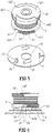
- Figs. 5 and 6 illustrate a third embodiment of the positioning device in accordance with the present invention.
- the positioning device includes a circuit board 3 and a stator 4.
- the circuit board 3 includes an axle hole 30 through which an axle tube 41 on the stator 4 extends.
- the circuit board 3 includes conventional control elements 31 and a sensor element 32. If necessary, the circuit board 3 may include a notch 33 to allow insertion of the sensor element 32, thereby further minimizing the overall thickness after assembly.
- the stator 4 in this embodiment is a stator having axial windings.
- the stator 4 includes an upper pole plate 42 and a lower pole plate 43 that are located on different planes.
- the axle tube 41 is used to engage with the circuit board 3, the upper pole plate 42, and the lower pole plate 43. However, the axle tube 41 may be directly formed on a housing (not shown) of a miniature fan (not shown).
- the upper pole plate 42 includes two poles each having two pole ends 421 and 422.
- the lower pole plate 43 includes two poles each having two pole ends 431 and 432. The pole ends 421 and 422 of the upper pole plate 42 are misaligned with the pole ends 431 and 432 of the lower pole plate 42.
- a gap 44 is defined in a vertical direction between the pole end 421 of the upper pole plate 42 and the pole end 432 of the lower pole plate 43.
- the gap 44 provides an alignment reference for the sensor element 32. If necessary, the sensor element 32 may be inserted into the gap 44 to further minimize the overall thickness after assembly.
- the senor element can be easily fixed in an optimal detecting position relative to the stator poles by providing the positioning devices in accordance with the present invention, thereby providing consistent operational effect for the miniature fans so constructed.
- the miniature fans so constructed have a minimized thickness.
Landscapes
- Engineering & Computer Science (AREA)
- Mechanical Engineering (AREA)
- General Engineering & Computer Science (AREA)
- Power Engineering (AREA)
Applications Claiming Priority (2)
| Application Number | Priority Date | Filing Date | Title |
|---|---|---|---|
| US09/563,954 US6407473B1 (en) | 2000-05-02 | 2000-05-02 | Positioning device for a sensor element of a miniature fan |
| US563954 | 2000-05-02 |
Publications (2)
| Publication Number | Publication Date |
|---|---|
| EP1152152A2 true EP1152152A2 (fr) | 2001-11-07 |
| EP1152152A3 EP1152152A3 (fr) | 2003-01-08 |
Family
ID=24252581
Family Applications (1)
| Application Number | Title | Priority Date | Filing Date |
|---|---|---|---|
| EP00119633A Withdrawn EP1152152A3 (fr) | 2000-05-02 | 2000-09-08 | Dispositif de positionnement pour élément détecteur d'un petit ventilateur |
Country Status (2)
| Country | Link |
|---|---|
| US (1) | US6407473B1 (fr) |
| EP (1) | EP1152152A3 (fr) |
Families Citing this family (9)
| Publication number | Priority date | Publication date | Assignee | Title |
|---|---|---|---|---|
| JP3790442B2 (ja) * | 2001-05-29 | 2006-06-28 | 建準電機工業股▲分▼有限公司 | 半径方向巻線のステータ装置 |
| US6756718B2 (en) * | 2001-06-08 | 2004-06-29 | Bill Lee | Positioning structure for air fan induction element and stator |
| GB2401996A (en) * | 2003-04-04 | 2004-11-24 | Sunonwealth Electr Mach Ind Co | Stator construction for a reduced thickness brushless DC motor |
| TWI276281B (en) * | 2004-06-23 | 2007-03-11 | Delta Electronics Inc | Stator structure of motor |
| CN101826783B (zh) * | 2009-03-05 | 2011-09-14 | 中山大洋电机股份有限公司 | 一种用于感应转子位置的感应装置 |
| KR101655161B1 (ko) * | 2014-11-24 | 2016-09-07 | 현대자동차 주식회사 | 계자권선형 구동모터의 회전자 |
| US11870308B2 (en) * | 2019-11-15 | 2024-01-09 | Borgwarner Inc. | System of radially inserting a thermistor into a stator core |
| CN115681181A (zh) * | 2022-09-27 | 2023-02-03 | 太仓市华盈电子材料有限公司 | 一种风扇结构 |
| CN218542660U (zh) * | 2022-11-15 | 2023-02-28 | 台达电子工业股份有限公司 | 风扇模块 |
Family Cites Families (21)
| Publication number | Priority date | Publication date | Assignee | Title |
|---|---|---|---|---|
| DE2835210C2 (de) | 1978-08-11 | 1988-03-24 | Papst-Motoren GmbH & Co KG, 7742 St Georgen | Zweipulsiger, zweisträngiger Kollektorloser Gleichstrommotor mit einem mindestens vierpoligen permanentmagnetischen Rotor |
| US4547714A (en) | 1978-08-11 | 1985-10-15 | Papst-Motoren Gmbh & Co. Kg | Low magnetic leakage flux brushless pulse controlled d-c motor |
| US4554491A (en) * | 1984-08-10 | 1985-11-19 | Msl Industries, Inc. | Brushless DC motor having a laminated stator with a single stator winding |
| JPS62203542A (ja) * | 1986-03-04 | 1987-09-08 | Shinano Kenshi Kk | 2相直流ブラシレスモ−タ |
| EP0259724B1 (fr) * | 1986-09-12 | 1990-11-22 | Siemens Aktiengesellschaft | Plaque à conducteurs |
| US4934041A (en) * | 1988-07-27 | 1990-06-19 | Nidec Corporation | Method of assembling brushless electric motors |
| CA2037852C (fr) * | 1991-02-26 | 1993-06-29 | Alex Horng | Moteur a courant continu, sans balais, avec stator en plastique |
| GB2269058B (en) * | 1992-07-27 | 1996-03-06 | Alex Horng | Industrial heat dissipating electric fan |
| US5600192A (en) * | 1994-07-29 | 1997-02-04 | Sorvall Products, L.P. | DC electric motor having a flux concentrating member thereon |
| US5539263A (en) * | 1994-09-27 | 1996-07-23 | Lee; Tzu-I | Direct current driving ventilation fan |
| TW404620U (en) * | 1996-11-25 | 2000-09-01 | Ind Tech Res Inst | Brush-less motor stator |
| US5986379A (en) * | 1996-12-05 | 1999-11-16 | General Electric Company | Motor with external rotor |
| US5859487A (en) * | 1997-05-30 | 1999-01-12 | Delta Electronics, Inc. | Stator structure of motor and its forming method |
| US5917262A (en) * | 1997-06-17 | 1999-06-29 | Industrial Technology Research Institute | Stator structure for miniaturized DC brushless motor |
| US6114785A (en) * | 1997-10-21 | 2000-09-05 | Sunonwealth Electric Machine Industry Co., Ltd. | Positioning device for a sensor element of a miniature fan |
| US6109892A (en) | 1997-10-21 | 2000-08-29 | Sunonwealth Electric Machine Industry Co., Ltd. | Positioning device for a sensor element of a miniature fan |
| US5967763A (en) | 1997-10-21 | 1999-10-19 | Horng; Ching-Shen | Positioning devices for a sensor element of a miniature fan |
| US5962938A (en) * | 1997-10-21 | 1999-10-05 | General Electric Company | Motor with external rotor |
| DE29719350U1 (de) * | 1997-10-31 | 1998-01-15 | Horng, Ching-Shen, Kaohsiung | Positionierungseinrichtung für ein Sensorelement eines Miniaturgebläses |
| TW345346U (en) * | 1997-12-09 | 1998-11-11 | Sunonwealth Electr Mach Ind Co | Improved structure for radiator fan motor |
| US6050785A (en) * | 1998-11-04 | 2000-04-18 | Sunonwealth Electric Machine Industry Co., Ltd. | Axle balance plates for miniature heat dissipating fan assemblies |
-
2000
- 2000-05-02 US US09/563,954 patent/US6407473B1/en not_active Expired - Fee Related
- 2000-09-08 EP EP00119633A patent/EP1152152A3/fr not_active Withdrawn
Also Published As
| Publication number | Publication date |
|---|---|
| US6407473B1 (en) | 2002-06-18 |
| EP1152152A3 (fr) | 2003-01-08 |
| US20020047345A1 (en) | 2002-04-25 |
Similar Documents
| Publication | Publication Date | Title |
|---|---|---|
| US6525938B1 (en) | Circuit board fixing structure of heatsink fan | |
| US6400053B1 (en) | Axle balance plates for D.C brushless motor | |
| US10305358B2 (en) | Low cost limited rotation rotary actuator | |
| US6465921B1 (en) | Assembling structure of a miniature vibration motor | |
| US6565326B2 (en) | Heat-dissipating fan structure | |
| US20070267927A1 (en) | Balancing structure for motor | |
| US6608411B2 (en) | Direct current brushless motor | |
| US6407473B1 (en) | Positioning device for a sensor element of a miniature fan | |
| US5045740A (en) | Brushless motor | |
| US4958099A (en) | Brushless motor | |
| US5967763A (en) | Positioning devices for a sensor element of a miniature fan | |
| EP0855787B1 (fr) | Moteur à courant continu comprenant un détecteur de rotation | |
| US10720824B2 (en) | Low cost limited rotation rotary actuator | |
| US8063529B2 (en) | Motor | |
| JPH10313565A (ja) | 小型モータ | |
| JP3384180B2 (ja) | モータ | |
| US20020149285A1 (en) | Brushless DC motor with axial winding/axial air gap | |
| US6809457B1 (en) | Brushless DC motor with a reduced thickness | |
| JP3046048B2 (ja) | ブラシレスモータ | |
| US20020149284A1 (en) | Stator assembly structure of a direct current brushless motor | |
| KR100524100B1 (ko) | 열 방산형 팬 구조 | |
| JPH07123672A (ja) | モータ | |
| JPH0332349A (ja) | 無刷子電動機 | |
| GB2374207A (en) | Stator assembly structure of a direct current brushless motor | |
| JPS58130762A (ja) | 直流ブラシレスモ−タ |
Legal Events
| Date | Code | Title | Description |
|---|---|---|---|
| PUAI | Public reference made under article 153(3) epc to a published international application that has entered the european phase |
Free format text: ORIGINAL CODE: 0009012 |
|
| AK | Designated contracting states |
Kind code of ref document: A2 Designated state(s): AT BE CH CY DE DK ES FI FR GB GR IE IT LI LU MC NL PT SE |
|
| AX | Request for extension of the european patent |
Free format text: AL;LT;LV;MK;RO;SI |
|
| PUAL | Search report despatched |
Free format text: ORIGINAL CODE: 0009013 |
|
| AK | Designated contracting states |
Kind code of ref document: A3 Designated state(s): AT BE CH CY DE DK ES FI FR GB GR IE IT LI LU MC NL PT SE |
|
| AX | Request for extension of the european patent |
Free format text: AL;LT;LV;MK;RO;SI |
|
| STAA | Information on the status of an ep patent application or granted ep patent |
Free format text: STATUS: THE APPLICATION IS DEEMED TO BE WITHDRAWN |
|
| AKX | Designation fees paid | ||
| 18D | Application deemed to be withdrawn |
Effective date: 20030401 |
|
| REG | Reference to a national code |
Ref country code: DE Ref legal event code: 8566 |