EP1152200A1 - Kühlschrank - Google Patents
Kühlschrank Download PDFInfo
- Publication number
- EP1152200A1 EP1152200A1 EP01810389A EP01810389A EP1152200A1 EP 1152200 A1 EP1152200 A1 EP 1152200A1 EP 01810389 A EP01810389 A EP 01810389A EP 01810389 A EP01810389 A EP 01810389A EP 1152200 A1 EP1152200 A1 EP 1152200A1
- Authority
- EP
- European Patent Office
- Prior art keywords
- compartment
- special
- cooling
- air
- heat exchanger
- Prior art date
- Legal status (The legal status is an assumption and is not a legal conclusion. Google has not performed a legal analysis and makes no representation as to the accuracy of the status listed.)
- Granted
Links
Images


Classifications
-
- F—MECHANICAL ENGINEERING; LIGHTING; HEATING; WEAPONS; BLASTING
- F25—REFRIGERATION OR COOLING; COMBINED HEATING AND REFRIGERATION SYSTEMS; HEAT PUMP SYSTEMS; MANUFACTURE OR STORAGE OF ICE; LIQUEFACTION SOLIDIFICATION OF GASES
- F25D—REFRIGERATORS; COLD ROOMS; ICE-BOXES; COOLING OR FREEZING APPARATUS NOT OTHERWISE PROVIDED FOR
- F25D17/00—Arrangements for circulating cooling fluids; Arrangements for circulating gas, e.g. air, within refrigerated spaces
- F25D17/04—Arrangements for circulating cooling fluids; Arrangements for circulating gas, e.g. air, within refrigerated spaces for circulating air, e.g. by convection
- F25D17/06—Arrangements for circulating cooling fluids; Arrangements for circulating gas, e.g. air, within refrigerated spaces for circulating air, e.g. by convection by forced circulation
- F25D17/062—Arrangements for circulating cooling fluids; Arrangements for circulating gas, e.g. air, within refrigerated spaces for circulating air, e.g. by convection by forced circulation in household refrigerators
- F25D17/065—Arrangements for circulating cooling fluids; Arrangements for circulating gas, e.g. air, within refrigerated spaces for circulating air, e.g. by convection by forced circulation in household refrigerators with compartments at different temperatures
-
- F—MECHANICAL ENGINEERING; LIGHTING; HEATING; WEAPONS; BLASTING
- F25—REFRIGERATION OR COOLING; COMBINED HEATING AND REFRIGERATION SYSTEMS; HEAT PUMP SYSTEMS; MANUFACTURE OR STORAGE OF ICE; LIQUEFACTION SOLIDIFICATION OF GASES
- F25D—REFRIGERATORS; COLD ROOMS; ICE-BOXES; COOLING OR FREEZING APPARATUS NOT OTHERWISE PROVIDED FOR
- F25D11/00—Self-contained movable devices, e.g. domestic refrigerators
- F25D11/02—Self-contained movable devices, e.g. domestic refrigerators with cooling compartments at different temperatures
- F25D11/022—Self-contained movable devices, e.g. domestic refrigerators with cooling compartments at different temperatures with two or more evaporators
-
- F—MECHANICAL ENGINEERING; LIGHTING; HEATING; WEAPONS; BLASTING
- F25—REFRIGERATION OR COOLING; COMBINED HEATING AND REFRIGERATION SYSTEMS; HEAT PUMP SYSTEMS; MANUFACTURE OR STORAGE OF ICE; LIQUEFACTION SOLIDIFICATION OF GASES
- F25D—REFRIGERATORS; COLD ROOMS; ICE-BOXES; COOLING OR FREEZING APPARATUS NOT OTHERWISE PROVIDED FOR
- F25D2317/00—Details or arrangements for circulating cooling fluids; Details or arrangements for circulating gas, e.g. air, within refrigerated spaces, not provided for in other groups of this subclass
- F25D2317/06—Details or arrangements for circulating cooling fluids; Details or arrangements for circulating gas, e.g. air, within refrigerated spaces, not provided for in other groups of this subclass with forced air circulation
- F25D2317/061—Details or arrangements for circulating cooling fluids; Details or arrangements for circulating gas, e.g. air, within refrigerated spaces, not provided for in other groups of this subclass with forced air circulation through special compartments
-
- F—MECHANICAL ENGINEERING; LIGHTING; HEATING; WEAPONS; BLASTING
- F25—REFRIGERATION OR COOLING; COMBINED HEATING AND REFRIGERATION SYSTEMS; HEAT PUMP SYSTEMS; MANUFACTURE OR STORAGE OF ICE; LIQUEFACTION SOLIDIFICATION OF GASES
- F25D—REFRIGERATORS; COLD ROOMS; ICE-BOXES; COOLING OR FREEZING APPARATUS NOT OTHERWISE PROVIDED FOR
- F25D2317/00—Details or arrangements for circulating cooling fluids; Details or arrangements for circulating gas, e.g. air, within refrigerated spaces, not provided for in other groups of this subclass
- F25D2317/06—Details or arrangements for circulating cooling fluids; Details or arrangements for circulating gas, e.g. air, within refrigerated spaces, not provided for in other groups of this subclass with forced air circulation
- F25D2317/068—Details or arrangements for circulating cooling fluids; Details or arrangements for circulating gas, e.g. air, within refrigerated spaces, not provided for in other groups of this subclass with forced air circulation characterised by the fans
- F25D2317/0682—Two or more fans
-
- F—MECHANICAL ENGINEERING; LIGHTING; HEATING; WEAPONS; BLASTING
- F25—REFRIGERATION OR COOLING; COMBINED HEATING AND REFRIGERATION SYSTEMS; HEAT PUMP SYSTEMS; MANUFACTURE OR STORAGE OF ICE; LIQUEFACTION SOLIDIFICATION OF GASES
- F25D—REFRIGERATORS; COLD ROOMS; ICE-BOXES; COOLING OR FREEZING APPARATUS NOT OTHERWISE PROVIDED FOR
- F25D2400/00—General features of, or devices for refrigerators, cold rooms, ice-boxes, or for cooling or freezing apparatus not covered by any other subclass
- F25D2400/04—Refrigerators with a horizontal mullion
-
- F—MECHANICAL ENGINEERING; LIGHTING; HEATING; WEAPONS; BLASTING
- F25—REFRIGERATION OR COOLING; COMBINED HEATING AND REFRIGERATION SYSTEMS; HEAT PUMP SYSTEMS; MANUFACTURE OR STORAGE OF ICE; LIQUEFACTION SOLIDIFICATION OF GASES
- F25D—REFRIGERATORS; COLD ROOMS; ICE-BOXES; COOLING OR FREEZING APPARATUS NOT OTHERWISE PROVIDED FOR
- F25D2700/00—Means for sensing or measuring; Sensors therefor
- F25D2700/12—Sensors measuring the inside temperature
- F25D2700/121—Sensors measuring the inside temperature of particular compartments
-
- F—MECHANICAL ENGINEERING; LIGHTING; HEATING; WEAPONS; BLASTING
- F25—REFRIGERATION OR COOLING; COMBINED HEATING AND REFRIGERATION SYSTEMS; HEAT PUMP SYSTEMS; MANUFACTURE OR STORAGE OF ICE; LIQUEFACTION SOLIDIFICATION OF GASES
- F25D—REFRIGERATORS; COLD ROOMS; ICE-BOXES; COOLING OR FREEZING APPARATUS NOT OTHERWISE PROVIDED FOR
- F25D2700/00—Means for sensing or measuring; Sensors therefor
- F25D2700/12—Sensors measuring the inside temperature
- F25D2700/122—Sensors measuring the inside temperature of freezer compartments
Definitions
- the invention relates to a refrigerator with several superimposed Cooling zones, with a freezer compartment and one arranged above it Special subject.
- Such refrigerators are used in the household to keep food at different Store temperatures. Be in a freezer frozen food stored, a special compartment above with a temperature of around 0 ° C is used to ingest fish, meat, Vegetables - such as cucumbers, fruits or the like - and a third top cooling compartment with around 5 ° C to 11 ° C is used for the refrigerated storage of beverages and other foods.
- the object of the invention is to achieve a refrigerator to create less effort and reduced energy consumption.
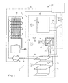
- Fig. 1 shows a schematic representation of a refrigerator cooling unit 1 with a design that is customary in household refrigerators.
- the refrigerator contains three cooling zones A, B, C, in which different Temperatures are maintained.
- the lowest cooling compartment A is designed as a freezer compartment with a temperature of around -18 ° C (to -24 ° C).
- the adjacent middle special compartment B above is for one Temperature of about 0 ° C (to + 5 ° C) and the top cooling compartment C is operated at a temperature above + 5 ° C (up to + 11 ° C).
- the cooling unit contains a conventional compressor 6, of which Coolant vapor is drawn in from the evaporators 10, 12 via a line 8 and is compressed to saturation pressure.
- a capacitor 14 if the steam is liquefied while removing heat, then via a the frame heater 16 associated with the freezer through lines 18, 32 fed to the evaporators 10, 12, the evaporator 12 in the refrigerator compartment C is connected to the freezer compartment A by means of coolant lines 32.
- the central special compartment B is only cooled through a cooling air flow extracted from the freezer compartment A, for this purpose between freezer compartment A and the special compartment arranged above it B Air circulation means for cooling the special compartment B are available.
- the air circulation means are designed such that a first air circulation from freezer compartment A to a heat exchanger 20 and a second one, is provided in the special compartment B from the first separate air circulation, which also interacts with the heat exchanger 20.
- Fig. 2 and Fig. 3 is for the first air circulation the rear wall of the refrigerator 1, behind the freezer compartment A and the special compartment B located air duct 25.
- This air duct 25 is by means of a first, in the area of the freezer compartment A arranged fan 26 cooling air from this Compartment A to heat exchanger 20 at special compartment B and back into that Freezer compartment A is directed.
- the air duct 25 points accordingly on the one hand an intake port 24 emanating from the fan 26, a horizontal containing the fins 21 of the heat exchanger 20 Piece and a return pipe 28 on.
- the heat exchanger 20 arranged at the rear wall of the special compartment B. consists of several horizontal in the air duct 25 Slats 21, an intermediate wall 23 and of itself in the special compartment B vertical slats 22. Take the horizontal slats 21 the coldness of the cold air circulating on these, with the air at approximately minus 18 ° C and cooled accordingly become.
- the intermediate wall 23 is used for the transmission of the generated Cold of the slats 21 of the channel on the slats 22 in special compartment B.
- the heat exchanger 20 is expediently made of a highly conductive material Material made, for example, from an aluminum die-cast.
- a separate air duct 35 formed by an approximately parallel to the rear wall 37 arranged aperture 36 is limited.
- a fan 30 driven by a motor 34 and below this arranged the vertically extending slats 22. Openings 38 are provided at the upper and lower ends of this channel 35, through this the air is sucked out of special compartment B and cooled Condition is directed back into this refrigerator compartment.
- the electrical control and display takes place centrally from a control panel 34 out. From this lines 36 go to the fans 26, 30, Lines 44, 46 to the temperature sensors 38, 39 in the cold rooms B, C and a line 48 to the compressor 6. Another, not shown Cable could also lead to a sensor in freezer compartment A.
- FIG. 4 An embodiment variant according to Figure 4 is that in the coolant line then a valve 40 is installed on the frame heater 16 which is a coolant line 42 directly to the evaporator 12 of the refrigerator compartment C connects. This enables "economy mode", for example, if the refrigerator is in a holiday home that is not used all the time is installed.
Landscapes
- Engineering & Computer Science (AREA)
- Chemical & Material Sciences (AREA)
- Combustion & Propulsion (AREA)
- Physics & Mathematics (AREA)
- Mechanical Engineering (AREA)
- Thermal Sciences (AREA)
- General Engineering & Computer Science (AREA)
- Devices That Are Associated With Refrigeration Equipment (AREA)
- Cold Air Circulating Systems And Constructional Details In Refrigerators (AREA)
- Lubrication Of Internal Combustion Engines (AREA)
- Acyclic And Carbocyclic Compounds In Medicinal Compositions (AREA)
- Valve Device For Special Equipments (AREA)
Abstract
Description
- Fig. 1
- ein Schema zu dem Kältekreislauf eines erfindungsgemässen Kühlschrankes,
- Fig.2
- eine Ansicht des Kühlschrankes von der Vorderseite bei geöffneter Türe, wobei die an sich unsichtbaren erfindungsgemässen Luftzirkulationsmittel mit durchgehenden Linien gezeichnet sind,
- Fig.3
- einen teilweisen Schnitt des Kühlschrankes entlang der Linie III-III nach Fig.2 in vergrösserter Darstellung, und
- Fig.4
- ein Schema einer Ausführungsvariante eines Kältekreislaufes.
Claims (6)
- Kühlschrank mit mehreren übereinander liegenden Kühlzonen, mit einem Tiefkühlfach (A) und einem getrennt zu diesem angeordneten Sonderfach (B), dadurch gekennzeichnet, dass zur Kühlung des Sonderfaches (B) zwischen dem Tiefkühlfach (A) und dem getrennt zu diesem angeordneten Sonderfach (B) Luftzirkulationsmittel (20, 24, 25, 26, 28, 30) vorhanden sind.
- Kühlschrank nach Anspruch 1, dadurch gekennzeichnet, dass die Luftzirkulationsmittel derart ausgestaltet sind, dass sie eine erste Luftzirkulation vom Tiefkühlfach (A) zu einem Wärmetauscher (20) und eine zweite, von dieser ersten getrennte Luftzirkulation im Sonderfach (B) bewirken, wobei letztere ebenfalls mit dem Wärmetauscher (20) zusammenwirkt.
- Kühlschrank nach Anspruch 2, dadurch gekennzeichnet, dass ein Luftführungskanal (25) vorhanden ist, durch den mittels eines ersten Ventilators (26) Kühlluft aus dem Tiefkühlfach (A) zum Wärmetauscher (20) beim Sonderfach (B) und zurück in das Tiefkühlfach (A) leitbar ist.
- Kühlschrank nach Anspruch 3, dadurch gekennzeichnet, dass der bei der Rückwand des Sonderfaches (B) angeordnete Wärmetauscher (20) im Luftführungskanal (25) befindliche horizontalen Lamellen (21) und durch eine Zwischenwand (23) von diesen räumlich getrennte vertikale Lamellen (22) aufweist, die sich in das Sonderfach (B) erstrecken, wobei die Zwischenwand (23) für die Übertragung der Kälte vom Luftführungskanal (25) in das Sonderfach (B) ausgelegt ist.
- Kühlschrank nach Anspruch 2, dadurch gekennzeichnet, dass in dem innenseitig zur Rückwand (37) dieses Sonderfaches (B) angeordneten Luftführungskanal (25) ein Ventilator (30) und unterhalb diesem die sich vertikal erstreckenden Lamellen (22) vorhanden sind, wobei am oberen und unteren Ende dieses Kanales (35) Öffnungen (38) vorgesehen sind, durch diese die Luft aus dem Sonderfach (B) angesaugt und in abgekühltem Zustand wieder zurück in diesen Kühlfachraum geleitet wird.
- Kühlschrank nach einem der vorhergehenden Ansprüche, dadurch gekennzeichnet, dass ein elektrisch steuerbares Ventil (40) vorhanden ist, mittels dem eine Zufuhr von Kältemittel vom Kondensator (14) entweder zu einem weiteren Kühlfach (C) und von diesem in das Tiefkühlfach (A) oder direkt zum Kühlfach (A) geleitet wird.
Applications Claiming Priority (2)
| Application Number | Priority Date | Filing Date | Title |
|---|---|---|---|
| CH877002000 | 2000-05-04 | ||
| CH00877/00A CH694472A5 (de) | 2000-05-04 | 2000-05-04 | Kühlschrank. |
Publications (2)
| Publication Number | Publication Date |
|---|---|
| EP1152200A1 true EP1152200A1 (de) | 2001-11-07 |
| EP1152200B1 EP1152200B1 (de) | 2007-09-05 |
Family
ID=4544507
Family Applications (1)
| Application Number | Title | Priority Date | Filing Date |
|---|---|---|---|
| EP01810389A Expired - Lifetime EP1152200B1 (de) | 2000-05-04 | 2001-04-23 | Kühlschrank |
Country Status (4)
| Country | Link |
|---|---|
| EP (1) | EP1152200B1 (de) |
| AT (1) | ATE372491T1 (de) |
| CH (1) | CH694472A5 (de) |
| DE (1) | DE50112944D1 (de) |
Citations (7)
| Publication number | Priority date | Publication date | Assignee | Title |
|---|---|---|---|---|
| US3633375A (en) * | 1970-04-15 | 1972-01-11 | Westinghouse Electric Corp | Refrigerator cooling system design |
| US3834180A (en) * | 1972-12-29 | 1974-09-10 | Umc Ind | Heat exchange unit |
| EP0326049A1 (de) * | 1988-01-29 | 1989-08-02 | INDUSTRIE ZANUSSI S.p.A. | Kühlvorrichtung für mehrere Temperaturen mit einem Einkompressorkühlkreislauf und mit nur einer Temperaturregelvorrichtung |
| FR2718834A1 (fr) * | 1994-04-15 | 1995-10-20 | Fafournoux Bernard | Congélateur comportant un dispositif pour congélation rapide à accumulateurs de froid. |
| WO1999042770A1 (en) * | 1998-02-20 | 1999-08-26 | Matsushita Refrigeration Company | Refrigerator having a cooler mounted in each of a refrigerator compartment and a freezer compartment |
| EP0987507A2 (de) * | 1998-09-16 | 2000-03-22 | Kabushiki Kaisha Toshiba | Kühlschrankregler |
| US6266966B1 (en) * | 1998-06-04 | 2001-07-31 | Mabe Mexico S. De R.L. De C.V. | Cooling system for compartments maintaining the relative humidity of refrigerated products |
-
2000
- 2000-05-04 CH CH00877/00A patent/CH694472A5/de not_active IP Right Cessation
-
2001
- 2001-04-23 DE DE50112944T patent/DE50112944D1/de not_active Expired - Lifetime
- 2001-04-23 AT AT01810389T patent/ATE372491T1/de active
- 2001-04-23 EP EP01810389A patent/EP1152200B1/de not_active Expired - Lifetime
Patent Citations (7)
| Publication number | Priority date | Publication date | Assignee | Title |
|---|---|---|---|---|
| US3633375A (en) * | 1970-04-15 | 1972-01-11 | Westinghouse Electric Corp | Refrigerator cooling system design |
| US3834180A (en) * | 1972-12-29 | 1974-09-10 | Umc Ind | Heat exchange unit |
| EP0326049A1 (de) * | 1988-01-29 | 1989-08-02 | INDUSTRIE ZANUSSI S.p.A. | Kühlvorrichtung für mehrere Temperaturen mit einem Einkompressorkühlkreislauf und mit nur einer Temperaturregelvorrichtung |
| FR2718834A1 (fr) * | 1994-04-15 | 1995-10-20 | Fafournoux Bernard | Congélateur comportant un dispositif pour congélation rapide à accumulateurs de froid. |
| WO1999042770A1 (en) * | 1998-02-20 | 1999-08-26 | Matsushita Refrigeration Company | Refrigerator having a cooler mounted in each of a refrigerator compartment and a freezer compartment |
| US6266966B1 (en) * | 1998-06-04 | 2001-07-31 | Mabe Mexico S. De R.L. De C.V. | Cooling system for compartments maintaining the relative humidity of refrigerated products |
| EP0987507A2 (de) * | 1998-09-16 | 2000-03-22 | Kabushiki Kaisha Toshiba | Kühlschrankregler |
Also Published As
| Publication number | Publication date |
|---|---|
| ATE372491T1 (de) | 2007-09-15 |
| EP1152200B1 (de) | 2007-09-05 |
| CH694472A5 (de) | 2005-01-31 |
| DE50112944D1 (de) | 2007-10-18 |
Similar Documents
| Publication | Publication Date | Title |
|---|---|---|
| DE3913942A1 (de) | Kuehltruhe | |
| DE102009002034A1 (de) | Haushaltskältegerät und Kältevorrichtung für ein Haushaltskältegerät | |
| EP2108907A1 (de) | Kältegerät, insbesondere Haushaltskältegerät, mit mehrteiliger Türschiene für einen Türabsteller | |
| DE4438917A1 (de) | Verfahren zum Abtauen eines Kältesystems und Steuergerät zur Durchführung dieses Verfahrens | |
| EP0602379B1 (de) | Kühlgerät, insbesondere Mehrtemperaturen-Kühlgerät | |
| EP0547311B1 (de) | Haushaltskühlgerät | |
| WO2018001732A1 (de) | Kältegerät | |
| EP1152200B1 (de) | Kühlschrank | |
| EP0889294A1 (de) | Verfahren zur Vornahme von Verdampferabtauungen bei Kühlmöbeln und Kühlmöbel zur Durchführung des Verfahrens | |
| DE3314056C2 (de) | ||
| EP1437073B1 (de) | Kühlmöbel als Zusatz für zwei Kühltruhen | |
| EP1845322B1 (de) | Kühl- und/oder Gefriergerät | |
| DE19818288B4 (de) | Kühlgerät | |
| DE102008044130A1 (de) | Kältegerät mit mehreren Lagerfächern | |
| DE102007017011A1 (de) | Kühl- und/oder Gefriergerät | |
| DE102005047119A1 (de) | Kühlschrank | |
| DE3814792A1 (de) | Zusatzeinrichtung fuer kuehlschraenke zum superkuehlen von lebensmitteln | |
| DE3814238C2 (de) | ||
| DE2802774A1 (de) | Abtaueinrichtung fuer ein kuehlmoebel mit kompressorgetriebenem kaelteapparat | |
| DE102010037939B3 (de) | Steckerfertige Kühl- und Tiefkühltruhe | |
| DE102018202008A1 (de) | Kombinationskältegerät | |
| DE10015159C2 (de) | Steuervorrichtung und Steuerverfahren für eine Kälteanlage | |
| DD228886A5 (de) | Waermetauscheranordnung | |
| DE8524577U1 (de) | Klimaregal für Verkaufszwecke | |
| DE1551282A1 (de) | Kuehlgeraet mit Luftkreislauf |
Legal Events
| Date | Code | Title | Description |
|---|---|---|---|
| PUAI | Public reference made under article 153(3) epc to a published international application that has entered the european phase |
Free format text: ORIGINAL CODE: 0009012 |
|
| AK | Designated contracting states |
Kind code of ref document: A1 Designated state(s): AT BE CH CY DE DK ES FI FR GB GR IE IT LI LU MC NL PT SE TR |
|
| AX | Request for extension of the european patent |
Free format text: AL;LT;LV;MK;RO;SI |
|
| 17P | Request for examination filed |
Effective date: 20020506 |
|
| AKX | Designation fees paid |
Free format text: AT BE CH CY DE DK ES FI FR GB GR IE IT LI LU MC NL PT SE TR |
|
| 17Q | First examination report despatched |
Effective date: 20040302 |
|
| 17Q | First examination report despatched |
Effective date: 20040302 |
|
| GRAP | Despatch of communication of intention to grant a patent |
Free format text: ORIGINAL CODE: EPIDOSNIGR1 |
|
| GRAS | Grant fee paid |
Free format text: ORIGINAL CODE: EPIDOSNIGR3 |
|
| GRAA | (expected) grant |
Free format text: ORIGINAL CODE: 0009210 |
|
| AK | Designated contracting states |
Kind code of ref document: B1 Designated state(s): AT BE CH CY DE DK ES FI FR GB GR IE IT LI LU MC NL PT SE TR |
|
| REG | Reference to a national code |
Ref country code: GB Ref legal event code: FG4D Free format text: NOT ENGLISH |
|
| REG | Reference to a national code |
Ref country code: CH Ref legal event code: EP |
|
| REF | Corresponds to: |
Ref document number: 50112944 Country of ref document: DE Date of ref document: 20071018 Kind code of ref document: P |
|
| REG | Reference to a national code |
Ref country code: IE Ref legal event code: FG4D Free format text: LANGUAGE OF EP DOCUMENT: GERMAN |
|
| REG | Reference to a national code |
Ref country code: CH Ref legal event code: NV Representative=s name: LUCHS & PARTNER PATENTANWAELTE |
|
| PG25 | Lapsed in a contracting state [announced via postgrant information from national office to epo] |
Ref country code: FI Free format text: LAPSE BECAUSE OF FAILURE TO SUBMIT A TRANSLATION OF THE DESCRIPTION OR TO PAY THE FEE WITHIN THE PRESCRIBED TIME-LIMIT Effective date: 20070905 Ref country code: ES Free format text: LAPSE BECAUSE OF FAILURE TO SUBMIT A TRANSLATION OF THE DESCRIPTION OR TO PAY THE FEE WITHIN THE PRESCRIBED TIME-LIMIT Effective date: 20071216 |
|
| NLV1 | Nl: lapsed or annulled due to failure to fulfill the requirements of art. 29p and 29m of the patents act | ||
| GBV | Gb: ep patent (uk) treated as always having been void in accordance with gb section 77(7)/1977 [no translation filed] | ||
| REG | Reference to a national code |
Ref country code: IE Ref legal event code: FD4D |
|
| ET | Fr: translation filed | ||
| PG25 | Lapsed in a contracting state [announced via postgrant information from national office to epo] |
Ref country code: GR Free format text: LAPSE BECAUSE OF FAILURE TO SUBMIT A TRANSLATION OF THE DESCRIPTION OR TO PAY THE FEE WITHIN THE PRESCRIBED TIME-LIMIT Effective date: 20071206 Ref country code: NL Free format text: LAPSE BECAUSE OF FAILURE TO SUBMIT A TRANSLATION OF THE DESCRIPTION OR TO PAY THE FEE WITHIN THE PRESCRIBED TIME-LIMIT Effective date: 20070905 |
|
| PG25 | Lapsed in a contracting state [announced via postgrant information from national office to epo] |
Ref country code: IE Free format text: LAPSE BECAUSE OF FAILURE TO SUBMIT A TRANSLATION OF THE DESCRIPTION OR TO PAY THE FEE WITHIN THE PRESCRIBED TIME-LIMIT Effective date: 20070905 Ref country code: GB Free format text: LAPSE BECAUSE OF FAILURE TO SUBMIT A TRANSLATION OF THE DESCRIPTION OR TO PAY THE FEE WITHIN THE PRESCRIBED TIME-LIMIT Effective date: 20070905 Ref country code: PT Free format text: LAPSE BECAUSE OF FAILURE TO SUBMIT A TRANSLATION OF THE DESCRIPTION OR TO PAY THE FEE WITHIN THE PRESCRIBED TIME-LIMIT Effective date: 20080206 |
|
| PG25 | Lapsed in a contracting state [announced via postgrant information from national office to epo] |
Ref country code: SE Free format text: LAPSE BECAUSE OF FAILURE TO SUBMIT A TRANSLATION OF THE DESCRIPTION OR TO PAY THE FEE WITHIN THE PRESCRIBED TIME-LIMIT Effective date: 20071205 |
|
| PLBE | No opposition filed within time limit |
Free format text: ORIGINAL CODE: 0009261 |
|
| STAA | Information on the status of an ep patent application or granted ep patent |
Free format text: STATUS: NO OPPOSITION FILED WITHIN TIME LIMIT |
|
| PG25 | Lapsed in a contracting state [announced via postgrant information from national office to epo] |
Ref country code: DK Free format text: LAPSE BECAUSE OF FAILURE TO SUBMIT A TRANSLATION OF THE DESCRIPTION OR TO PAY THE FEE WITHIN THE PRESCRIBED TIME-LIMIT Effective date: 20070905 |
|
| 26N | No opposition filed |
Effective date: 20080606 |
|
| BERE | Be: lapsed |
Owner name: HERMANN FORSTER A.G. Effective date: 20080430 |
|
| PG25 | Lapsed in a contracting state [announced via postgrant information from national office to epo] |
Ref country code: MC Free format text: LAPSE BECAUSE OF NON-PAYMENT OF DUE FEES Effective date: 20080430 |
|
| PG25 | Lapsed in a contracting state [announced via postgrant information from national office to epo] |
Ref country code: BE Free format text: LAPSE BECAUSE OF NON-PAYMENT OF DUE FEES Effective date: 20080430 |
|
| PG25 | Lapsed in a contracting state [announced via postgrant information from national office to epo] |
Ref country code: CY Free format text: LAPSE BECAUSE OF FAILURE TO SUBMIT A TRANSLATION OF THE DESCRIPTION OR TO PAY THE FEE WITHIN THE PRESCRIBED TIME-LIMIT Effective date: 20070905 |
|
| PG25 | Lapsed in a contracting state [announced via postgrant information from national office to epo] |
Ref country code: LU Free format text: LAPSE BECAUSE OF NON-PAYMENT OF DUE FEES Effective date: 20080423 |
|
| PG25 | Lapsed in a contracting state [announced via postgrant information from national office to epo] |
Ref country code: TR Free format text: LAPSE BECAUSE OF FAILURE TO SUBMIT A TRANSLATION OF THE DESCRIPTION OR TO PAY THE FEE WITHIN THE PRESCRIBED TIME-LIMIT Effective date: 20070905 |
|
| REG | Reference to a national code |
Ref country code: CH Ref legal event code: PFA Owner name: FORSTER PROFILSYSTEME AG, CH Free format text: FORMER OWNER: FORSTER ROHR- AND PROFILTECHNIK AG, CH Ref country code: CH Ref legal event code: PFA Owner name: FORSTER ROHR- AND PROFILTECHNIK AG, CH Free format text: FORMER OWNER: HERMANN FORSTER AG, CH Ref country code: CH Ref legal event code: PUE Owner name: V-ZUG KUEHLTECHNIK AG, CH Free format text: FORMER OWNER: FORSTER PROFILSYSTEME AG, CH Ref country code: CH Ref legal event code: NV Representative=s name: E. BLUM AND CO. AG PATENT- UND MARKENANWAELTE , CH Ref country code: CH Ref legal event code: PUE Owner name: V-ZUG AG, CH Free format text: FORMER OWNER: V-ZUG KUEHLTECHNIK AG, CH |
|
| REG | Reference to a national code |
Ref country code: DE Ref legal event code: R082 Ref document number: 50112944 Country of ref document: DE Representative=s name: STOFFREGEN, HANS-HERBERT, DIPL.-PHYS. DR.RER.N, DE Ref country code: DE Ref legal event code: R081 Ref document number: 50112944 Country of ref document: DE Owner name: V-ZUG AG, CH Free format text: FORMER OWNER: HERMANN FORSTER AG, ARBON, CH |
|
| REG | Reference to a national code |
Ref country code: FR Ref legal event code: PLFP Year of fee payment: 16 |
|
| REG | Reference to a national code |
Ref country code: FR Ref legal event code: TP Owner name: V-ZUG AG, CH Effective date: 20160607 Ref country code: FR Ref legal event code: CD Owner name: V-ZUG AG, CH Effective date: 20160607 |
|
| PGFP | Annual fee paid to national office [announced via postgrant information from national office to epo] |
Ref country code: AT Payment date: 20160421 Year of fee payment: 16 Ref country code: IT Payment date: 20160427 Year of fee payment: 16 |
|
| REG | Reference to a national code |
Ref country code: FR Ref legal event code: PLFP Year of fee payment: 17 |
|
| REG | Reference to a national code |
Ref country code: AT Ref legal event code: MM01 Ref document number: 372491 Country of ref document: AT Kind code of ref document: T Effective date: 20170423 |
|
| PG25 | Lapsed in a contracting state [announced via postgrant information from national office to epo] |
Ref country code: AT Free format text: LAPSE BECAUSE OF NON-PAYMENT OF DUE FEES Effective date: 20170423 |
|
| REG | Reference to a national code |
Ref country code: FR Ref legal event code: PLFP Year of fee payment: 18 |
|
| PG25 | Lapsed in a contracting state [announced via postgrant information from national office to epo] |
Ref country code: IT Free format text: LAPSE BECAUSE OF NON-PAYMENT OF DUE FEES Effective date: 20170423 |
|
| PGFP | Annual fee paid to national office [announced via postgrant information from national office to epo] |
Ref country code: CH Payment date: 20200303 Year of fee payment: 20 |
|
| PGFP | Annual fee paid to national office [announced via postgrant information from national office to epo] |
Ref country code: FR Payment date: 20200420 Year of fee payment: 20 Ref country code: DE Payment date: 20200420 Year of fee payment: 20 |
|
| REG | Reference to a national code |
Ref country code: DE Ref legal event code: R071 Ref document number: 50112944 Country of ref document: DE |
|
| REG | Reference to a national code |
Ref country code: CH Ref legal event code: PL |