EP1152236A2 - Optische Messanordnung mit einem Ellipsometer - Google Patents
Optische Messanordnung mit einem Ellipsometer Download PDFInfo
- Publication number
- EP1152236A2 EP1152236A2 EP01109785A EP01109785A EP1152236A2 EP 1152236 A2 EP1152236 A2 EP 1152236A2 EP 01109785 A EP01109785 A EP 01109785A EP 01109785 A EP01109785 A EP 01109785A EP 1152236 A2 EP1152236 A2 EP 1152236A2
- Authority
- EP
- European Patent Office
- Prior art keywords
- measuring
- sample
- light
- optical
- mirror
- Prior art date
- Legal status (The legal status is an assumption and is not a legal conclusion. Google has not performed a legal analysis and makes no representation as to the accuracy of the status listed.)
- Granted
Links
Images




Classifications
-
- G—PHYSICS
- G01—MEASURING; TESTING
- G01B—MEASURING LENGTH, THICKNESS OR SIMILAR LINEAR DIMENSIONS; MEASURING ANGLES; MEASURING AREAS; MEASURING IRREGULARITIES OF SURFACES OR CONTOURS
- G01B11/00—Measuring arrangements characterised by the use of optical techniques
- G01B11/02—Measuring arrangements characterised by the use of optical techniques for measuring length, width or thickness
- G01B11/06—Measuring arrangements characterised by the use of optical techniques for measuring length, width or thickness for measuring thickness ; e.g. of sheet material
- G01B11/0616—Measuring arrangements characterised by the use of optical techniques for measuring length, width or thickness for measuring thickness ; e.g. of sheet material of coating
- G01B11/0641—Measuring arrangements characterised by the use of optical techniques for measuring length, width or thickness for measuring thickness ; e.g. of sheet material of coating with measurement of polarization
-
- G—PHYSICS
- G01—MEASURING; TESTING
- G01N—INVESTIGATING OR ANALYSING MATERIALS BY DETERMINING THEIR CHEMICAL OR PHYSICAL PROPERTIES
- G01N21/00—Investigating or analysing materials by the use of optical means, i.e. using sub-millimetre waves, infrared, visible or ultraviolet light
- G01N21/17—Systems in which incident light is modified in accordance with the properties of the material investigated
- G01N21/21—Polarisation-affecting properties
- G01N21/211—Ellipsometry
Definitions
- the invention relates to an optical measuring arrangement with an ellipsometer, in which an incident beam of polarized light at an angle of incidence from ⁇ ⁇ 0 ° to a measuring point on the surface of a sample and from the analysis of a drop beam reflected from the sample Information about properties of the sample, preferably about layer thicknesses, optical material properties such as refractive index n, extinction coefficient k and similarly won.
- Optical measuring arrangements based on the principle of ellipsometry or Spectrophotometry are based, and their use for layer thickness measurement are known in a variety of ways from the prior art. Their use has been particularly useful in the measurement of thin layers proven on the structures of wafer surfaces. While with ellipsometry an oblique incidence of the measuring light on the sample is required at to prefer a vertical incidence of light to the polarization effects to rule out as far as possible.
- One based on the principle of spectrophotometry Working measuring arrangement is for example from US 5 120 966 A known.
- the invention is based on the object, one after Principle of ellipsometry to create optical measuring arrangement that with a simple, compact structure over the entire UV-VIS-IR Spectral range high measuring accuracy down to the subnanometer range allowed.
- This task is accomplished by an optical measurement order of the above Kind solved, in which the incident beam through a mirror lens on the measurement site is directed at the surface of the sample and the drop beam also passes through the mirror lens is detected.
- the separate optical assemblies previously used for this purpose are no longer required.
- the mirror lens points towards conventional in ellipsometry optics also have the advantage of UV capability, so that a measurement with light wavelengths in the spectral range from 190 nm to 800 nm can be performed. Especially when measuring small ones Layer thicknesses result from the measurement with short wavelengths in the UV range a high measuring accuracy.
- the mirror lens also allows an incident beam to be applied the measuring point on the sample within an angular range of 18 ° to 41 ° optical axis of the mirror lens.
- the relatively high numerical aperture of the objective i.e. its large angle of incidence allows measurement both thin and thick layers with high accuracy. Due to the relatively high aperture of the mirror lens are microspot sizes of about 400 nm to 2 ⁇ m possible.
- the sample reflected light via a light guide device in an evaluation device initiated wherein the light guide means a plurality of individual optical fibers includes.
- Another light guide device with a large number of individual Optical fibers are provided to remove the evaluation device from the sample supply uninfluenced measuring light.
- the evaluation device can be very flexible with the mirror lens as well as a necessarily existing lighting source arrange.
- a parallel connection of the light guide devices allows the To reduce the generation of noise signals during the evaluation, since the Measurement signal arrives noisy at the receiver, but this noise correlated with the noise of the reference light channel, so that it can be compensated well.
- a polarizing beam splitter is preferably connected downstream of the mirror objective, such that the outgoing beam coming from the mirror lens in the polarizing beam splitter into two s- and p-polarized output beams is split, which are fed separately to the evaluation device. This makes it possible to determine the state of polarization of that reflected by the sample Analyze light.
- the beam splitter can be a type analyzer Wollaston or Rochon type. Opposite the Rochon prism the Wollaston prism has the advantage that the separation angle between each s and p polarized output beams is larger.
- Is preferred between the output of the polarizing beam splitter and a focusing lens is arranged in the two-channel light guide device, to focus those obtained from the polarizing beam splitter s- and p-polarized output light beams on the respective inputs of the Channels of the two-channel light guide.
- the inputs can be in one distance adapted to the spatial conditions and in any orientation be arranged to the evaluation device. There will also be an adjustment to different sizes of the measuring location and thereby achieved a high luminous efficiency.
- the mirror lens is in this way set that this focuses in infinity, thus that of the mirror lens coming beam as an almost parallel beam of light between the the mirror lens and the evaluation device arranged, polarizing Beam splitter is supplied.
- polarizing Beam splitter Downstream lens arrangement are the still parallel light beams the s- and p-polarized obtained from the polarizing beam splitter Output light rays reduced in their beam width to the To enable coupling into the inputs of the measuring fiber channels.
- the individual optical fibers the light guide devices up to a coupling device on one Entrance of the evaluation device is bundled and spread out there. This allows a better one in the subsequent analysis Achieve separation of the signals from the individual optical fibers.
- the arrangement of the ends of the individual optical fibers can be arranged as required group together, for example by separating the optical fibers from each other corresponding signals from different channels are summarized be or the arrangement of the optical fibers according to the corresponding Points at the measuring location.
- the optical fibers are preferred ordered by angle of incidence.
- each of the Light guide devices stand for each of the Light guide devices the input ends and the output ends Ends of the optical fibers in the same positional relationship to each other, so that Assessment of the measurement result, the signals obtained from the different Channels have a similar information structure and are therefore simple can be compared with each other.
- the output side can influence signals between side by side running optical fibers are kept low.
- optical fibers of the individual channels are preferably spread apart the light guiding devices in adaptation to those for the examination of the light used evaluation device, for example on a spectrograph with a slit-shaped input and a CCD detector for signal detection, especially clear in line form.
- the ends on the input side of the optical fibers for each channel of the light guide devices via one Surface distributed, which is an opening of an aperture within corresponds to a measuring light beam emitted by the illumination source, the aperture diaphragm in front of a beam splitter for splitting the measuring light beam into a portion to be influenced by the sample and a portion of portion of the sample not to be influenced is arranged. So that one optimal use of the optical fibers in the light guide devices as well achieve a high luminous efficiency.
- An illumination device is used to optimize the light used for the measurement provided with a halogen lamp and a deuterium lamp, the halogen lamp shining through an opening of the deuterium lamp. Furthermore, between the lighting device and the Aperture aperture provided a lens assembly that the filament of the halogen lamp depicted sharply in the aperture diaphragm. This results in a homogeneous Light source volume with a wide spectral range from 190 nm to 800 nm, which is continuously available for measurement purposes.
- the measuring point is between the mirror lens and the polarizing beam splitter a pinhole mirror is provided through which the one coming from the mirror lens Failure beam is guided.
- the pinhole can, for example, on one semitransparent mirrors are provided, through which part of the light of the drop beam can be branched off to a CCD video camera monitor a measurement process and record it if necessary.
- the measuring arrangement according to the invention is included a device for leveling, which is capable of deviations in direction between the normal to the sample surface and the bisector between the incoming and outgoing beams of the measuring arrangement to determine and correct.
- a device for leveling which is capable of deviations in direction between the normal to the sample surface and the bisector between the incoming and outgoing beams of the measuring arrangement to determine and correct.
- an adjustable one Quarter wave plate of common type covering the entire UV-VIS-IR spectral range transmits, either directly after the polarizer or directly before the polarizing Beam splitter positioned. This advantageously results in the possibility better control over the polarization state of the analyte Light, so that a shorter measuring time and a higher measuring accuracy are reachable.
- the use of the mirror lens in connection with the ellipsometric Measuring methods allow measurement accuracies in the subnanometer range to achieve with a simple, compact structure, the incident beam through the mirror lens to the measuring point on the surface of the sample directed and the drop beam is also detected by the mirror lens.
- the spectroscopic ellipsometry used in the Separate optical modules used in the prior art are eliminated.
- This arrangement with a mirror lens can also be used in addition to the ellipsometric one be used for spectroscopic measurements, whereby the apparatus Effort is reduced and a particularly space-saving design of the entire Arrangement can be realized.
- the exemplary embodiment shows an optical measuring arrangement for measuring the layer thickness, for example in a continuous production line Wafer manufacturing can be arranged to cover the surfaces of the wafers check.
- the measuring arrangement initially comprises an illumination device 1 in which a measuring light beam 6 required for the measurement is generated.
- the lighting device 1 comprises a halogen lamp 2, for example filled with Is krypton. For a particularly high light output, however, a xenon fill prefers.
- a deuterium lamp 3 arranged, which serves as a UV-VIS light source.
- the deuterium lamp 3 has an internal one with larger light intensity fluctuations Deep UV filter (DUV) on, with the light below a wavelength of 190 nm is filtered out to avoid the formation of ozone.
- DUV Deep UV filter
- the deuterium lamp 3 has a viewing opening 3a provided, which is shown in Fig.4.
- the view opening 3a like the front of a filament 2a of the halogen lamp 2 are also in the plane an aperture diaphragm 5, which will be explained in more detail below, is shown sharply.
- the halogen lamp 2 and the deuterium lamp 3 are in the direction the light exit from the lighting device 1 is a suitable one Lens arrangement 4 connected downstream.
- a folding mirror is provided, with which light can be directed alternately from a deuterium lamp or from a halogen lamp to the aperture diaphragm 5.
- the D 2 red peak is advantageously avoided in VIS measurements.
- the aperture diaphragm 5 already mentioned is shown in detail in FIG.
- This first comprises an opaque metal foil 5a, in which a translucent, in particular glass-free aperture 5b is formed.
- the opening 5b here has the shape of a quarter circular ring and thus corresponds a quarter pupil opening of a measuring lens.
- the measuring light beam 6 penetrating through the aperture diaphragm 5 strikes a polarizer 7 which is transparent in the UV, VIS and NIR ranges.
- the polarizer 7 is in the embodiment shown in Fig.1 Rochon type, with which the incoming measuring light beam 6 enters a straight, ordinary beam of polarized light o and an extraordinary, deflected beam of polarized light e is split. The latter is blocked by an aperture 9 connected downstream of the polarizer 7.
- the straight, polarized beam 8 passes through a field stop 10 and then meets a beam splitter 11 in the form of a partially transparent Deflecting mirror with which the polarized light into a reference light beam 12 and an object light beam 13 is divided.
- the former becomes immediate directed to an evaluation device 33, whereas the object light beam 13 directed to a measuring point M on the surface of a sample P and after being influenced is fed to the evaluation device 33 by the sample.
- the object light beam 13 is faded into the entrance pupil of a mirror objective 15 via a half mirror 14 and from there as an incident beam 16 in an angular range ⁇ 1 , ⁇ 2 to the sample surface of approximately 18 ° to 41 ° to the measurement location M directed.
- a center mirror provided in the mirror lens 15 must be used 15a are attached to a housing of the mirror lens 15. this happens preferably by web-like brackets, here a total of four webs 15b are provided, each between a primary mirror and the Extend secondary mirror of the mirror lens 15.
- the opening 5b of the Aperture diaphragm 5 is chosen and arranged in such a way that the Object light beam 13 between two adjacent webs 15b of the mirror object 15 is passed unaffected. With a different number of The shape of the opening 5b of the aperture diaphragm 5 corresponds to webs 15b adapt to impairments of the object light beam 13 by the Avoid webs 15b.
- the object light beam 13 as a linearly polarized incident beam 16 is on the Surface of the sample P is reflected, the wave amplitude and the phase the polarization components of the light parallel and perpendicular to the plane of incidence can be changed differently for different angles of incidence. Arithmetical conclusions can be drawn from these changes the surface structure, the layer thicknesses and / or the optical material properties pull to the measuring point M. For this the reflected object light beam 13 captured as an output beam 17 by the mirror lens 15 and from this as the output beam 18 to be examined via further optical ones Assemblies of an evaluation device 33 supplied.
- the quarter pupil division in the mirror objective 15 is used for the ellipsometry in total only half of a pupil opening is required.
- the remaining sections can, for example, for one in the drawing Auto focus optics, not shown, can be used by means of the distance the sample P is set to the mirror lens 15.
- the one emerging from the mirror lens 15 on the back and to be examined Failure beam 18 reaches one after passing through a pinhole mirror 19 polarizing beam splitter 22, usually referred to in the technical field as an analyzer.
- the size of the pinhole 19a is that during the measurement used sample field size.
- the pinhole mirror 19 is partially transparent trained so that at this point a portion of the mirror lens 15 coming drop beam 18 after deflection by another Mirror arrangement 20 of an examination or observation device supplied or recorded by means of a CCD video camera 21 can.
- the polarizing beam splitter 22 is in the illustrated embodiment type Wollaston. With this, the drop beam 18 becomes two output light beams 23 and 24 split, one of which is s-polarized and the other is p-polarized. In contrast to one that can also be used here Rochon prism results in a larger one with the Wollaston prism shown Separation angle between the differently polarized output light beams 23 and 24.
- each measuring light guide 29 or 30 comprises a bundle of individual ones Optical fibers 26b and 27b, which run to an optical coupling device 34, which is arranged in front of the input of an evaluation device 33.
- reference light beam 12 there is also a reference light guide 31 with a A plurality of optical fibers 28b are provided, which lead to the coupling device 34 runs.
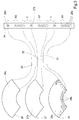
- FIG.3 A preferred embodiment of the two measuring light guides 29 and 30 and the Reference light guide 31 is shown in Fig.3.
- the inputs 26, 27 and 28 of the individual channels KS, KP and KR each have a cross-sectional shape 26a, 27a and 28a, the enveloping boundary of which is essentially one Mapping of the contour of the aperture 5b corresponds.
- FIG Channel KR of the reference light guide 31 is shown as an example.
- the quarter pupil shape of the aperture diaphragm is at the channel entrance 28 5 on the cross-sectional area of the ends of the bundle of optical fibers 28b shown.
- the output ends of the individual channels KS, KP and KR are each in terms of use a CCD detector as evaluation device 33 on the coupling device 34 spread out in a line.
- the arrangement of the individual optical fibers 26b to 28b are grouped in such a way that the optical fibers are continuous rising or falling angle of incidence on the sample P. This has the advantage that the intensity fluctuations among neighboring ones Optical fibers of a channel are lower than with a random arrangement fail, creating crosstalk effects between neighboring ones Optical fibers remain low.
- the grouping is done for all channels KS, KP and KR in the same way.
- optical fiber ends on the coupling device 34 also according to another arrangement regulation in a defined manner to be arranged to each other.
- they can be the same Angle of incidence belonging to optical fibers of different channels KS, KP and KR can be grouped together.
- the individual channels KS, KP and KR on the Evaluation device 33 has a separation distance T between each of them.
- the individual channels KS, KP and KR are separated by a distance T. separated from each other by, for example, 0.4 mm to 1 mm, the total length the channels lined up one behind the other is, for example, 6 mm.
- the illustrated embodiment uses an imaging mirror grating spectrograph used with a two-dimensional CCD detector. This CCD detector is sensitive in the wavelength range from 190 nm to 800 nm. By using a backlit, UV sensitive and cooled CCD detector with low dark current is a fast one Reading of the measurement spectra possible within one second.
- the mirror lens 15 shown in FIG. 6 has a 74-fold magnification with a numerical aperture of 0.65.
- the distance between the The converging lens 25 and the pinhole mirror 19 are 20 mm.
- the individual optical fibers have a core diameter of approximately 50 ⁇ m to 150 ⁇ m.
- Optical fibers with a core diameter of 80 ⁇ m are used, so that there are about ten optical fibers along the inner edge of the pupil surrender.
- FIG. 9 An alternative embodiment is shown in FIG. 9, around the high aperture the mirror lens 15 for a microspot at a measuring point M with a lateral resolution between 400 nm and 2 ⁇ m.
- the primary and secondary mirror of the mirror lens 15 in such a way set that this focuses in infinity.
- the polarizing one Beam splitter 22 is thus in an almost parallel light beam of the outgoing beam 18, which is advantageous for the beam path through the polarizing Beam splitter 22.
- a lens arrangement 35, 36, 37, 38 can be arranged, which is the reduction the beam width of the still parallel light beam that of the polarizing beam splitter 22 obtained s- and p-polarized output light beams 23, 24 is used.
- the measuring light guide 29 and 30 Around the output beams 23 and 24 of the polarizing Beam splitter 22 to one for the inputs 26 and 27 of the channels KS and KP the measuring light guide 29 and 30 to reduce the appropriate width between the polarizing beam splitter 22 and the inputs 26 and 27 one plano-convex lens 35 and 36 each and one plano-concave lens 37 or 38 similar to an inverted laser beam extension in a row arranged.
- a folding mirror 39 and a further lens optic 40 are provided.
Landscapes
- Physics & Mathematics (AREA)
- General Physics & Mathematics (AREA)
- General Health & Medical Sciences (AREA)
- Chemical & Material Sciences (AREA)
- Analytical Chemistry (AREA)
- Biochemistry (AREA)
- Life Sciences & Earth Sciences (AREA)
- Health & Medical Sciences (AREA)
- Immunology (AREA)
- Pathology (AREA)
- Investigating Or Analysing Materials By Optical Means (AREA)
- Length Measuring Devices By Optical Means (AREA)
- Lenses (AREA)
- Polarising Elements (AREA)
Abstract
Description
- Fig.1
- ein Ausführungsbeispiel einer optischen Meßanordnung zur Ellipsometrie, die hier zur Schichtdickenmessung eingesetzt wird,
- Fig.2
- eine Detailansicht einer Aperturblende, die in der Meßanordnung nach Fig.1 verwendet wird,
- Fig.3
- eine Detailansicht von in der Anordnung nach Fig.1 verwendeten Meß- und Referenzlichtleitern,
- Fig.4
- eine Durchblicköffnung einer Deuteriumlampe mit der Wendel einer Halogenlampe einer Beleuchtungseinrichtung der Anordnung nach Fig.1,
- Fig.5
- die Abbildung der Wendel der Halogenlampe in die Öffnung der Aperturblende,
- Fig.6
- eine schematische Darstellung eines Ausfallstrahles von einem Meßort an einer Probe bis zur Einkopplung in einen Meßlichtleiter, wobei hier ein in Fig.1 zusätzlich dargestellter polarisierender Strahlteiler weggelassen ist,
- Fig.7
- die Abbildung der Aperturöffnung auf einen runden Eingang eines Meßlichtleiterkanals,
- Fig.8
- eine Detailansicht der Anordnung eines Pinholespiegels in dem Ausfallstrahl zwischen dem Spiegelobjektiv und dem polarisierenden Strahlteiler, und in
- Fig.9
- eine Variante der Ausführungsform nach Fig.1, bei der der Ausfallstrahl als paralleles Lichtbündel in den polarisierenden Strahlteiler eingeleitet wird.
- 1
- Beleuchtungseinrichtung
- 2
- Halogenlampe
- 2a
- Wendel
- 3
- Deuteriumlampe
- 3a
- Durchblicköffnung
- 4
- Linsenanordnung
- 5
- Aperturblende
- 5a
- Metallfolie
- 5b
- Aperturöffnung
- 6
- Meßlichtstrahl
- 7
- Polarisator
- 8
- polarisierter Strahl
- 9
- nachgeschaltete Blende
- 10
- Feldblende
- 11
- Strahlteiler
- 12
- Referenzlichtstrahl
- 13
- Objektlichtstrahl
- 14
- Spiegel
- 15
- Spiegelobjektiv
- 15a
- Mittelspiegel
- 15b
- Stege
- 16
- Einfallstrahl
- 17
- Ausgangsstrahl
- 18
- Ausgangsstrahl
- 19
- Pinholespiegel
- 19a
- Pinhole
- 20
- Spiegelanordnung
- 21
- Videokamera
- 22
- polarisierender Strahlteiler
- 23,24
- Ausgangslichtstrahlen
- 25
- Sammellinse
- 26,27,28
- Eingang
- 26b,27b,28b
- Lichtleitfaser
- 29,30
- Meßlichtleiter
- 31
- Referenzlichtleiter
- 32
- Spektrograph
- 33
- Auswerteeinrichtung
- 34
- Koppeleinrichtung
- 35,36
- plankonvexe Linse
- 37,38
- plankonkave Linse
- T
- Trennabstand
- P
- Probe
- M
- Meßort
- KS,KP,KR
- Kanäle
Claims (10)
- Optische Meßanordnung mit einem Ellipsometer, bei dem ein Einfallstrahl (16) polarisierten Lichtes unter einem Einfallswinkel von α ≠ 0° auf einen Meßort (M) an der Oberfläche einer Probe (P) gerichtet ist und aus der Analyse eines von der Probe (P) reflektierten Ausfallstrahls (17) Informationen über Eigenschaften der Probe (P), bevorzugt über Schichtdicken sowie optische Materialeigenschaften, gewonnen werden, dadurch gekennzeichnet, daß der Einfallstrahl (16) durch ein Spiegelobjektiv (15) auf die Oberfläche der Probe (P) gerichtet ist und der Ausfallstrahl (17) ebenfalls durch das Spiegelobjektiv (15) erfaßt wird.
- Optische Meßanordnung nach Anspruch 1, dadurch gekennzeichnet, daß zur Einkopplung des von der Probe (P) reflektierten Lichtes in eine Auswerteeinrichtung (33) Meßlichtleiter (29, 30) vorgesehen sind, die eine Vielzahl von Lichtleitfasern umfassen, und daß ein Referenzlichtleiter (31) vorgesehen ist, über den der Auswerteeinrichtung (33) von der Probe (P) unbeeinflußtes Meßlicht zugeführt wird.
- Optische Meßanordnung nach Anspruch 1 oder 2, dadurch gekennzeichnet, daß dem Spiegelobjektiv (15) ein polarisierender Strahlteiler (22) nachgeschaltet ist, derart, daß der von dem Spiegelobjektiv (15) kommende Ausfallstrahl (18) nach Durchlaufen des Strahlteilers (22) in zwei s- und p-polarisierte Ausgangsstrahlen (23, 24) aufgespalten wird, die getrennt einer Auswerteeinrichtung (33) zugeführt werden.
- Optische Meßanordnung nach Anspruch 3, dadurch gekennzeichnet, daß zwischen dem polarisierenden Strahlteiler (22) und den zweikanalig ausgebildeten Meßlichtleitern (29, 30) eine Fokussierlinse (25) angeordnet ist, zur Fokussierung der aus dem polarisierenden Strahlteiler (22) erhaltenen s- und p-polarisierten Ausgangslichtstrahlen (23, 24) auf die jeweiligen Eingänge (26, 27) der Meßlichtleiter (29, 30).
- Optische Meßanordnung nach Anspruch 3, dadurch gekennzeichnet, daß das Spiegelobjektiv (15) auf unendlich fokussiert ist, derart daß der von dem Spiegelobjektiv (15) kommende Ausfallstrahl (18) als paralleles Strahlenbündel auf den zwischen dem Spiegelobjektiv (15) und der Auswerteeinrichtung (33) angeordneten, polarisierenden Strahlteiler (22) auftrifft.
- Optische Meßanordnung nach einem der Ansprüche 2 bis 5, dadurch gekennzeichnet, daß die einzelnen Lichtleitfasern (26b, 27b, 28b) der Meßlichtleiter (29, 30) und des Referenzlichtleiters (31) bis zu einer Kopplungseinrichtung (34) an einem Eingang der Auswerteeinrichtung (33) gebündelt geführt und an der Kopplungseinrichtung (34) aufgespreizt sind.
- Optische Meßordnung nach Anspruch 6, dadurch gekennzeichnet, daß die einzelnen Lichtleitfasern (26b, 27b, 28b) der Kanäle (KP, KS) der Meßlichtleiter (29, 30) für von der Probe (P) reflektiertes Licht und den Kanal (KR) des Referenzlichtleiters (31) für von der Probe (P) unbeeinflußtes Licht jeweils in linienartiger Anordnung aufgespreizt sind.
- Optische Meßanordnung nach Anspruch 6 oder 7, dadurch gekennzeichnet, daß für die Meßlichtleiter (29, 30) und den Referenzlichtleiter (31) die eingangsseitigen Enden und die ausgangsseitigen Enden der Lichtleitfasern (26b, 27b, 28b) in gleicher Lagebeziehung zueinander stehen.
- Optische Meßanordnung nach einem der Ansprüche 2 bis 8, dadurch gekennzeichnet, daß die eingangsseitigen Enden der Lichtleitfasern (26b, 27b, 28b) für jeden Kanal der Meßlichtleiter (29, 30) und des Referenzlichtleiters (31) über eine Fläche (26a, 27a, 28a) verteilt angeordnet sind, die der Form einer Öffnung (5b) einer Aperturblende (5) innerhalb eines von einer Beleuchtungsvorrichtung (1) abgestrahlten Meßlichtstrahls (6) nachgebildet ist, wobei die Aperturblende (5) vor einem Strahlteiler (11) zur Aufspaltung des Meßlichtstrahls (6) in einen von der Probe (P) zu beeinflussenden Anteil und einen von der Probe nicht zu beeinflussenden Anteil angeordnet ist.
- Optische Meßanordnung nach Anspruch 9, dadurch gekennzeichnet, daß die Beleuchtungsvorrichtung (1) eine Halogenlampe (2) und eine Deuteriumlampe (3) aufweist, wobei eine Wendel (2a) der Halogenlampe (2) durch eine Durchblicköffnung (3a) der Deuteriumlampe (3) hindurchscheint, und daß eine Linsenanordnung (4) vorgesehen ist, über welche die Wendel (2a) der Halogenlampe (2) in die Öffnung (5b) der Aperturblende (5) scharf abgebildet wird.
Applications Claiming Priority (2)
| Application Number | Priority Date | Filing Date | Title |
|---|---|---|---|
| DE10021378A DE10021378A1 (de) | 2000-05-02 | 2000-05-02 | Optische Messanordnung mit einem Ellipsometer |
| DE10021378 | 2000-05-02 |
Publications (3)
| Publication Number | Publication Date |
|---|---|
| EP1152236A2 true EP1152236A2 (de) | 2001-11-07 |
| EP1152236A3 EP1152236A3 (de) | 2002-04-03 |
| EP1152236B1 EP1152236B1 (de) | 2005-08-31 |
Family
ID=7640548
Family Applications (1)
| Application Number | Title | Priority Date | Filing Date |
|---|---|---|---|
| EP01109785A Expired - Lifetime EP1152236B1 (de) | 2000-05-02 | 2001-04-20 | Optische Messanordnung mit einem Ellipsometer |
Country Status (4)
| Country | Link |
|---|---|
| US (1) | US6600560B2 (de) |
| EP (1) | EP1152236B1 (de) |
| JP (1) | JP2002031510A (de) |
| DE (2) | DE10021378A1 (de) |
Families Citing this family (44)
| Publication number | Priority date | Publication date | Assignee | Title |
|---|---|---|---|---|
| US7230699B1 (en) | 2002-10-15 | 2007-06-12 | J.A. Woollam Co., Inc. | Sample orientation system and method |
| US7619752B2 (en) * | 2000-03-21 | 2009-11-17 | J. A. Woollam Co., Inc. | Sample orientation system and method |
| US7084978B1 (en) | 2003-04-03 | 2006-08-01 | J.A. Woollam Co., Inc. | Sample orientation system and method |
| US7333198B1 (en) | 2003-04-03 | 2008-02-19 | J.A. Woollam Co., Inc. | Sample orientation system and method |
| FR2810108B1 (fr) | 2000-06-09 | 2004-04-02 | France Telecom | Ellipsometre spectroscopique a faible bruit |
| US6862090B2 (en) * | 2001-08-09 | 2005-03-01 | Therma-Wave, Inc. | Coaxial illumination system |
| US7136162B1 (en) | 2002-10-15 | 2006-11-14 | J.A. Woollam Co., Inc. | Alignment of ellipsometer beam to sample surface |
| US8059276B2 (en) * | 2003-02-28 | 2011-11-15 | J.A. Woollam Co., Inc | Ellipsometric investigation and analysis of textured samples |
| US8570513B2 (en) | 2003-02-28 | 2013-10-29 | J.A. Woollam Co., Inc. | Ellipsometric investigation and analysis of textured samples |
| TWI235230B (en) * | 2003-12-03 | 2005-07-01 | Chung Shan Inst Of Science | Optical fixed-distance sensing apparatus |
| WO2005062986A2 (en) * | 2003-12-31 | 2005-07-14 | The University Of South Carolina | Thin-layer porous optical sensors for gases and other fluids |
| JP4474535B2 (ja) * | 2004-02-27 | 2010-06-09 | 株式会社テクノネットワーク四国 | 立体形状測定及び分析装置 |
| US20070201136A1 (en) * | 2004-09-13 | 2007-08-30 | University Of South Carolina | Thin Film Interference Filter and Bootstrap Method for Interference Filter Thin Film Deposition Process Control |
| US20070166245A1 (en) * | 2005-11-28 | 2007-07-19 | Leonard Mackles | Propellant free foamable toothpaste composition |
| WO2007064575A1 (en) * | 2005-11-28 | 2007-06-07 | Ometric Corporation | Optical analysis system and method for real time multivariate optical computing |
| EP1974201A1 (de) * | 2005-11-28 | 2008-10-01 | University of South Carolina | Optisches analysesystem zum dynamischen nachweis und messen in echtzeit |
| US8345234B2 (en) * | 2005-11-28 | 2013-01-01 | Halliburton Energy Services, Inc. | Self calibration methods for optical analysis system |
| US7623233B2 (en) | 2006-03-10 | 2009-11-24 | Ometric Corporation | Optical analysis systems and methods for dynamic, high-speed detection and real-time multivariate optical computing |
| US8027855B2 (en) * | 2006-05-30 | 2011-09-27 | Halliburton Energy Services Inc. | Methods of assessing and designing an application specific measurement system |
| WO2008002903A2 (en) | 2006-06-26 | 2008-01-03 | University Of South Carolina | Data validation and classification in optical analysis systems |
| EP2078187A2 (de) * | 2006-11-02 | 2009-07-15 | University of South Carolina | Optisches multianalyt-datenverarbeitungssystem |
| US8379199B2 (en) | 2006-11-02 | 2013-02-19 | Halliburton Energy Services, Inc. | Self-contained multivariate optical computing and analysis system |
| WO2008121692A1 (en) * | 2007-03-30 | 2008-10-09 | University Of South Carolina | Tablet analysis and measurement system |
| WO2008121684A1 (en) * | 2007-03-30 | 2008-10-09 | University Of South Carolina | Novel multi-analyte optical computing system |
| WO2008121715A1 (en) * | 2007-03-30 | 2008-10-09 | Ometric Corporation | In-line process measurement systems and methods |
| JP5172203B2 (ja) * | 2007-05-16 | 2013-03-27 | 大塚電子株式会社 | 光学特性測定装置および測定方法 |
| US8283633B2 (en) * | 2007-11-30 | 2012-10-09 | Halliburton Energy Services, Inc. | Tuning D* with modified thermal detectors |
| US8212213B2 (en) * | 2008-04-07 | 2012-07-03 | Halliburton Energy Services, Inc. | Chemically-selective detector and methods relating thereto |
| KR20100119332A (ko) | 2009-04-30 | 2010-11-09 | 삼성전자주식회사 | 광 집속 유니트 및 이를 갖는 스펙트럼 측정 장치 |
| US8248607B1 (en) * | 2009-08-04 | 2012-08-21 | J.A. Woollam Co., Inc. | Empirical correction for spectroscopic ellipsometric measurements of rough or textured surfaces |
| CN102062723B (zh) * | 2009-11-16 | 2013-01-16 | 中芯国际集成电路制造(上海)有限公司 | 检测铝连接线过热缺陷的方法 |
| DE102010041814B4 (de) | 2010-09-30 | 2020-07-23 | Carl Zeiss Ag | Ellipsometer |
| US9039907B2 (en) * | 2011-07-20 | 2015-05-26 | Imec | Methods for improving integrated photonic device uniformity |
| US9115987B2 (en) * | 2013-12-04 | 2015-08-25 | Nanometrics Incorporated | Optical metrology with multiple angles of incidence and/or azimuth angles |
| US10338362B1 (en) | 2014-06-06 | 2019-07-02 | J.A. Woollam Co., Inc. | Beam focusing and reflecting optics with enhanced detector system |
| US9921395B1 (en) | 2015-06-09 | 2018-03-20 | J.A. Woollam Co., Inc. | Beam focusing and beam collecting optics with wavelength dependent filter element adjustment of beam area |
| US9442016B2 (en) | 2014-06-06 | 2016-09-13 | J.A. Woollam Co., Inc | Reflective focusing optics |
| US10018815B1 (en) | 2014-06-06 | 2018-07-10 | J.A. Woolam Co., Inc. | Beam focusing and reflective optics |
| CN104316176B (zh) * | 2014-10-13 | 2016-12-07 | 中国电子科技集团公司第四十一研究所 | 一种紫外可见近红外双光源共光路及其输出方法 |
| KR101701798B1 (ko) * | 2015-02-09 | 2017-02-13 | 한양대학교 에리카산학협력단 | 입사각 분포를 최소화하는 집광형 타원해석기용 조리개 |
| DE102015103706A1 (de) | 2015-03-13 | 2016-09-15 | CiS Forschungsinstitut für Mikrosensorik GmbH | Optische Sensoranordnung zur Bestimmung der Eigenschaften einer dünnen Schicht |
| US11162897B2 (en) * | 2019-05-15 | 2021-11-02 | Onto Innovation Inc. | Optical metrology device using numerical aperture reduction |
| US11112231B2 (en) * | 2019-11-01 | 2021-09-07 | Applied Materials, Inc. | Integrated reflectometer or ellipsometer |
| JPWO2024122132A1 (de) * | 2022-12-06 | 2024-06-13 |
Family Cites Families (15)
| Publication number | Priority date | Publication date | Assignee | Title |
|---|---|---|---|---|
| JPH0224502A (ja) | 1988-07-12 | 1990-01-26 | Dainippon Screen Mfg Co Ltd | 膜厚測定方法 |
| NL8802920A (nl) * | 1988-11-28 | 1990-06-18 | Hoogovens Groep Bv | Laagdiktemeter. |
| US5042951A (en) * | 1989-09-19 | 1991-08-27 | Therma-Wave, Inc. | High resolution ellipsometric apparatus |
| WO1992012404A1 (en) * | 1991-01-11 | 1992-07-23 | Rudolph Research Corporation | Simultaneous multiple angle/multiple wavelength ellipsometer and method |
| US5412473A (en) | 1993-07-16 | 1995-05-02 | Therma-Wave, Inc. | Multiple angle spectroscopic analyzer utilizing interferometric and ellipsometric devices |
| US5608526A (en) * | 1995-01-19 | 1997-03-04 | Tencor Instruments | Focused beam spectroscopic ellipsometry method and system |
| JPH0933222A (ja) * | 1995-07-18 | 1997-02-07 | Dainippon Screen Mfg Co Ltd | 膜厚測定装置 |
| JPH09329670A (ja) * | 1996-06-11 | 1997-12-22 | Omron Corp | 物体検出装置 |
| US6198531B1 (en) * | 1997-07-11 | 2001-03-06 | University Of South Carolina | Optical computational system |
| US6134011A (en) * | 1997-09-22 | 2000-10-17 | Hdi Instrumentation | Optical measurement system using polarized light |
| US5917594A (en) * | 1998-04-08 | 1999-06-29 | Kla-Tencor Corporation | Spectroscopic measurement system using an off-axis spherical mirror and refractive elements |
| US6184984B1 (en) * | 1999-02-09 | 2001-02-06 | Kla-Tencor Corporation | System for measuring polarimetric spectrum and other properties of a sample |
| DE19953290A1 (de) * | 1999-11-05 | 2001-05-10 | Leica Microsystems | Verfahren und Vorrichtung zur Überwachung des von einer Beleuchtungsvorrichtung abgestrahlten Lichtes für ein optisches Messgerät |
| DE19963345A1 (de) * | 1999-12-27 | 2001-07-05 | Leica Microsystems | Optische Messanordnung und Verfahren zur Neigungsmessung |
| JP2004215114A (ja) * | 2003-01-07 | 2004-07-29 | Sony Corp | データ選択回路および電子機器 |
-
2000
- 2000-05-02 DE DE10021378A patent/DE10021378A1/de not_active Withdrawn
-
2001
- 2001-04-20 EP EP01109785A patent/EP1152236B1/de not_active Expired - Lifetime
- 2001-04-20 DE DE50107248T patent/DE50107248D1/de not_active Expired - Lifetime
- 2001-04-27 JP JP2001132337A patent/JP2002031510A/ja active Pending
- 2001-05-02 US US09/845,763 patent/US6600560B2/en not_active Expired - Lifetime
Also Published As
| Publication number | Publication date |
|---|---|
| US6600560B2 (en) | 2003-07-29 |
| JP2002031510A (ja) | 2002-01-31 |
| DE50107248D1 (de) | 2005-10-06 |
| EP1152236A3 (de) | 2002-04-03 |
| EP1152236B1 (de) | 2005-08-31 |
| DE10021378A1 (de) | 2001-11-08 |
| US20020027657A1 (en) | 2002-03-07 |
Similar Documents
| Publication | Publication Date | Title |
|---|---|---|
| EP1152236B1 (de) | Optische Messanordnung mit einem Ellipsometer | |
| DE4343076C2 (de) | Vorrichtung zum photothermischen Prüfen einer Oberfläche eines insbesondere bewegten Gegenstandes | |
| DE10004191B4 (de) | Fluoreszenz-Scanmikroskop | |
| DE102005043627B4 (de) | Optischer Sensor und Verfahren zur optischen Abstands- und/oder Farbmessung | |
| DE3232904C2 (de) | ||
| DE102013001238B4 (de) | Lichtmikroskop und Mikroskopieverfahren | |
| DE102009044151B4 (de) | Vorrichtung zur optischen Waferinspektion | |
| DE10392315B4 (de) | Optische Konfiguration und Verfahren für differentielle Brechungskoeffizientenmessungen | |
| EP3084399B1 (de) | Vorrichtung und verfahren zum untersuchen einer probe mittels optischer projektionstomografie | |
| DE10337040B4 (de) | Vorrichtung zur Untersuchung einer Oberfläche oder einer Schicht | |
| WO2010127872A1 (de) | Vorrichtung und verfahren zur winkelaufgelösten streulichtmessung | |
| EP1172642A2 (de) | Spektralellipsometer mit einer refraktiven Beleuchtungsoptik | |
| DE10042140A1 (de) | Beleuchtungs- und Abbildungseinrichtung für mehrere Spektralbereiche und Koordinatenmessmaschine mit einer Beleuchtungs- und Abbildungseinrichtung für mehrere Spektralbereiche | |
| EP2010862B1 (de) | Mikroskop und mikroskopierverfahren zur messung des oberflächenprofils eines objekts | |
| DE2758141C2 (de) | Spektrophotometer | |
| EP2276999B1 (de) | Optische anordnung zur beleuchtung eines messobjektes und interferometrische anordnung zur vermessung von flächen eines messobjektes | |
| DE10021379A1 (de) | Optische Messanordnung insbesondere zur Schichtdickenmessung | |
| DE102011087978A1 (de) | Verfahren und Anordnung zur Bestimmung des Brechzahlgradienten eines Materials | |
| EP3614130A1 (de) | Vorrichtung zur ermittlung optischer eigenschaften von proben | |
| DE4005878C2 (de) | ||
| EP3812697A1 (de) | Vorrichtung und verfahren zur profilmessung von flachen objekten mit unbekannten materialien | |
| DE10146945A1 (de) | Meßanordnung und Meßverfahren | |
| DE19748552C2 (de) | Auflichtmikroskop | |
| DE10231475A1 (de) | Scanmikroskop mit optischem Bauteil und optisches Bauteil | |
| DE102008047370A1 (de) | Partikelgrößenmessgerät |
Legal Events
| Date | Code | Title | Description |
|---|---|---|---|
| PUAI | Public reference made under article 153(3) epc to a published international application that has entered the european phase |
Free format text: ORIGINAL CODE: 0009012 |
|
| AK | Designated contracting states |
Kind code of ref document: A2 Designated state(s): DE FR GB Kind code of ref document: A2 Designated state(s): AT BE CH CY DE DK ES FI FR GB GR IE IT LI LU MC NL PT SE TR |
|
| AX | Request for extension of the european patent |
Free format text: AL;LT;LV;MK;RO;SI |
|
| PUAL | Search report despatched |
Free format text: ORIGINAL CODE: 0009013 |
|
| AK | Designated contracting states |
Kind code of ref document: A3 Designated state(s): AT BE CH CY DE DK ES FI FR GB GR IE IT LI LU MC NL PT SE TR |
|
| AX | Request for extension of the european patent |
Free format text: AL;LT;LV;MK;RO;SI |
|
| 17P | Request for examination filed |
Effective date: 20020925 |
|
| AKX | Designation fees paid |
Free format text: DE FR GB |
|
| GRAP | Despatch of communication of intention to grant a patent |
Free format text: ORIGINAL CODE: EPIDOSNIGR1 |
|
| GRAS | Grant fee paid |
Free format text: ORIGINAL CODE: EPIDOSNIGR3 |
|
| GRAA | (expected) grant |
Free format text: ORIGINAL CODE: 0009210 |
|
| AK | Designated contracting states |
Kind code of ref document: B1 Designated state(s): DE FR GB |
|
| PG25 | Lapsed in a contracting state [announced via postgrant information from national office to epo] |
Ref country code: GB Free format text: LAPSE BECAUSE OF FAILURE TO SUBMIT A TRANSLATION OF THE DESCRIPTION OR TO PAY THE FEE WITHIN THE PRESCRIBED TIME-LIMIT Effective date: 20050831 |
|
| REG | Reference to a national code |
Ref country code: GB Ref legal event code: FG4D Free format text: NOT ENGLISH |
|
| REF | Corresponds to: |
Ref document number: 50107248 Country of ref document: DE Date of ref document: 20051006 Kind code of ref document: P |
|
| GBV | Gb: ep patent (uk) treated as always having been void in accordance with gb section 77(7)/1977 [no translation filed] |
Effective date: 20050831 |
|
| PLBE | No opposition filed within time limit |
Free format text: ORIGINAL CODE: 0009261 |
|
| STAA | Information on the status of an ep patent application or granted ep patent |
Free format text: STATUS: NO OPPOSITION FILED WITHIN TIME LIMIT |
|
| 26N | No opposition filed |
Effective date: 20060601 |
|
| EN | Fr: translation not filed | ||
| PG25 | Lapsed in a contracting state [announced via postgrant information from national office to epo] |
Ref country code: FR Free format text: LAPSE BECAUSE OF FAILURE TO SUBMIT A TRANSLATION OF THE DESCRIPTION OR TO PAY THE FEE WITHIN THE PRESCRIBED TIME-LIMIT Effective date: 20061027 |
|
| PG25 | Lapsed in a contracting state [announced via postgrant information from national office to epo] |
Ref country code: FR Free format text: LAPSE BECAUSE OF FAILURE TO SUBMIT A TRANSLATION OF THE DESCRIPTION OR TO PAY THE FEE WITHIN THE PRESCRIBED TIME-LIMIT Effective date: 20050831 |
|
| PGFP | Annual fee paid to national office [announced via postgrant information from national office to epo] |
Ref country code: DE Payment date: 20170427 Year of fee payment: 17 |
|
| REG | Reference to a national code |
Ref country code: DE Ref legal event code: R119 Ref document number: 50107248 Country of ref document: DE |
|
| PG25 | Lapsed in a contracting state [announced via postgrant information from national office to epo] |
Ref country code: DE Free format text: LAPSE BECAUSE OF NON-PAYMENT OF DUE FEES Effective date: 20181101 |
|
| P01 | Opt-out of the competence of the unified patent court (upc) registered |
Effective date: 20230525 |