EP1152271A2 - Collier pour guide d'onde - Google Patents
Collier pour guide d'onde Download PDFInfo
- Publication number
- EP1152271A2 EP1152271A2 EP01110489A EP01110489A EP1152271A2 EP 1152271 A2 EP1152271 A2 EP 1152271A2 EP 01110489 A EP01110489 A EP 01110489A EP 01110489 A EP01110489 A EP 01110489A EP 1152271 A2 EP1152271 A2 EP 1152271A2
- Authority
- EP
- European Patent Office
- Prior art keywords
- clamping
- end piece
- clamp
- leg end
- optical fiber
- Prior art date
- Legal status (The legal status is an assumption and is not a legal conclusion. Google has not performed a legal analysis and makes no representation as to the accuracy of the status listed.)
- Withdrawn
Links
Images

Classifications
-
- F—MECHANICAL ENGINEERING; LIGHTING; HEATING; WEAPONS; BLASTING
- F16—ENGINEERING ELEMENTS AND UNITS; GENERAL MEASURES FOR PRODUCING AND MAINTAINING EFFECTIVE FUNCTIONING OF MACHINES OR INSTALLATIONS; THERMAL INSULATION IN GENERAL
- F16L—PIPES; JOINTS OR FITTINGS FOR PIPES; SUPPORTS FOR PIPES, CABLES OR PROTECTIVE TUBING; MEANS FOR THERMAL INSULATION IN GENERAL
- F16L33/00—Arrangements for connecting hoses to rigid members; Rigid hose-connectors, i.e. single members engaging both hoses
- F16L33/22—Arrangements for connecting hoses to rigid members; Rigid hose-connectors, i.e. single members engaging both hoses with means not mentioned in the preceding groups for gripping the hose between inner and outer parts
- F16L33/227—Arrangements for connecting hoses to rigid members; Rigid hose-connectors, i.e. single members engaging both hoses with means not mentioned in the preceding groups for gripping the hose between inner and outer parts the hose being introduced into or onto the connecting member and automatically locked
-
- G—PHYSICS
- G02—OPTICS
- G02B—OPTICAL ELEMENTS, SYSTEMS OR APPARATUS
- G02B6/00—Light guides; Structural details of arrangements comprising light guides and other optical elements, e.g. couplings
- G02B6/24—Coupling light guides
- G02B6/42—Coupling light guides with opto-electronic elements
- G02B6/4292—Coupling light guides with opto-electronic elements the light guide being disconnectable from the opto-electronic element, e.g. mutually self aligning arrangements
-
- H—ELECTRICITY
- H01—ELECTRIC ELEMENTS
- H01R—ELECTRICALLY-CONDUCTIVE CONNECTIONS; STRUCTURAL ASSOCIATIONS OF A PLURALITY OF MUTUALLY-INSULATED ELECTRICAL CONNECTING ELEMENTS; COUPLING DEVICES; CURRENT COLLECTORS
- H01R4/00—Electrically-conductive connections between two or more conductive members in direct contact, i.e. touching one another; Means for effecting or maintaining such contact; Electrically-conductive connections having two or more spaced connecting locations for conductors and using contact members penetrating insulation
- H01R4/28—Clamped connections, spring connections
- H01R4/48—Clamped connections, spring connections utilising a spring, clip, or other resilient member
- H01R4/4809—Clamped connections, spring connections utilising a spring, clip, or other resilient member using a leaf spring to bias the conductor toward the busbar
- H01R4/4811—Spring details
- H01R4/4816—Spring details the spring shape preventing insertion of the conductor end when the spring is unbiased
-
- H—ELECTRICITY
- H01—ELECTRIC ELEMENTS
- H01R—ELECTRICALLY-CONDUCTIVE CONNECTIONS; STRUCTURAL ASSOCIATIONS OF A PLURALITY OF MUTUALLY-INSULATED ELECTRICAL CONNECTING ELEMENTS; COUPLING DEVICES; CURRENT COLLECTORS
- H01R4/00—Electrically-conductive connections between two or more conductive members in direct contact, i.e. touching one another; Means for effecting or maintaining such contact; Electrically-conductive connections having two or more spaced connecting locations for conductors and using contact members penetrating insulation
- H01R4/28—Clamped connections, spring connections
- H01R4/48—Clamped connections, spring connections utilising a spring, clip, or other resilient member
- H01R4/4809—Clamped connections, spring connections utilising a spring, clip, or other resilient member using a leaf spring to bias the conductor toward the busbar
- H01R4/484—Spring housing details
- H01R4/4842—Spring housing details the spring housing being provided with a single opening for insertion of a spring-activating tool
-
- G—PHYSICS
- G02—OPTICS
- G02B—OPTICAL ELEMENTS, SYSTEMS OR APPARATUS
- G02B6/00—Light guides; Structural details of arrangements comprising light guides and other optical elements, e.g. couplings
- G02B6/24—Coupling light guides
- G02B6/36—Mechanical coupling means
- G02B6/3616—Holders, macro size fixtures for mechanically holding or positioning fibres, e.g. on an optical bench
Definitions
- the signal transmission surface Signal input surface or signal output surface
- an optoelectronic Converter usually a well modulatable Si diode as a receiver or as a transmitter
- terminals of this type for optical fibers e.g. known from DE 29 07 705 C2 and follow the basic structure of that Structure of the terminals for electrical copper conductors. That is obvious, because in the area of Data and signal transmission technology are the Lightwave further the technological successor the conventional copper conductor.
- a transmission technology Equivalent that is between one Glass fiber optic and a copper conductor with 1: 1000, i.e. with 1 kg of glass the same transmission performance can be achieved like with 1000 kg copper wire.
- This transmission technology Equivalent to one Optical fiber if this from relative lightweight plastic is made, even more unfavorable at the expense of conventional copper conductors.
- optical fibers are exactly the same to clamp like copper conductors. In both cases are used for the terminals a conductor entry channel used in which the conductor plugged in and by means of a the known designs of clamp springs clamped becomes. Compare the design a so-called cage tension spring according to FIG. 4 DE 27 60 179 C2 for a copper conductor with the same design as a cage tension spring 5 of DE 198 31 851 C1 for one Optical fiber.
- the object of the present invention is a clamp for connecting an optical fiber with the features of the generic term of claim 1 to develop so that in practice with the cage clamp connection technology in almost all cases a damping and Lossless optical fiber connection can be manufactured.
- clamping leg end piece executed in the manner of a cage clamp spring Clamping spring designed as a clamping and thrust element is in such a way that the from the Clamping leg end flap flap in itself and / or in its angle of attack ⁇ springy to the clamping leg end piece
- the clamp spring in the clamp housing with a pre-tension of the clamping leg end piece installed relative to the back of the clamping leg is such that the clamping leg end piece on a sliding curve of the terminal housing is present and that the glide curve the clamping leg end piece when opening or Closing the terminal controls such that the adjacent to the optical fiber Clamp a feed force on the Optical fiber in the direction of the cable entry exercises.
- the solution according to the invention ensures that even with a little careless and inaccurate positioning of the optical fiber in the conductor entry channel Clamp nevertheless an exact contact of the face of the optical fiber e.g. against the Signal transmission area of the signal port an optoelectronic converter automatically is enforced. Based on the following This is described in more detail in drawings.
- the feed force towards the optical fiber the leader also on one already clamped optical fiber during the total operating time of the terminal permanently is exercised because the clamping spring due to of their existing biases both in the clamping leg back (relative to that in the Terminal housing fixed spring root of the Clamping spring) as well as in the clamping leg end piece (relative to the back of the clamping leg) always yourself. So you can later thermal expansion of the material and / or occasionally increased Tensile forces on the optical fiber again be compensated for so that disturbances in the quality of the data and signal transmission be avoided.
- the bias of the clamping leg end piece relative to the back of the clamping leg the clamping spring in one or the other To choose direction.
- the sliding curve must be in the direction of the conductor entry the terminal housing end piece control so that when opening the clamping point against its bias is then moved when closing the Clamping point in the direction of the conductor entry to be able to move so that by means of the Clamp leg end piece issued and on the clamping tab attached to the optical fiber apply a feed force to the conductor to be able to.
- the core of the optical fiber consists of a Glass or plastic fiber and this reacts for the smallest scratches or notches or other damage to their surface condition with significantly deteriorated Damping values. That is why they are Core fibers of an optical fiber mostly with an additional protective cover underneath the outer jacket of the optical fiber protected. Care must be taken that neither the protective cover nor the outer jacket of the optical fiber by attaching the Cut through the clamping edge of the clamping and pushing element becomes. Nevertheless, a claw the clamping edge in the outer jacket otherwise there is a feed force on the optical fiber towards the conductor entry could not be raised.
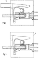
- Fig. 1 shows a simplified side view the terminal housing 5 of an optical fiber terminal, in which a commercially available optoelectronic Converter 6 is installed, one in his Signal port recessed signal transmission surface 7 owns.
- This signal transmission area stands above the floor space of the signal port and has to the outer circumference the signal port has a clear margin, to achieve that the fiber optic LWL 8 core fiber with a "dense" System contact on the signal transmission surface 7 may be concerned and not possibly by protruding material of the outer jacket of the LWL 8 is prevented.
- the FO 8 is (as shown in Fig. 1) in the conductor entry channel 9 of the terminal housing introduced and is in the 1 in an incorrect positioning such that its end End face 10 at a clear distance positioned to the signal transmission surface 7 is what's in practice at one in that Conductor entry channel 9 clamped Optical fiber must be avoided.
- Terminal point must be open. This is done in the usual and known way the blade of a screwdriver 12, the via an actuation opening in the terminal housing is inserted axially and thereby the upper back of the clamping leg of the clamping spring depressed, as shown in Fig. 1 is.
- the more precise details of the clamping spring 11 are shown in Fig. 4.
- the clamping leg end piece 15 with the clamping tab 17 is according to the teaching of the invention designed as a clamping and pushing element in the way that from the clamping leg end piece issued clamping tab in itself and / or in their angle of attack ⁇ to the clamping leg end piece (see Fig. 1) resilient Features, while still the Clamp spring in the clamp housing with a Preloading the clamping leg end piece 15 installed relative to the clamping leg back 14 is such that the clamping leg end piece on a sliding curve 18 of the terminal housing is present, as this is explained in more detail below is explained.
- the clamping spring shown in Fig. 4 has a clamping edge at the end of its clamping tab 19 for planting and clawing in the Outer jacket of the LWL 8. Adjacent to this The clamping tab 17 has a clamping edge contact surface protruding in the direction of the clamping edge 20, the depth of penetration of the clamping edge 19 limited in the outer jacket of the FO.
- the mode of operation of the clamping and pushing element (formed from the aforementioned clamping leg end piece 15 in combination with the special Properties of the clamping tab 17) opens up the reader from looking at the Sequence of functions according to FIGS. 1 to 3.
- FIG. 1 shows the fully open terminal point, recognizable by the fact that the blade of the Screwdriver 12 completely into the terminal housing has been inserted.
- opening the terminal point i.e. when depressing the Back of the clamping leg 14 slides the end of the clamping leg 15 on the sliding curve 18 along.
- the Clamp leg end piece 15 relative to the back of the clamp leg 14 a manufacturing technology Preload and is with this preload built into the terminal housing, so that Clamp leg end piece 15 always on the glide curve 18 is applied and controlled by this becomes.
- the control is such that the clamping leg end piece 15 of the clamping spring in Fig. 1st furthest to the left (as shown) is rebounded.
- FIG. 2 shows an intermediate stage of the functional sequence, in which the blade of the screwdriver 12 just as far out of the terminal housing withdrawn that the clamping edge 19th the clamping tab 17 for contact with the outer jacket of the LWL 8 has come and in the Outer jacket has clawed.
- the clamping tab 17 in their angle of attack ⁇ to the clamping leg end piece 15 slightly sprung.
- the Clamping leg end piece 15 lies on the sliding curve 18 in a region of the sliding curve, in which this begins, the clamping leg end piece 15 to the right as shown move.
Landscapes
- Engineering & Computer Science (AREA)
- General Engineering & Computer Science (AREA)
- Physics & Mathematics (AREA)
- Mechanical Engineering (AREA)
- General Physics & Mathematics (AREA)
- Optics & Photonics (AREA)
- Optical Couplings Of Light Guides (AREA)
- Mechanical Coupling Of Light Guides (AREA)
Applications Claiming Priority (2)
| Application Number | Priority Date | Filing Date | Title |
|---|---|---|---|
| DE10021882 | 2000-05-05 | ||
| DE10021882A DE10021882B4 (de) | 2000-05-05 | 2000-05-05 | LWL-Klemme |
Publications (2)
| Publication Number | Publication Date |
|---|---|
| EP1152271A2 true EP1152271A2 (fr) | 2001-11-07 |
| EP1152271A3 EP1152271A3 (fr) | 2003-06-04 |
Family
ID=7640874
Family Applications (1)
| Application Number | Title | Priority Date | Filing Date |
|---|---|---|---|
| EP01110489A Withdrawn EP1152271A3 (fr) | 2000-05-05 | 2001-04-27 | Collier pour guide d'onde |
Country Status (2)
| Country | Link |
|---|---|
| EP (1) | EP1152271A3 (fr) |
| DE (1) | DE10021882B4 (fr) |
Cited By (3)
| Publication number | Priority date | Publication date | Assignee | Title |
|---|---|---|---|---|
| CN100369327C (zh) * | 2002-11-16 | 2008-02-13 | 菲尼克斯电气公司 | 有彼此镜象对称的拉力弹簧的拉力弹簧夹 |
| EP2442403A1 (fr) * | 2010-10-12 | 2012-04-18 | Bals Elektrotechnik GmbH & Co. Kg | Borne de connexion sans vis |
| US12169316B2 (en) * | 2022-03-10 | 2024-12-17 | Kabushiki Kaisha Toshiba | Semiconductor device including leaf springs for holding optical fiber |
Families Citing this family (1)
| Publication number | Priority date | Publication date | Assignee | Title |
|---|---|---|---|---|
| DE102019122773B3 (de) * | 2019-08-26 | 2020-12-31 | Ifm Electronic Gmbh | Anschlussklemme für zwei Lichtleiter und deren Verwendung in einem Lichtleiterverstärker |
Family Cites Families (8)
| Publication number | Priority date | Publication date | Assignee | Title |
|---|---|---|---|---|
| BE507469A (fr) * | ||||
| DE2760179C2 (de) * | 1977-02-16 | 1985-12-05 | Wago-Kontakttechnik Gmbh, 4950 Minden | Schraubenlose Anschluß- und/oder Verbindungsklemme |
| DE2907705C2 (de) * | 1979-02-28 | 1984-10-11 | Schaltbau GmbH, 8000 München | Vorrichtung zum Andrücken eines Lichtwellenleiters an ein photoelektrisches Bauelement |
| DE3118057C2 (de) * | 1981-05-07 | 1984-07-05 | Karl Lumberg GmbH & Co, 5885 Schalksmühle | Anschlußklemme für elektrische Leiter |
| DE3911459A1 (de) * | 1989-04-05 | 1990-10-11 | Wago Verwaltungs Gmbh | Schraubenlose anschluss- und/oder verbindungsklemme |
| DE19529028B4 (de) * | 1995-07-28 | 2008-01-24 | Wago Verwaltungsgesellschaft Mbh | Elektrische Federkraftklemme |
| DE19626080B4 (de) * | 1996-06-28 | 2005-12-29 | The Whitaker Corp., Wilmington | Anordnung zur Befestigung eines Lichtwellenleiters |
| DE19831851C1 (de) * | 1998-07-16 | 2000-02-10 | Harting Kgaa | Einrichtung zum Anschluß von Lichtwellenleiterkabeln |
-
2000
- 2000-05-05 DE DE10021882A patent/DE10021882B4/de not_active Expired - Fee Related
-
2001
- 2001-04-27 EP EP01110489A patent/EP1152271A3/fr not_active Withdrawn
Cited By (4)
| Publication number | Priority date | Publication date | Assignee | Title |
|---|---|---|---|---|
| CN100369327C (zh) * | 2002-11-16 | 2008-02-13 | 菲尼克斯电气公司 | 有彼此镜象对称的拉力弹簧的拉力弹簧夹 |
| EP2442403A1 (fr) * | 2010-10-12 | 2012-04-18 | Bals Elektrotechnik GmbH & Co. Kg | Borne de connexion sans vis |
| US8328588B2 (en) | 2010-10-12 | 2012-12-11 | Bals Elektrotechnik Gmbh & Co. Kg | Screwless connection terminal |
| US12169316B2 (en) * | 2022-03-10 | 2024-12-17 | Kabushiki Kaisha Toshiba | Semiconductor device including leaf springs for holding optical fiber |
Also Published As
| Publication number | Publication date |
|---|---|
| EP1152271A3 (fr) | 2003-06-04 |
| DE10021882A1 (de) | 2001-11-08 |
| DE10021882B4 (de) | 2010-09-16 |
Similar Documents
| Publication | Publication Date | Title |
|---|---|---|
| DE3689113T2 (de) | Optischer Stecker. | |
| DE3886583T2 (de) | Faseroptischer Koppler. | |
| DE3786900T2 (de) | Optischer Verbinder und dessen Herstellungsverfahren. | |
| DE69228557T2 (de) | Schutzmhuellung fuer eine optische faser | |
| EP1775612A2 (fr) | Dispositif de connexion de câble optique | |
| EP3776751B1 (fr) | Ensemble de connecteurs pour câble de données | |
| DE3124546C2 (fr) | ||
| EP3516438B1 (fr) | Connecteur et procédé de verrouillage et de déverrouillage d'un connecteur | |
| DE3517388A1 (de) | Anschlussteil fuer ein faser-optisches kabel | |
| DE69116246T2 (de) | Zugentlasteter Stecker für optische Fasern | |
| DE3313835C2 (de) | Vorrichtung zum Verbinden von Lichtleitern mit einem Gehäuse | |
| EP1152271A2 (fr) | Collier pour guide d'onde | |
| DE19831851C1 (de) | Einrichtung zum Anschluß von Lichtwellenleiterkabeln | |
| EP1229364B1 (fr) | Boítier de support pour guide d'ondes optiques | |
| DE102012110371A1 (de) | Steckverbindervorrichtung | |
| EP1598685A1 (fr) | Dispositif pour un raccordement optique enfichable | |
| DE4406154C2 (de) | Aufnahme mit Knickschutz für einen Faserspleiß | |
| EP1493053A1 (fr) | Connecteur de fibres optiques comportant des saillies de sertissage | |
| DE19830148C1 (de) | Anschlußelement für ein Lichtwellenleiterkabel | |
| DE102019122773B3 (de) | Anschlussklemme für zwei Lichtleiter und deren Verwendung in einem Lichtleiterverstärker | |
| DE19851867C2 (de) | Vorrichtung zur lösbaren Verbindung von Lichtwellenleitern miteinander oder mit elektrooptischen Sende- und/oder Empfangseinrichtungen | |
| DE10203961C1 (de) | Koppelanordnung zum Ankoppeln eines optischen Steckers mit einem Steckerstift an ein Montageröhrchen | |
| DE102014105523A1 (de) | Steckverbindervorrichtung | |
| DE102006046181A1 (de) | Zugentlastungsvorrichtung für ein Glasfaserkabel | |
| DE19512110C2 (de) | Anschlußklemme für ein Lichtwellenleiterkabel |
Legal Events
| Date | Code | Title | Description |
|---|---|---|---|
| PUAI | Public reference made under article 153(3) epc to a published international application that has entered the european phase |
Free format text: ORIGINAL CODE: 0009012 |
|
| AK | Designated contracting states |
Kind code of ref document: A2 Designated state(s): AT BE CH CY DE DK ES FI FR GB GR IE IT LI LU MC NL PT SE TR |
|
| AX | Request for extension of the european patent |
Free format text: AL;LT;LV;MK;RO;SI |
|
| PUAL | Search report despatched |
Free format text: ORIGINAL CODE: 0009013 |
|
| AK | Designated contracting states |
Designated state(s): AT BE CH CY DE DK ES FI FR GB GR IE IT LI LU MC NL PT SE TR |
|
| AX | Request for extension of the european patent |
Extension state: AL LT LV MK RO SI |
|
| RIC1 | Information provided on ipc code assigned before grant |
Ipc: 7H 01R 4/48 B Ipc: 7G 02B 6/38 B Ipc: 7B 60M 1/24 B Ipc: 7F 16L 3/00 B Ipc: 7H 01R 4/28 B Ipc: 7G 02B 6/42 B Ipc: 7G 02B 6/36 A |
|
| AKX | Designation fees paid | ||
| REG | Reference to a national code |
Ref country code: DE Ref legal event code: 8566 |
|
| STAA | Information on the status of an ep patent application or granted ep patent |
Free format text: STATUS: THE APPLICATION IS DEEMED TO BE WITHDRAWN |
|
| 18D | Application deemed to be withdrawn |
Effective date: 20031205 |