EP1152500A1 - Adaptateur pour dispositif périphérique d'un ordinateur personnel - Google Patents
Adaptateur pour dispositif périphérique d'un ordinateur personnel Download PDFInfo
- Publication number
- EP1152500A1 EP1152500A1 EP01117181A EP01117181A EP1152500A1 EP 1152500 A1 EP1152500 A1 EP 1152500A1 EP 01117181 A EP01117181 A EP 01117181A EP 01117181 A EP01117181 A EP 01117181A EP 1152500 A1 EP1152500 A1 EP 1152500A1
- Authority
- EP
- European Patent Office
- Prior art keywords
- type
- compactflash
- housing
- compatible
- shutter
- Prior art date
- Legal status (The legal status is an assumption and is not a legal conclusion. Google has not performed a legal analysis and makes no representation as to the accuracy of the status listed.)
- Withdrawn
Links
- 230000002093 peripheral effect Effects 0.000 title description 3
- 230000001681 protective effect Effects 0.000 abstract description 2
- 230000009977 dual effect Effects 0.000 description 25
- 239000000463 material Substances 0.000 description 8
- 239000004417 polycarbonate Substances 0.000 description 7
- 230000006835 compression Effects 0.000 description 5
- 238000007906 compression Methods 0.000 description 5
- 239000004033 plastic Substances 0.000 description 4
- 238000000034 method Methods 0.000 description 3
- 229920001187 thermosetting polymer Polymers 0.000 description 3
- 239000000853 adhesive Substances 0.000 description 2
- 230000001070 adhesive effect Effects 0.000 description 2
- 229920005989 resin Polymers 0.000 description 2
- 239000011347 resin Substances 0.000 description 2
- 229920005992 thermoplastic resin Polymers 0.000 description 2
- 229920002799 BoPET Polymers 0.000 description 1
- 239000004593 Epoxy Substances 0.000 description 1
- 239000005041 Mylar™ Substances 0.000 description 1
- 239000004677 Nylon Substances 0.000 description 1
- NIXOWILDQLNWCW-UHFFFAOYSA-N acrylic acid group Chemical group C(C=C)(=O)O NIXOWILDQLNWCW-UHFFFAOYSA-N 0.000 description 1
- 230000001413 cellular effect Effects 0.000 description 1
- 238000006243 chemical reaction Methods 0.000 description 1
- 238000013497 data interchange Methods 0.000 description 1
- 238000002347 injection Methods 0.000 description 1
- 239000007924 injection Substances 0.000 description 1
- 230000015654 memory Effects 0.000 description 1
- 239000002184 metal Substances 0.000 description 1
- 239000002991 molded plastic Substances 0.000 description 1
- 229920001778 nylon Polymers 0.000 description 1
- 230000008520 organization Effects 0.000 description 1
- 229920000515 polycarbonate Polymers 0.000 description 1
- 229920001296 polysiloxane Polymers 0.000 description 1
- 239000012858 resilient material Substances 0.000 description 1
- 238000003466 welding Methods 0.000 description 1
Images


Classifications
-
- H—ELECTRICITY
- H01—ELECTRIC ELEMENTS
- H01R—ELECTRICALLY-CONDUCTIVE CONNECTIONS; STRUCTURAL ASSOCIATIONS OF A PLURALITY OF MUTUALLY-INSULATED ELECTRICAL CONNECTING ELEMENTS; COUPLING DEVICES; CURRENT COLLECTORS
- H01R31/00—Coupling parts supported only by co-operation with counterpart
- H01R31/06—Intermediate parts for linking two coupling parts, e.g. adapter
-
- H—ELECTRICITY
- H01—ELECTRIC ELEMENTS
- H01R—ELECTRICALLY-CONDUCTIVE CONNECTIONS; STRUCTURAL ASSOCIATIONS OF A PLURALITY OF MUTUALLY-INSULATED ELECTRICAL CONNECTING ELEMENTS; COUPLING DEVICES; CURRENT COLLECTORS
- H01R27/00—Coupling parts adapted for co-operation with two or more dissimilar counterparts
-
- H—ELECTRICITY
- H01—ELECTRIC ELEMENTS
- H01R—ELECTRICALLY-CONDUCTIVE CONNECTIONS; STRUCTURAL ASSOCIATIONS OF A PLURALITY OF MUTUALLY-INSULATED ELECTRICAL CONNECTING ELEMENTS; COUPLING DEVICES; CURRENT COLLECTORS
- H01R13/00—Details of coupling devices of the kinds covered by groups H01R12/70 or H01R24/00 - H01R33/00
- H01R13/44—Means for preventing access to live contacts
- H01R13/447—Shutter or cover plate
- H01R13/453—Shutter or cover plate opened by engagement of counterpart
- H01R13/4538—Covers sliding or withdrawing in the direction of engagement
-
- H—ELECTRICITY
- H01—ELECTRIC ELEMENTS
- H01R—ELECTRICALLY-CONDUCTIVE CONNECTIONS; STRUCTURAL ASSOCIATIONS OF A PLURALITY OF MUTUALLY-INSULATED ELECTRICAL CONNECTING ELEMENTS; COUPLING DEVICES; CURRENT COLLECTORS
- H01R2201/00—Connectors or connections adapted for particular applications
- H01R2201/06—Connectors or connections adapted for particular applications for computer periphery
Definitions
- the invention relates to adapters for connecting devices to personal computers.
- peripheral cards containing circuits and devices such as memories and modems.
- PCMCIA Personal Computer Memory Card International Association
- JEDIC Japan Electronic Data Interchange Council
- ISO International Organization for Standardization
- CFA Compact Flash Association
- U.S. Patent No. 5,490,891 discloses a housing for such a PC card, and a process for making same.
- the housing disclosed in the '891 Patent meets standards defined in the PCMCIA CompactFlash Specification Revision 2.1.1, incorporated herein by reference.
- Type I cards have an approximate length of 36 mm, an approximate width of 42 mm, and an approximate thickness of 3.3 mm.
- Type I cards were originally intended for use with products other than personal computers. Therefore, to connect a Type I card to a personal computer, an adaptor providing a PCMCIA interface at one end and an interface for the Type I card at the other end is used. These adapters will be referred to as Type I adapters. The Type I adapter plugs into the personal computer interface for PC Cards and the Type I card plugs into the Type I adapter.
- a card with this new format which will be referred to as a Type II card, has the same width and length as a Type I card but is thicker than the Type I card.
- Type II cards are as thick as PC Cards and Type 1 Adapters. Due to its thickness, the Type II card does not fit inside a standard PC Card housing or a Type I adapter. Consequently, the Type II card cannot be used with the Type I adapters currently used with Type I cards.
- the position of the Type II card socket holes and pins with respect to the bottom of the card is the same as that for the Type I card. Therefore, the Type II card's socket holes are offset from its center toward the bottom of the card on account of the Type II card's increased thickness.
- Type II cards have grooves, approximately 1.0-1.2 mm deep, 36.4 mm long, and 1.7 mm high, running along the two side walls that correspond to the grooves running along the side walls of the Type I card.
- the grooves on the Type II card are offset toward the bottom of the card.
- Type II cards Standards covering the Type II card have been proposed. These proposed standards require that Type II cards have a thickness of no more than 5 mm, and that the center line of the holes be approximately 1 mm above the bottom of the Type II card.
- the invention provides an adapter configured to connect both Type I and Type II cards into a PCMCIA compliant PC Card interface on a personal computer. More specifically, the invention provides a protective shutter mechanism adapted to receive both Type I and Type II cards.
- an apparatus for adapting a CompactFlash compatible electronic device to a PCMCIA compatible male connector comprises a PCMCIA compatible female connector, a CompactFlash compatible male connector, an electrical connection between the female connector and the male connector, and a housing supporting the male connector and the female connector.
- the housing has a top, a bottom, and a thickness between the top and the bottom that is essentially the maximum thickness that complies with the PCMCIA standard, and the male connector has pins arranged and the housing is configured to enable connection of either a type 1 or a type 2 CompactFlash electronic device to the male connector.
- the housing may include a bay which spans the full thickness of the housing and which spans enough of the width of the housing to accommodate the width of a CompactFlash-compatible electronic device.
- a CompactFlash Type I-compatible or Type-2 compatible electronic device may be held fully within the bay, the CompactFlash device having a female connector mated with the male connector.
- the apparatus may include a shutter movable relative to the housing from a first position in which the pins are exposed for connection to a female connector to a second position in which the pins are protected.
- the dual mode adapter can be used with both Type I and Type II cards.
- the dual mode adapter shutter protects the male connector pins from damage when they are not engaged.
- the shutter and its locking mechanism are an integrated unitary piece, and as such, the dual mode adapter contains few parts and is unlikely to break.
- the dual mode adapter is easily and economically manufactured.
- the dual mode adapter is inexpensive, yet provides sufficient structural integrity in an aesthetically pleasing package.
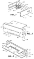
- a dual mode adapter 10 has two covers 101, 102. a frame 103 having a bay 104, a female connector 105, a header 106 having male connector pins 107, an electrical connection 108 between female connector 105 and header 106, a shutter 109, and two compression springs 110.
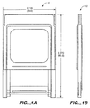
- dual mode adapter 10 When assembled, dual mode adapter 10 has a width and height conforming to PCMCIA standards set for PC Card devices. Namely, as assembled, the adapter has a length of approximately 85 mm, a width of approximately 54 mm, and is no more than approximately 5 mm thick.
- covers 101, 102 may be substantially rectangular in shape and may be stamped from metal or formed from plastic material.
- the covers 101, 102 serve to protect the internal components of dual mode adapter 10.
- Covers 101, 102 are connected to frame 103 along their longer sides.
- frame 103 includes two opposing side rails 117 to hold covers 101, 102 together.
- side rails 117 of frame 103 may be held together by a pair of ribs (not shown) that intersect side rails 117 at an angle.
- Frame 103 serves to hold covers 101, 102 together and support female connector 105, electrical connection 108, header 106, and shutter 109 between covers 101, 102.
- Side rails 117 of frame 103 form bay 104 in the front half of dual mode adapter 10.
- the dimensions of bay 104 are such that a Type I or Type II card conforming to CFA standards can slide into bay 104 and connect to header 106 through shutter 109.
- the frame 103, side rails 117 and ribs, if present, may be a unitary body formed from any suitable material.
- Female connector 105 conforms to PCMCIA standards and is located at the end of the assembled dual mode adapter opposite bay 104.
- the outer face 123 of female connector 105 is rectangular and has holes 118 complying with PCMCIA standards to attach the dual mode adapter to a personal computer.
- the top and bottom edges of the outer face of female connector 105 each have a flange 119. When assembled, the edges of covers 101, 102 meet flanges 119 to encase all of female connector 105 except holes 118 in the body of dual mode adapter 10. This protects users from the sharp edges of covers 101, 102.
- the inner face of female connector 105 is electrically coupled to header 106 by electrical connection 108. Electrical connection 108 may be formed by any suitable medium, such as a printed circuit board (illustrated) or cables (not shown).
- header 106 has a rectangular front face 201 and two side walls which extend perpendicularly from the edges of front face 201 toward bay 104.
- Male connector pins 107 (only a representative sample of pins is shown), which conform to PCMCIA standards, project from front face 201 toward the front end of dual mode adapter 10.
- the side walls 111 are parallel to and longer than the male connecting pins.
- the inner surface of each side wall 111 has a guide rail 112.
- a knob 113 may extrude from the outer surface of each side wall 111 to fit within a corresponding slot 120 in frame 103 (see Figure 1C).
- Header 106 also includes two header apertures 202 (only one is shown in this perspective view) that extend from front face 201 to the back face of header 106. One aperture is located between male connector pins 107 and each side wall 111. Once the dual mode adapter is assembled, header 106 is located in the mid-section of frame 103 with male connection pins 107 facing bay 104 and its back face attached to electrical connector 108. Header 106 may be a unitary piece made of plastic material.
- shutter 109 is generally rectangular in shape.
- a thin flange 303 runs along the top and bottom edges of a front surface 304 of the shutter.
- the shutter 109 includes two grooves 301 which run along the outer surface of each side 306 of shutter 109. Grooves 301 mate with header guide rails 112 to slidably connect shutter 109 to header 106 (see Figure 1C). In addition, two shutter apertures 302 are formed in a back face 305 of the shutter, and may extend through the shutter to the front face 304.
- two connector pins 116 are attached to shutter 109 and extend toward the back of the dual mode adapter.
- the connector pins 116 may be inserted into and frictionally secured in two shutter apertures 302.
- shutter 109 is slidably connected to header 106 so that connector pins 116 extend into header apertures 202.
- the header apertures 202 are wider than connecting pins 116 so that connecting pins 116 slidably engage header 106.
- the compression springs 110 which are held in place by connector pins 116, bias shutter 109 away from front face 201 of header 106.
- Shutter 109 also includes holes 121, corresponding in number and location with male connector pins 107, which extend through the shutter body from front face 304 to back face 305.
- holes 121 may be offset from the center of shutter 109.
- the center line of the bottom row of holes 121 may be approximately 1 mm above bottom surface 305.
- both Type I and Type II cards can be used with the dual mode adapter 10. This offset, however, may not be required for other embodiments.
- Holes 121 are spaced to coincide with male connector pins 107 when shutter 109 and header 106 are engaged.
- a relatively thin planar sheet 114 is connected to the top back edge of shutter 109.
- a lip 115 extends along a rim of planar sheet 114.
- Shutter 109, including holes 121, planar surface 114. flanges 303 and grooves 301. may be an integrated unitary piece formed from plastic material.
- compression springs 110 urge shutter 109 into its forwardmost position so that planar sheet 114 covers and protects male connector pins 107.
- shutter 109 is forced back so that planar sheet 114 slips between cover 101 and electrical connection 108 and male connector pins 107 extend through holes 121 to engage the card.
- compression springs 110 force shutter 109 forward over male connector pins 107.
- the lip 115 engages the bottom rear edge of header 106 to limit the forward motion of shutter 109 and lock the shutter in place (see Figure 1D).
- shutter 109 is in its forwardmost position, the tips of male connector pins 107 are protected by the body of shutter 109, and planar sheet 114 covers one side of the unengaged male connector pins 107.
- lip 115 may be located along the edge of planar sheet 114.
- the planar sheet may include two tabs 122 that project toward header 106. Each tap has a lip 115 along the edge of the tab.
- FIG. 4 illustrates an embodiment of the shutter that includes a shroud 401.
- the shroud 401 is connected to the lower edge of shutter 109 and is disposed in a generally parallel arrangement with planar sheet 114.
- Shroud 401 is very thin and may be formed of nylon, Mylar, standard or engineering grade thermal plastic material, thermoset material, or the like.
- springs 116 are compressed and shutter 109 and shroud 401 slide toward header 106 so that shroud 401 slips between cover 102 and electrical connection 108.
- the motion of shutter 109 stops when the rear face of shutter 109 contacts the front face of header 106.
- shroud 401 slides out to cover and protect the side of male connector pins 107 opposite planar sheet 114.
- Type II cards are thicker than Type I cards, either a Type I or Type II card can fit in the bay 104 formed by frame 103.
- both Type I and Type II cards will engage the offset male connector pins which extend through the offset holes in the shutter.
- dual mode adapter 10 is capable of connecting to either a Type I or Type II card and conforms to PCMCIA standards.
Landscapes
- Connector Housings Or Holding Contact Members (AREA)
- Coupling Device And Connection With Printed Circuit (AREA)
- Debugging And Monitoring (AREA)
- Bus Control (AREA)
- Automatic Analysis And Handling Materials Therefor (AREA)
Applications Claiming Priority (3)
| Application Number | Priority Date | Filing Date | Title |
|---|---|---|---|
| US21463 | 1998-02-10 | ||
| US09/021,463 US6102715A (en) | 1998-02-10 | 1998-02-10 | Personal computer peripheral device adapter |
| EP99300887A EP0936705A3 (fr) | 1998-02-10 | 1999-02-08 | Adapteur pour dispositif périphérique d'un ordinateur personnel |
Related Parent Applications (1)
| Application Number | Title | Priority Date | Filing Date |
|---|---|---|---|
| EP99300887A Division EP0936705A3 (fr) | 1998-02-10 | 1999-02-08 | Adapteur pour dispositif périphérique d'un ordinateur personnel |
Publications (1)
| Publication Number | Publication Date |
|---|---|
| EP1152500A1 true EP1152500A1 (fr) | 2001-11-07 |
Family
ID=21804384
Family Applications (2)
| Application Number | Title | Priority Date | Filing Date |
|---|---|---|---|
| EP01117181A Withdrawn EP1152500A1 (fr) | 1998-02-10 | 1999-02-08 | Adaptateur pour dispositif périphérique d'un ordinateur personnel |
| EP99300887A Withdrawn EP0936705A3 (fr) | 1998-02-10 | 1999-02-08 | Adapteur pour dispositif périphérique d'un ordinateur personnel |
Family Applications After (1)
| Application Number | Title | Priority Date | Filing Date |
|---|---|---|---|
| EP99300887A Withdrawn EP0936705A3 (fr) | 1998-02-10 | 1999-02-08 | Adapteur pour dispositif périphérique d'un ordinateur personnel |
Country Status (6)
| Country | Link |
|---|---|
| US (2) | US6102715A (fr) |
| EP (2) | EP1152500A1 (fr) |
| JP (1) | JP2000029583A (fr) |
| CN (1) | CN1161680C (fr) |
| CA (1) | CA2261418A1 (fr) |
| TW (1) | TW480780B (fr) |
Cited By (1)
| Publication number | Priority date | Publication date | Assignee | Title |
|---|---|---|---|---|
| EP1382982B1 (fr) * | 2002-07-05 | 2004-10-06 | Agilent Technologies, Inc. | Dispositif optique avec compensation de chaleur |
Families Citing this family (58)
| Publication number | Priority date | Publication date | Assignee | Title |
|---|---|---|---|---|
| JPH11144450A (ja) * | 1997-11-10 | 1999-05-28 | Fujitsu Takamisawa Component Ltd | メモリカード |
| US6751692B1 (en) * | 1999-07-28 | 2004-06-15 | Matsushita Electric Industrial Co., Ltd. | Adapter for memory device and connecting method using the same |
| WO2001035333A1 (fr) * | 1999-11-05 | 2001-05-17 | Yamaichi Electronics Co., Ltd. | Connecteur de carte |
| JP3396457B2 (ja) * | 2000-02-08 | 2003-04-14 | 山一電機株式会社 | カードコネクタ |
| CN100381979C (zh) * | 2000-04-11 | 2008-04-16 | 姚立和 | 多接口存储卡及其转换模块 |
| JP3530460B2 (ja) | 2000-04-27 | 2004-05-24 | 山一電機株式会社 | カードコネクタ |
| JP2001313128A (ja) | 2000-04-27 | 2001-11-09 | Yamaichi Electronics Co Ltd | カードコネクタ |
| US20020090859A1 (en) * | 2000-05-26 | 2002-07-11 | Richard Brayden | Vertically integrated card housing |
| US7493437B1 (en) | 2000-07-06 | 2009-02-17 | Mcm Portfolio Llc | Flashtoaster for reading several types of flash memory cards with or without a PC |
| US6859369B2 (en) * | 2000-07-06 | 2005-02-22 | Onspec Electronic Inc. | Smartuniversal flash media card adapters |
| US7295443B2 (en) * | 2000-07-06 | 2007-11-13 | Onspec Electronic, Inc. | Smartconnect universal flash media card adapters |
| US6438638B1 (en) | 2000-07-06 | 2002-08-20 | Onspec Electronic, Inc. | Flashtoaster for reading several types of flash-memory cards with or without a PC |
| US7252240B1 (en) * | 2000-07-06 | 2007-08-07 | Onspec Electronics, Inc. | Memory module which includes a form factor connector |
| US7278051B2 (en) | 2000-07-06 | 2007-10-02 | Onspec Electronic, Inc. | Field-operable, stand-alone apparatus for media recovery and regeneration |
| JP3825614B2 (ja) | 2000-08-08 | 2006-09-27 | 山一電機株式会社 | カードエッジコネクタ |
| TW483535U (en) * | 2000-12-01 | 2002-04-11 | Jess Link Products Co Ltd | Slot device capable of being inserted with various cards for handheld computer |
| JP4181307B2 (ja) | 2001-01-19 | 2008-11-12 | 山一電機株式会社 | カードコネクタ |
| JP2002237340A (ja) | 2001-02-09 | 2002-08-23 | Yamaichi Electronics Co Ltd | カードエッジコネクタ |
| JP3464461B2 (ja) * | 2001-03-07 | 2003-11-10 | 山一電機株式会社 | コンタクト端子、および、それを備えるカード用コネクタ |
| US6402558B1 (en) * | 2001-03-13 | 2002-06-11 | Ritek Corporation | Memory card adapter |
| JP2002352212A (ja) * | 2001-05-29 | 2002-12-06 | Murata Mfg Co Ltd | Cfカード |
| KR20030029768A (ko) * | 2001-10-10 | 2003-04-16 | 엘지전자 주식회사 | 컴퓨터의 확장 카드 설치구조 |
| JP2003110259A (ja) * | 2001-10-02 | 2003-04-11 | Canon Inc | コネクタ、電子機器及び情報処理装置 |
| US6908342B2 (en) * | 2001-10-02 | 2005-06-21 | Canon Kabushiki Kaisha | Connector, electronic equipment using the connector and information processing unit |
| JP3775338B2 (ja) * | 2001-11-15 | 2006-05-17 | 松下電工株式会社 | メモリカード用コネクタ装置及びその製造方法 |
| JP3981942B2 (ja) * | 2001-11-27 | 2007-09-26 | モレックス インコーポレーテッド | 電気コネクタ |
| US20040038388A1 (en) * | 2001-12-19 | 2004-02-26 | Affymetrix, Inc. | Manufacturing process for array plate assembly |
| JP4351826B2 (ja) * | 2002-01-23 | 2009-10-28 | アルプス電気株式会社 | カード用コネクタ装置 |
| TW553444U (en) * | 2002-09-09 | 2003-09-11 | Carry Computer Eng Co Ltd | Tray-type silicon card reader |
| JP4019965B2 (ja) * | 2003-02-10 | 2007-12-12 | ソニー株式会社 | Icカードのアダプタ装置 |
| US7094106B2 (en) * | 2003-03-10 | 2006-08-22 | Matsushita Electric Works, Ltd. | Adaptor for memory card |
| JP3885746B2 (ja) * | 2003-03-10 | 2007-02-28 | 松下電工株式会社 | メモリカード用アダプタ |
| JP4231321B2 (ja) * | 2003-04-08 | 2009-02-25 | ソフトバンクBb株式会社 | Pcカード |
| JP2005129468A (ja) * | 2003-10-27 | 2005-05-19 | Yamaichi Electronics Co Ltd | Icカード接続用アダプタ |
| JP4485173B2 (ja) * | 2003-11-19 | 2010-06-16 | モレックス インコーポレイテド | メモリーカード用アダプタ |
| JP4210224B2 (ja) * | 2004-01-23 | 2009-01-14 | 山一電機株式会社 | 電子機器用カードコネクタ及びそれに使用されるコンタクト |
| JP4039372B2 (ja) * | 2004-02-13 | 2008-01-30 | ソニー株式会社 | 接続カード装着装置 |
| US6890188B1 (en) * | 2004-02-27 | 2005-05-10 | Imation Corp. | Memory card compatible with device connector and host connector standards |
| US7513801B2 (en) * | 2004-04-28 | 2009-04-07 | C-One Technology Corporation | Apparatus with detachably connected memory-card type adapter |
| US6976858B1 (en) * | 2004-05-26 | 2005-12-20 | Ddk Ltd. | Electric connector |
| CN2766381Y (zh) * | 2004-12-18 | 2006-03-22 | 富士康(昆山)电脑接插件有限公司 | 电子卡连接器 |
| JP4231023B2 (ja) | 2005-04-01 | 2009-02-25 | 山一電機株式会社 | Icカード用コネクタ |
| JP4669384B2 (ja) | 2005-12-09 | 2011-04-13 | 山一電機株式会社 | Icカード誤挿入防止機構、および、それを備えるicカード用コネクタ |
| US7396254B2 (en) * | 2006-05-15 | 2008-07-08 | Deere & Company | Flexible electrical connector/housing assembly |
| US7140891B1 (en) * | 2006-06-02 | 2006-11-28 | Cheng Uei Precision Industry Co., Ltd. | Dustproof receptacle connector |
| US7341465B2 (en) * | 2006-07-05 | 2008-03-11 | Hon Hai Precision Ind. Co., Ltd. | Electrical card connector having an anti-mismating mechanism |
| TWM318228U (en) * | 2006-11-02 | 2007-09-01 | Datafab Sys Inc | Structure for protecting terminal of memory card adapter |
| US7338303B1 (en) * | 2006-12-06 | 2008-03-04 | Hon Hai Precision Ind. Co., Ltd. | Card connector assembly having carriage component |
| JP4607217B2 (ja) | 2008-07-23 | 2011-01-05 | 山一電機株式会社 | カードコネクタ |
| TWI384841B (zh) * | 2008-08-27 | 2013-02-01 | Asustek Comp Inc | 行動通訊裝置及其卡座 |
| JP5533028B2 (ja) | 2009-04-01 | 2014-06-25 | 山一電機株式会社 | Icカード用コネクタ |
| JP5013278B2 (ja) | 2009-08-04 | 2012-08-29 | 山一電機株式会社 | Icカード用コネクタ |
| US8501122B2 (en) | 2009-12-08 | 2013-08-06 | Affymetrix, Inc. | Manufacturing and processing polymer arrays |
| US8550858B2 (en) * | 2010-04-07 | 2013-10-08 | Apple Inc. | Extensible memory card-compatible receptacle and port expansion device |
| US8177564B1 (en) | 2010-12-03 | 2012-05-15 | Yamaichi Electronics Co., Ltd. | Receptacle connector and an electrical connector using the same |
| CN102219357A (zh) * | 2011-05-16 | 2011-10-19 | 四川嘉华企业(集团)股份有限公司 | 一种空心玻璃微珠的生产工艺及其设备 |
| JP5782064B2 (ja) * | 2013-04-15 | 2015-09-24 | 富士フイルム株式会社 | 内視鏡システム |
| WO2015141597A1 (fr) * | 2014-03-17 | 2015-09-24 | 株式会社リコー | Connecteur et appareil électronique comportant un connecteur |
Citations (4)
| Publication number | Priority date | Publication date | Assignee | Title |
|---|---|---|---|---|
| US4695925A (en) * | 1985-09-30 | 1987-09-22 | Mitsubishi Denki Kabushiki Kaisha | IC card |
| US5375037A (en) * | 1992-01-14 | 1994-12-20 | Gemplus Card International | Memory card having a recessed portion with contacts connected to an access card |
| US5600800A (en) * | 1992-06-29 | 1997-02-04 | Elonex I.P. Holdings, Ltd. | Personal computer system having a docking bay and a hand-held portable computer adapted to dock in the docking bay by a full-service parallel bus |
| US5608606A (en) * | 1994-06-14 | 1997-03-04 | Apple Computer, Inc. | Computer plug-in module and interconnection system for wireless applications |
Family Cites Families (31)
| Publication number | Priority date | Publication date | Assignee | Title |
|---|---|---|---|---|
| US3651444A (en) * | 1970-06-23 | 1972-03-21 | Amp Inc | Printed circuit board connector |
| US3747047A (en) * | 1971-12-01 | 1973-07-17 | Hughes Aircraft Co | Latchable integrally molded electrical connector |
| BE795208A (fr) * | 1972-02-11 | 1973-05-29 | Burndy Electra Spa | Connecteur propre a etablir automatiquement des connexions electriques entre des vehicules |
| US4445739A (en) * | 1982-05-04 | 1984-05-01 | Wooten Norman W | Male plug with automatic prong cover |
| DE3223494A1 (de) * | 1982-06-24 | 1983-12-29 | Multi-Contact AG Basel, 4056 Basel | Sicherheitseinrichtung an einem stecker |
| DE3610009A1 (de) * | 1986-03-25 | 1987-10-01 | Heinrich C Kosmeier | Elektrische steckeranordnung mit beruehrungsschutz |
| JPH07100088B2 (ja) * | 1986-11-07 | 1995-11-01 | 任天堂株式会社 | ゲ−ム機用カ−トリツジのアダプタ |
| US4775327A (en) | 1987-02-17 | 1988-10-04 | Amphenol Corporation | Connector with automatic protection cap |
| JP2534204B2 (ja) * | 1987-03-31 | 1996-09-11 | 三菱電機株式会社 | 半導体装置カ−ド |
| JPS63242692A (ja) * | 1987-03-31 | 1988-10-07 | 三菱電機株式会社 | 半導体装置カ−ド |
| JPH0775030B2 (ja) | 1987-08-07 | 1995-08-09 | 沖電気工業株式会社 | カード型集積回路のコネクタ |
| US4810199A (en) * | 1987-11-25 | 1989-03-07 | Kar Kishore K | Safety electrical plug |
| US4959609A (en) * | 1988-01-27 | 1990-09-25 | Manfred Prokopp | Electrical connecting apparatus for an electrical or electronic testing unit |
| KR930009394B1 (ko) * | 1988-02-12 | 1993-10-02 | 세이꼬 엡슨 가부시끼가이샤 | 커넥터의 전하를 제거하기 위한 구조체 |
| JPH0541509Y2 (fr) | 1988-03-03 | 1993-10-20 | ||
| IT1219951B (it) * | 1988-05-31 | 1990-05-24 | Giancarlo Sacerdoti | Dispositivo di sicurezza per la rilevazione della corrente di terra e spina elettrica di sicurezza dotata di tale dispositivo |
| JPH02222087A (ja) * | 1989-02-23 | 1990-09-04 | Toshiba Corp | 記録媒体接続装置 |
| US5030119A (en) * | 1989-09-27 | 1991-07-09 | Safe Care Products, Inc. | Safety plug |
| US5035635A (en) * | 1990-09-04 | 1991-07-30 | Tsai Shiang Shiun | Revolving safety socket |
| US5466164A (en) * | 1993-03-09 | 1995-11-14 | Sumitomo Wiring Systems, Ltd. | Connector having a protective hood |
| US5397857A (en) * | 1993-07-15 | 1995-03-14 | Dual Systems | PCMCIA standard memory card frame |
| US5472351A (en) * | 1993-10-06 | 1995-12-05 | U.S. Robotics, Inc. | Personal computer modem card interface construction |
| US5457606A (en) * | 1993-11-10 | 1995-10-10 | Raymond Engineering Inc. | Hermetically sealed PC card unit including a header secured to a connector |
| US5457601A (en) | 1993-12-08 | 1995-10-10 | At&T Corp. | Credit card-sized modem with modular DAA |
| US5889649A (en) | 1994-03-01 | 1999-03-30 | Canon Kabushiki Kaisha | Information processing apparatus and a card-shaped adapter for smaller and larger storage medium |
| US5518411A (en) * | 1994-06-01 | 1996-05-21 | Belleci; Sal J. | Electrical plug with retractable prong shield |
| JPH0878096A (ja) * | 1994-08-31 | 1996-03-22 | Hosiden Corp | 多極コネクタ |
| US5412550A (en) * | 1994-10-14 | 1995-05-02 | Hsieh; Kuang Nan | Night lamp having a safety device |
| US5599196A (en) * | 1995-05-01 | 1997-02-04 | Powell; Patti J. | Electrical plug safety cover |
| US5846092A (en) * | 1997-08-05 | 1998-12-08 | Minnesota Mining And Manufacturing Company | Plastic cased IC card adapter assembly |
| US6109940A (en) | 1998-10-09 | 2000-08-29 | Methode Electronics, Inc. | Shutter mechanism for card adapter |
-
1998
- 1998-02-10 US US09/021,463 patent/US6102715A/en not_active Expired - Fee Related
-
1999
- 1999-02-08 EP EP01117181A patent/EP1152500A1/fr not_active Withdrawn
- 1999-02-08 EP EP99300887A patent/EP0936705A3/fr not_active Withdrawn
- 1999-02-09 CA CA002261418A patent/CA2261418A1/fr not_active Abandoned
- 1999-02-10 JP JP11032988A patent/JP2000029583A/ja active Pending
- 1999-02-10 CN CNB991029925A patent/CN1161680C/zh not_active Expired - Fee Related
- 1999-03-19 TW TW088101987A patent/TW480780B/zh not_active IP Right Cessation
-
2000
- 2000-01-14 US US09/483,289 patent/US6413108B2/en not_active Expired - Fee Related
Patent Citations (4)
| Publication number | Priority date | Publication date | Assignee | Title |
|---|---|---|---|---|
| US4695925A (en) * | 1985-09-30 | 1987-09-22 | Mitsubishi Denki Kabushiki Kaisha | IC card |
| US5375037A (en) * | 1992-01-14 | 1994-12-20 | Gemplus Card International | Memory card having a recessed portion with contacts connected to an access card |
| US5600800A (en) * | 1992-06-29 | 1997-02-04 | Elonex I.P. Holdings, Ltd. | Personal computer system having a docking bay and a hand-held portable computer adapted to dock in the docking bay by a full-service parallel bus |
| US5608606A (en) * | 1994-06-14 | 1997-03-04 | Apple Computer, Inc. | Computer plug-in module and interconnection system for wireless applications |
Cited By (1)
| Publication number | Priority date | Publication date | Assignee | Title |
|---|---|---|---|---|
| EP1382982B1 (fr) * | 2002-07-05 | 2004-10-06 | Agilent Technologies, Inc. | Dispositif optique avec compensation de chaleur |
Also Published As
| Publication number | Publication date |
|---|---|
| EP0936705A2 (fr) | 1999-08-18 |
| US6413108B2 (en) | 2002-07-02 |
| CA2261418A1 (fr) | 1999-08-10 |
| CN1161680C (zh) | 2004-08-11 |
| CN1233004A (zh) | 1999-10-27 |
| JP2000029583A (ja) | 2000-01-28 |
| US20020001986A1 (en) | 2002-01-03 |
| US6102715A (en) | 2000-08-15 |
| EP0936705A3 (fr) | 2001-02-14 |
| TW480780B (en) | 2002-03-21 |
Similar Documents
| Publication | Publication Date | Title |
|---|---|---|
| US6102715A (en) | Personal computer peripheral device adapter | |
| CN1189985C (zh) | 卡片连接用适配器 | |
| US5846092A (en) | Plastic cased IC card adapter assembly | |
| JP3253918B2 (ja) | 標準プラグを受入れるための統合レセプタクルを備えた着脱可能i/oデバイス | |
| US5505628A (en) | Memory card frame and cover kit | |
| US7035110B1 (en) | Portable computer peripheral apparatus with reinforced connecting ring | |
| US8625270B2 (en) | USB flash drive with deploying and retracting functionalities using retractable cover/cap | |
| KR100433725B1 (ko) | 플래시 메모리 카드용 커넥터와 그것을 이용한 접속 구조및 이 접속 구조를 이용한 전자 장치 | |
| US5588850A (en) | Grounding means for memory card connector | |
| WO1999049540A1 (fr) | Carte pcmcia de type iii comportant des prises integrees servant a loger des fiches de communication normalisees | |
| US6139338A (en) | CF card adapter | |
| CN100546104C (zh) | 卡连接器和电子设备 | |
| EP1406204B1 (fr) | Support de carte pour un téléphone cellulaire | |
| US6430644B1 (en) | Electronic device having a configuration for connecting and removing an expansion module | |
| EP1510965A1 (fr) | Adaptateur pour carte | |
| JP2001147991A (ja) | ポータブルスマートカード読取装置 | |
| US6554627B1 (en) | Electronic card connector and method for assembling same | |
| US7488214B2 (en) | Memory card connector | |
| JP4454285B2 (ja) | 機能拡張カード | |
| US7288006B2 (en) | Electrical adapter | |
| CN201146291Y (zh) | 具有防误插功能的卡片连接器 | |
| JP4272939B2 (ja) | カード用コネクタ | |
| JPH07210646A (ja) | メモリカード | |
| JPH0981264A (ja) | カード状電子機器 |
Legal Events
| Date | Code | Title | Description |
|---|---|---|---|
| PUAI | Public reference made under article 153(3) epc to a published international application that has entered the european phase |
Free format text: ORIGINAL CODE: 0009012 |
|
| AC | Divisional application: reference to earlier application |
Ref document number: 936705 Country of ref document: EP |
|
| AK | Designated contracting states |
Kind code of ref document: A1 Designated state(s): AT BE CH CY DE DK ES FI FR GB GR IE IT LI LU MC NL PT SE |
|
| AX | Request for extension of the european patent |
Free format text: AL;LT;LV;MK;RO;SI |
|
| AKX | Designation fees paid | ||
| REG | Reference to a national code |
Ref country code: DE Ref legal event code: 8566 |
|
| STAA | Information on the status of an ep patent application or granted ep patent |
Free format text: STATUS: THE APPLICATION IS DEEMED TO BE WITHDRAWN |
|
| 18D | Application deemed to be withdrawn |
Effective date: 20020508 |