EP1152522A2 - Mécanisme d'entraínement électromécanique - Google Patents
Mécanisme d'entraínement électromécanique Download PDFInfo
- Publication number
- EP1152522A2 EP1152522A2 EP01108405A EP01108405A EP1152522A2 EP 1152522 A2 EP1152522 A2 EP 1152522A2 EP 01108405 A EP01108405 A EP 01108405A EP 01108405 A EP01108405 A EP 01108405A EP 1152522 A2 EP1152522 A2 EP 1152522A2
- Authority
- EP
- European Patent Office
- Prior art keywords
- actuators
- actuator
- transmitter body
- electromechanical actuator
- stroke
- Prior art date
- Legal status (The legal status is an assumption and is not a legal conclusion. Google has not performed a legal analysis and makes no representation as to the accuracy of the status listed.)
- Withdrawn
Links
Images



Classifications
-
- H—ELECTRICITY
- H02—GENERATION; CONVERSION OR DISTRIBUTION OF ELECTRIC POWER
- H02N—ELECTRIC MACHINES NOT OTHERWISE PROVIDED FOR
- H02N2/00—Electric machines in general using piezoelectric effect, electrostriction or magnetostriction
- H02N2/0005—Electric machines in general using piezoelectric effect, electrostriction or magnetostriction producing non-specific motion; Details common to machines covered by H02N2/02 - H02N2/16
- H02N2/001—Driving devices, e.g. vibrators
- H02N2/002—Driving devices, e.g. vibrators using only longitudinal or radial modes
- H02N2/0025—Driving devices, e.g. vibrators using only longitudinal or radial modes using combined longitudinal modes
-
- H—ELECTRICITY
- H02—GENERATION; CONVERSION OR DISTRIBUTION OF ELECTRIC POWER
- H02N—ELECTRIC MACHINES NOT OTHERWISE PROVIDED FOR
- H02N2/00—Electric machines in general using piezoelectric effect, electrostriction or magnetostriction
- H02N2/02—Electric machines in general using piezoelectric effect, electrostriction or magnetostriction producing linear motion, e.g. actuators; Linear positioners ; Linear motors
- H02N2/026—Electric machines in general using piezoelectric effect, electrostriction or magnetostriction producing linear motion, e.g. actuators; Linear positioners ; Linear motors by pressing one or more vibrators against the driven body
-
- H—ELECTRICITY
- H02—GENERATION; CONVERSION OR DISTRIBUTION OF ELECTRIC POWER
- H02N—ELECTRIC MACHINES NOT OTHERWISE PROVIDED FOR
- H02N2/00—Electric machines in general using piezoelectric effect, electrostriction or magnetostriction
- H02N2/10—Electric machines in general using piezoelectric effect, electrostriction or magnetostriction producing rotary motion, e.g. rotary motors
- H02N2/103—Electric machines in general using piezoelectric effect, electrostriction or magnetostriction producing rotary motion, e.g. rotary motors by pressing one or more vibrators against the rotor
Definitions
- the invention relates to an electromechanically drivable Actuator, motors using this actuator and a method for operating the actuator.
- DE 38 33 342 used in addition to a very high Repetition frequency of the movement in the ultrasound range (20-40 kHz) an amplitude transformation of the primary amplitude through the use of resonant actuators.
- the piezoceramic With the piezoceramic is so with a small movement amplitude at the node of Vibration excited a resonant vibration of a body which causes a typically by a factor at the antinode 50 increased movement amplitude is available.
- resonant operation has proven critical.
- High quality resonators are used so that the resonance becomes extremely narrow-band. This results in difficult insurmountable difficulties in the control when the Resonance frequency e.g. through temperature changes or changes of the load condition fluctuates.
- At least one electromechanical actuator has this a first electromechanical actuator and one of them spatially separated second electromechanical actuator.
- An electromechanical actuator has at least one electromechanical element.
- Under an electromechanical Element is understood to be a body in which a volume by applying an electrical signal (current, voltage etc.) is stretched, which results in a stroke of the actuator.
- electromechanical elements are electrostrictive Elements, magnetostrictive elements (e.g. including one electrical winding) or piezoelectric elements. These elements have in common that they can be controlled very precisely are and can apply high pressure forces. On the other hand is less than the component length Hub dl common that limits their direct application.
- the transmitter body On the actuators sits on.
- An expansion of the actuators in the direction the transmitter body is controllable, e.g. B. by creating one electrical voltage.
- the stroke dl of the actuators can transformed by using the transmitter body, i.e. in usually greatly enlarged.
- the transmitter body acts as a non-resonant operated biactive lever.
- An output body is in the presence of a friction contact carried along with the transmitter body.
- the control of the stretch is not restricted, so it can separately or coupled.
- the actuators can be controlled electronically.
- the transmitter body is preferably stiff.
- the actuators follow a magnetostrictive, an electrostrictive or in particular one Piezoelectric principle can be driven.
- the transmitter body is by means of a spring element is pressed onto the actuators, because at the same time the transmitter body fits well on the actuators and a pressure preload of the actuators can be achieved. At the same time, effects are more thermal Expansion can be compensated.
- the transmitter body is wedge-shaped Has cross-sectional area, with a bottom surface sits on the actuators because such an easy one controllable and versatile actuator results.
- the Transmitter element can e.g. be a spherical disc with seat.
- the motor has an output body has, which is transmitted by means of the friction contact Movement of the transmitter body is rotatable, for. Legs Wave.
- the engine has an output body has, which by means of the friction contact transmitted movement of the transmitter body is linearly displaceable is, e.g. a piston or sheet.
- the output body can both by the at least one actuator be rotatable and linearly displaceable.
- a stroke dl 2 of the first actuator and a stroke dl 3 of the second actuator are each changed periodically, so that a regular drive results.
- others e.g. B. non-periodic movements possible.
- ⁇ corresponds to an angular frequency and ⁇ a phase angle.
- a stroke can be adjusted by an analog setting of the drive voltage applied to the piezo elements, because the drive voltage and the stroke have a linear approximation to one another.
- Robotic arms Compact design light, fast, relatively long runtime, free of play
- Positioning e.g. B. in placement machines
- Compact design light, fast, relatively long runtime, free of play
- Valve adjustment fast freedom of play
- Figure 1 shows a sectional side view of the (x, y) plane a motor that uses an electromechanical Actuator can be excited to a rotary movement.
- the actuator consists of a transmitter body 1, a first piezomechanical actuator 2, a second piezomechanical actuator 3, a spring element 4, and two transmitter elements 6, 7.
- An output body 5 of the motor is driven by the actuator.
- the output body 5 is here in the form of a rotor R, z. B. a shaft, which is excited to rotate by being carried along with the transmitter body 1.
- the electromechanical element of the actuators 2, 3 is in each case a multilayer piezo actuator using low-voltage technology, the stroke d1 of which acts in the direction of its longitudinal axis using the known d 33 longitudinal effect.
- the transmitter body 1 lies over the first transmitter element 6 on the first actuator 2 and over the second Transmitter element 7 on the second actuator 3.
- Means the tension of the spring element 4 becomes the transmitter body 1 pulled against the two actuators 2, 3 in such a way that the pressure in the middle of the working line of the two actuators 2.3 lies.
- this ensures a secure fit of the transmitter body 1 on the actuators 2, 3 guaranteed and on the other hand is a compressive bias of the piezomechanical Actuators 2.3 given.
- the transmitter body 1 is stiff. With its hardened He can drive tip S in the area of a contact point Pk be brought into frictional contact with the rotor R.
- the piezomechanical actuators 2, 3 are aligned so that their (positive and / or negative) stroke acts parallel to the y-axis in the direction of the transmitter body 1.
- the actuators 2, 3 also comprise a head plate and a foot plate.
- a similar control to elongate both actuators 2, 3 causes the transmitter tip S to engage the output body R, a similar control of the actuators 2,3 for contraction causes the friction contact to open.
- An uneven control of both actuators 2,3 e.g. elongation of the first actuator 2 and contraction of the second actuator 3 causes a movement of the Drive tip S of the transmitter body 1 in the direction of the contracted Actuators 2, 3 (e.g. the second actuator 3).
- FIG. 2 shows a possible movement curve of the contact tip S in the (x, y) plane as a function of a phase angle ⁇ .
- a different stroke or maximum stroke dl 0 of the individual actuators 2, 3 can also be advantageous for some applications.
- a movement according to Eq. [1] is in accordance with a piezoelectrically driven actuator analogous to a periodic control voltage U 2 or U 3 on the first actuator 2 or on the second actuator 3 with the same frequency
- U 2 U 0 Sin ( ⁇ t)
- U 3rd U 0 Sin ( ⁇ t + ⁇ ).
- the given deviation of the circular shape is due to the geometry of the transmitter body 1 adjustable.
- a phase angle ⁇ 180 ° or -180 ° corresponds to a maximum speed or translation speed of the motor.
- the size of the movement of the drive tip S in the x direction (“x-stroke") is directly through a choice of the geometry of the transmitter body 1 adjustable, especially by the ratio from height to width. This makes it possible for the x-stroke of the transmitter body 1 is many times larger than the maximum stroke dl of the actuators 2.3. This corresponds to one Stroke ratio with change in the direction of movement.
- the Actuators 2, 3 are usually advantageous only slightly bent, especially when the transmitter elements 6.7 are freely movable.
- Control voltages other than sinusoidal are also possible. It is also used, for example, to implement a three-dimensional one Movement curve possible, a transmitter body 1.1 ', 1' 'with more than two actuators 2.3 or Tilt actuators 2.3 against each other.
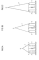
- Figures 3a to 3c each show an actuator 1,1 ', 1 "analogous to Figure 1, in which now the lengths of the oblique Sides of the transmitter body 1.1 '', 1 '' are designed differently are.
- FIG. 3b shows an actuator 1, which is the actuator 1 from Figure 1 corresponds.
- Figure 3a shows an actuator that one Transmitter body 1 'with shortened oblique sides for change of the ratio of height to width.
- the drive tip is S ' wider than in Figure 3b.
- Figure 3c shows an actuator that has a transmitter body 1 '' with extended sloping sides. This gives a reduced compared to the actuator in Figure 3b Power transmission at high speed.
- a shape of the transmitter body 1,1', 1 '' becomes.
- a transmitter body 1, 1 ', 1' ' can be used with different drive tips S, S ', S ", as a comparison between Figure 3a and 3b shows.
- a transmitter body 1,1 ', 1' 'with different Shape of the cross-sectional area e.g. B. angular, round, chamfered or can also be used in any shape.
- Figure 4 shows a sectional side view of a rotary motor analogous to Figure 1, in which the rotor R in Form of a shaft rotatably mounted about its longitudinal axis I. is.
- Figure 5 shows a side view of a linear motor in which a linear movement by means of the electromechanical actuator in the x direction (symbolized by the arrow) one general boom G, which is passed through two bearings L, is feasible.
- the linkage G can be a shaft, for example be or a flat ribbon. It is also possible to attach to an output body (5, R, S) to attack several actuators, for example to increase the torque or simultaneous rotary and linear movement.
- Figure 6 shows an oblique view of an embodiment of an engine for the realization of slowly rotating and heavily loaded Drives.
- the two actuators 2, 3 act as described above the rotation of the output body R, which is in the form of a Roller is present.
- An additional actuator 8 is used for locking during the frictional contact open at the front end used.
- Figure 7 shows a sectional side view of the (x, y) plane another embodiment of a motor, at an output body 5 in the form of a shaft by means of a electromechanical actuator can be excited to rotate is.
- the shaft 5 is now for reasons of space saving between the actuators 2.3 through it.
- the transmitter body 1 * is replaced by an under Compressed spring element 4 held on the transmitter elements 6.7 pressed.
Landscapes
- General Electrical Machinery Utilizing Piezoelectricity, Electrostriction Or Magnetostriction (AREA)
Applications Claiming Priority (2)
| Application Number | Priority Date | Filing Date | Title |
|---|---|---|---|
| DE10021863A DE10021863A1 (de) | 2000-05-05 | 2000-05-05 | Elektromechanischer Stellantrieb |
| DE10021863 | 2000-05-05 |
Publications (1)
| Publication Number | Publication Date |
|---|---|
| EP1152522A2 true EP1152522A2 (fr) | 2001-11-07 |
Family
ID=7640860
Family Applications (1)
| Application Number | Title | Priority Date | Filing Date |
|---|---|---|---|
| EP01108405A Withdrawn EP1152522A2 (fr) | 2000-05-05 | 2001-04-03 | Mécanisme d'entraínement électromécanique |
Country Status (2)
| Country | Link |
|---|---|
| EP (1) | EP1152522A2 (fr) |
| DE (1) | DE10021863A1 (fr) |
Cited By (1)
| Publication number | Priority date | Publication date | Assignee | Title |
|---|---|---|---|---|
| WO2008135463A1 (fr) * | 2007-05-07 | 2008-11-13 | Robert Bosch Gmbh | Dispositif d'actionnement piézoélectrique |
Families Citing this family (2)
| Publication number | Priority date | Publication date | Assignee | Title |
|---|---|---|---|---|
| DE10227509A1 (de) * | 2002-04-22 | 2003-11-06 | Elliptec Resonant Actuator Ag | Piezomotor |
| US9963046B2 (en) | 2009-07-15 | 2018-05-08 | Adient Luxembourg Holding S.a.r.l. | Mechatronic unlocking means |
Family Cites Families (2)
| Publication number | Priority date | Publication date | Assignee | Title |
|---|---|---|---|---|
| JPH06303782A (ja) * | 1993-04-14 | 1994-10-28 | Hitachi Ltd | 駆動装置 |
| DE4445642A1 (de) * | 1994-12-21 | 1996-06-27 | Marco Systemanalyse Entw | Piezoaktuatorisches Antriebs- bzw. Verstellelement |
-
2000
- 2000-05-05 DE DE10021863A patent/DE10021863A1/de not_active Withdrawn
-
2001
- 2001-04-03 EP EP01108405A patent/EP1152522A2/fr not_active Withdrawn
Cited By (2)
| Publication number | Priority date | Publication date | Assignee | Title |
|---|---|---|---|---|
| WO2008135463A1 (fr) * | 2007-05-07 | 2008-11-13 | Robert Bosch Gmbh | Dispositif d'actionnement piézoélectrique |
| WO2008135457A1 (fr) * | 2007-05-07 | 2008-11-13 | Robert Bosch Gmbh | Dispositif d'actionnement piézoélectrique |
Also Published As
| Publication number | Publication date |
|---|---|
| DE10021863A1 (de) | 2001-11-15 |
Similar Documents
| Publication | Publication Date | Title |
|---|---|---|
| EP0799502B1 (fr) | Element d'entrainement ou de reglage a actionnement piezo-electrique | |
| EP1098429B1 (fr) | Moteur électromécanique | |
| DE102016104803B4 (de) | Piezoelektrischer Schreitantrieb | |
| DE4435996C2 (de) | Drehantrieb | |
| DE102007023200B4 (de) | Elektromechanischer Motor, insbesondere piezoelektrischer Mikroschrittantrieb | |
| DE69709739T2 (de) | Piezoelektrischer motor mit unabhängigen statormodulen | |
| EP0505386B1 (fr) | Moteur pas a pas pour l'entrainement d'un corps, en particulier d'un arbre, par petits angles de rotation par pas | |
| DE102007023217B4 (de) | Elektromechanischer Motor, insbesondere piezoelektrischer Mikroschrittantrieb | |
| DE19909913B4 (de) | Elektromechanische Antriebsvorrichtung | |
| EP3490134B1 (fr) | Entraînement par inertie précontraint et procédé correspondant | |
| EP2064754A1 (fr) | Entrainement electromagnetique de reglage | |
| EP1152522A2 (fr) | Mécanisme d'entraínement électromécanique | |
| DE102012104749B4 (de) | Mehrachsige Aktorvorrichtung | |
| EP2158622B1 (fr) | Moteur électromécanique, notamment moteur pas à pas piézoélectrique | |
| DE19710601C2 (de) | Bewegungsgenerator | |
| EP1984961B8 (fr) | Dispositif d'entrainement inertiel rotatif | |
| EP3301730A1 (fr) | Convertisseur d'énergie | |
| DE102008021904A1 (de) | Rotationsantrieb | |
| EP1554795B1 (fr) | Moteur pas-a-pas lineaire | |
| EP2027613B1 (fr) | Dispositif d'entraînement d'actionneur de corps à l'etat solide ou procédé pour entraîner un dispositif d'entraînement d'actionneur de corps à l'etat solide | |
| DE102008001405A1 (de) | Piezoelektrische Antriebsvorrichtung, sowie Verfahren zum Betreiben einer solchen | |
| EP2112759A2 (fr) | Moteur piézoélectrique | |
| DE102020135154A1 (de) | Vorrichtung für ein Kraftfahrzeug | |
| WO2026002717A1 (fr) | Dispositif de réglage, utilisation d'un tel dispositif de réglage pour positionner des objets et procédé de positionnement d'objets en utilisant un tel dispositif de réglage | |
| EP1798182A2 (fr) | Système d'alignement de feuilles par tapotement |
Legal Events
| Date | Code | Title | Description |
|---|---|---|---|
| PUAI | Public reference made under article 153(3) epc to a published international application that has entered the european phase |
Free format text: ORIGINAL CODE: 0009012 |
|
| AK | Designated contracting states |
Kind code of ref document: A2 Designated state(s): AT BE CH CY DE DK ES FI FR GB GR IE IT LI LU MC NL PT SE TR |
|
| AX | Request for extension of the european patent |
Free format text: AL;LT;LV;MK;RO;SI |
|
| STAA | Information on the status of an ep patent application or granted ep patent |
Free format text: STATUS: THE APPLICATION HAS BEEN WITHDRAWN |
|
| 18W | Application withdrawn |
Withdrawal date: 20011211 |